Circor SR-3300 Einbau- Und Betriebsanleitung

Verwandte Anleitungen für Circor SR-3300

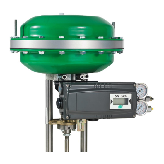
Inhaltszusammenfassung für Circor SR-3300
- Seite 1 Einbau- und Betriebsanleitung SR3300-8010 Installation and Operating instructions SR-3300 Page 1 07/2018...
-
Seite 2: Inhaltsverzeichnis
Produktbeschreibung………………………………………………………………………………….. Allgemeines…………………………………………………………………………………….…. Hauptmerkmale und Funktionen..................... Typenschildbeschreibung……………………………………………………………………….. Produktspezifikation……………………………………………………………………………. Einzelteile und Baugruppen …………..………………………………………………………..Produktabmessungen…………………………………………………………………………..…. Installation…………………………………………………………………………………………… 3.1 Sicherheit……………………………………………………………………………………….… 3.2 Installation des SR-3300……………………………………………………………… . Anschlüsse………………………………………………………………………………………… 4.1 Sicherheit………………………………………………………………………………… ……… 4.2 Versorgungsdruck-Bedingungen ..................4.3 Leitungssystem-Bedingungen…………………………………………………….……………. 4.4 Anschluss - Antrieb ......................4.4.1 Einfachwirkender Antrieb - SR-3300 .............. - Seite 3 Einbau- und Betriebsanleitung SR3300-8010 Installation and Operating instructions SR-3300 6.3.3.2 P-Wert (KP) ................6.3.3.3 D-Wert (Kd) .................. 6.3.3.4 I-Wert (KI) ..................6.3.3.5 P_(KP_), D_(Kd_), I_(KI_)-Werte ..........6.3.4 Handkalibrierungs-Modus (HAND CAL) ........... 6.3.4.1 Nullpunkt (PV_ZERO) und Endpunkt (PV_END) für Ventile ..
-
Seite 4: Einführung
Produktbeschreibung Allgemeines Der intelligente Stellungsregler der Serie SR-3300 dient der präzisen Steuerung des Ventilhubs als Reaktion auf ein von der Steuervorrichtung ausgesendetes Eingangssignal von 4 bis 20 mA. Der eingebaute Mikroprozessor optimiert die Leistung des Stellungsreglers und bietet weitere Funktionen wie Auto-Kalibrierung, PID-Regelung. -
Seite 5: Typenschildbeschreibung
Einbau- und Betriebsanleitung SR3300-8010 Installation and Operating instructions SR-3300 ➢ Hand – Automatik-Betrieb umschaltbar Typenschildbeschreibung SR-3300 Typenschild am Gerätegehäuse Model Number: Zeigt die Modellnummer des Stellungsreglers. Explosion Proof: Bezeichnet den zertifizierten Explosionsschutzgrad Input Signal: Bezeichnet den Eingangssignalbereich. Ambient Temp:. Bezeichnet die zulässige Umgebungstemperatur. -
Seite 6: Produktspezifikation
Einbau- und Betriebsanleitung SR3300-8010 Installation and Operating instructions SR-3300 Produktspezifikation Modell SR-3300 Wirkmechanismus Einfach-wirkend Doppelt-wirkend Eingangs-Signal 4~20mA DC Min. Stromsignal 3.2mA Zuluftdruck 0.14 - 0.7 MPa (1.4 - 7 bar) 10 - 150 mm Impedanz Max.450Ω @ 20mA DC Luftanschluss... -
Seite 7: Einzelteile Und Baugruppen
Einbau- und Betriebsanleitung SR3300-8010 Installation and Operating instructions SR-3300 Einzelteile und Baugruppen - SR-3300 SR-3300 Explosionsansicht Page 7 07/2018... -
Seite 8: Produktabmessungen
Beachten Sie bitte auch die Einbau- und Bedienungsanleitung für Regelventile 5000-8010 und die Gefahrenhinweise für die Installation von Regelventilen. Installation des SR-3300 Der SR-3300 wird an Hubventilen, wie z.B. Regelventilen installiert, welche einfachwirkende Membranantriebe oder einfach- oder doppeltwirkende Kolbenantriebe besitzen. Page 8... - Seite 9 SR3300-8010 Installation and Operating instructions SR-3300 Achten Sie darauf, dass der Hubhebel des Stellungsreglers genau horizontal bei 50% des Ventilhubs positioniert ist. Wenn dieser nicht exakt angeordnet ist, stellen Sie die Verbindungsschiene durch Verschieben so ein, dass er eine horizontale Position einnimmt.
-
Seite 10: Anschlüsse
SR3300-8010 Installation and Operating instructions SR-3300 Nach der Installation des Stellungsreglers das Ventil mit einem Hub von 0% bis 100% prüfen, indem Sie den Antrieb vorsichtig direkt mit Luft versorgen (manuelle Position). Sowohl bei 0% als auch bei 100% sollte der Hebel den Hebelanschlag, der sich auf der Rückseite des Stellungsreglers befindet, nicht berühren. -
Seite 11: Verbindung-Antrieb
SR3300-8010 Installation and Operating instructions SR-3300 Verbindung-Antrieb 4.4.1 Einfachwirkender Antrieb - SR-3300 Für den einfachwirkenden Stellungsregler wird der OUT1-Anschluss verwendet. Der OUT1-Anschluss wird an den Zuluft- Anschluss des Antriebs angeschlossen, wenn ein einfachwirkender Membranstellantrieb verwendet wird. Stromanschluss 4.5.1 Sicherheit im Ex-Bereich ➢... -
Seite 12: Anschlussklemme - Übersicht
Einbau- und Betriebsanleitung SR3300-8010 Installation and Operating instructions SR-3300 4.5.2 Anschlussklemmen - Übersicht Stellungsregler-Klemme IN +: Eingangssignal (+) IN: - Eingangssignal (-) FG: Erdung OUT +: Feedback-Signal (+) OUT-: Feedback-Signal (-) 4.5.2.1 Erdung Ex-Version Die Erdung muss vor Inbetriebnahme des Stellungsreglers installiert werden. -
Seite 13: Variable Blendeneinstellung
Einbau- und Betriebsanleitung SR3300-8010 Installation and Operating instructions SR-3300 Variable Blendeneinstellung Bei Verwendung kleiner Antriebe mit geringem Luftvolumen können am Stellungsregler Schwingungen auftreten. Um die Luftleistung des Stellungsreglers Stellantriebsvolumen anzupassen, können verschiedene Drosselblenden zwischen dem Ausgang OUT und dem Manometerblock eingebaut werden. -
Seite 14: Run-Modus (Run)
Einbau- und Betriebsanleitung SR3300-8010 Installation and Operating instructions SR-3300 Run-Modus (RUN) Nach dem Anschluss des Stellungsreglers an das Stromnetz erscheint innerhalb von 6 Sekunden Run Mode auf dem LCD-Bildschirm des Stellungsreglers. "RUN" bedeutet, dass der Stellungsregler den Ventilhub entsprechend des Führungssignals anpasst. Es gibt sechs unterschiedliche Display-Meldungen im "RUN"-Modus. -
Seite 15: Auto1 Kalibrierung (Auto1)
Einbau- und Betriebsanleitung SR3300-8010 Installation and Operating instructions SR-3300 6.3.1.1 AUTO1 Kalibrierung (AUTO1) AUTO1 ändert die Null- und Endpunkte Ventilhub; allerdings werden KP, KI, KD nicht eingestellt. Es wird empfohlen, AUTO1 durchzuführen, wenn der Stellungsregler bereits vom Ventilhersteller eingestellt wurde und der Benutzer den Stellungsregler neu kalibrieren möchte. -
Seite 16: Parameter-Modus (Param)
Einbau- und Betriebsanleitung SR3300-8010 Installation and Operating instructions SR-3300 <UP> ⇨ ⇨ <ESC> <DOWN> 6.3.3 Parameter-Modus (PARAM) AUTO CAL optimiert die meisten Regelparameter des Ventilantriebs. Allerdings können in einigen Fällen Pendelung oder Schwingung auftreten, wenn die Regelparameter des Ventilantriebs nicht optimiert wurden. Pendelung oder Schwingungen können vermieden werden, indem man die Parameterwerte optimiert / einstellt. -
Seite 17: P-Wert (Kp)
Einbau- und Betriebsanleitung SR3300-8010 Installation and Operating instructions SR-3300 6.3.3.2 P-Wert (Kp) Verstärkungsfaktor Kp. Der Regler reagiert proportional zur Eingangsgröße mit dem eingestellten Verstärkungsfaktor. Wenn der Wert erhöht wird, findet der Stellungsregler schneller den Sollwert. Gefahr der Instabilität bei zu großem Kp. -
Seite 18: I-Wert (Ki)
Einbau- und Betriebsanleitung SR3300-8010 Installation and Operating instructions SR-3300 · 6.3.3.4 I-Wert (Ki) Integrationszeitfaktor Ki. Der I-Wert ist zeitliche Integration der Regelabweichung. Wenn der Wert erhöht wird, findet der Stellungsregler langsamer den Sollwert. Wenn er verringert wird, bewegt sich der Stellungsregler schneller in die Zielposition. -
Seite 19: Nullpunkt (Tr_Zero) Und Endpunkt (Tr_End) Des Transmitters
Einbau- und Betriebsanleitung SR3300-8010 Installation and Operating instructions SR-3300 Nullpunkteinstellung <ENTER> ⇨ ⇨ ⇨ <DOWN> <ENTER> <UP>/<DOWN> Endeinstellung <ENTER> ⇨ <ESC> 6.3.4.2 Nullpunkt (TR_ZERO) und Endpunkt (TR_END) des Transmitters TR_ZERO stellt den Nullpunkt des Transmitters (4-20mA-Feedback) und TR_END den Endpunkt des Transmitters (4-20mA- Feedback) ein. -
Seite 20: Endpunkt-Verhältnis Für Ventil (Pe_Trim)
Einbau- und Betriebsanleitung SR3300-8010 Installation and Operating instructions SR-3300 6.3.4.3 Endpunkt-Verhältnis für Ventil (PE_TRIM) IM umgekehrten Betrieb kann der Endpunkt innerhalb von 10% des Gesamt-Ventilhubs ohne Einstellung des Ventil-Nullpunkts eingestellt werden. ⇨ ⇨ ⇨ <ENTER> <DOWN> <ENTER> 4 Mal ⇨... -
Seite 21: Betriebsart-Einstellung (Char)
Einbau- und Betriebsanleitung SR3300-8010 Installation and Operating instructions SR-3300 6.3.5.2 Betriebsart-Einstellung (CHAR) Die Betriebsart des Ventils kann entsprechend den betrieblichen Anforderungen eingestellt werden. Es stehen 3 Betriebsarten zur Auswahl - linear (LIN), gleichprozentig (EQ), und schnell öffnend (QO). ⇨ ⇨... -
Seite 22: Funktion Dicht Schließen (Tshut Cl) Und Dicht Öffnen (Tshut Op)
Einbau- und Betriebsanleitung SR3300-8010 Installation and Operating instructions SR-3300 6.3.5.2 Funktion Dicht Schließen (TSHUT CL) und Dicht Öffnen (TSHUT OP) Der Parameter TSHUT OP ermöglicht es, das Ventil bei 20 mA vollständig zu öffnen. Wenn das Eingangssignal 20mA erreicht, wird die Luft bei Stellantrieben die ohne Luft öffnen vollständig aus dem Stellantrieb entlassen = die volle Federkraft bewirkt das sichere Öffnen des Ventiles. -
Seite 23: Benutzerdefinierter Endpunkteinstell-Modus (Cst End)
Einbau- und Betriebsanleitung SR3300-8010 Installation and Operating instructions SR-3300 Modus (CST ZERO) Benutzerdefinierte Nullstellmodus ermöglicht es dem Benutzer, einen beliebigen Punkt als Nullpunkt einzustellen. Zum Beispiel kann der Nullpunkt auf ein Eingangssignal von 7mA eingestellt werden. ⇨ ⇨ ⇨ <ENTER>... -
Seite 24: Interpolations-Modus (Itp Off / On)
Einbau- und Betriebsanleitung SR3300-8010 Installation and Operating instructions SR-3300 6.3.5.10 Interpolations-Modus (ITP OFF / ON) Der Stellungsregler kann das Ventil präzise steuern, wenn der Winkelbereich des Feedback-Hebels den vorgeschlagenen Winkelbereich übersteigt. Der Stellungsregler kann den Fehler durch Interpolation verringern. ⇨... - Seite 25 Einbau- und Betriebsanleitung SR3300-8010 Installation and Operating instructions SR-3300 Beschreibung SR-3300 Stellungsregler-Modell. VERSION Hauptsoftware-Version HART V HART-Protokoll-Version POL AddR HART-Protokoll- Kanal-Adresse bIAS 25 BIAS-Wert, wenn die Ventilstellung bei 25% ist. bIAS 75 BIAS-Wert, wenn die Ventilstellung bei 75% ist. Verwendete Gesamtzeit. Wenn eine Einheit weniger als 1 Minute verwendet wurde, wird die 0Y 0d Zeit nicht akkumuliert.
-
Seite 26: Fehler-Und Warn-Code
Einbau- und Betriebsanleitung SR3300-8010 Installation and Operating instructions SR-3300 Fehler-und Warn-Code Fehler-Code Fehler-Code Code-Beschreibung und Ursache Maßnahme ➢ Führen Sie eine entsprechende Korrektur Der Stellungsregler wurde nicht korrekt ➢ der Stellungsreglerposition durch. installiert. MT ERR L ➢ Achten Sie darauf, dass der Feedback-... -
Seite 27: Warn-Code
Einbau- und Betriebsanleitung SR3300-8010 Installation and Operating instructions SR-3300 Warn-Code Warn-Code Beschreibung Maßnahme ➢ Führen Sie eine Neu-Installation des Stellungsreglers durch. ➢ Pv Spanne - Pv Nullbereich ist unter 500. ➢ Achten Sie darauf, dass der Feedback- ➢ Der Winkel des Feedback-Hebels ist zu Hebel bei 0% und 100% nicht den klein. -
Seite 28: Parameter Struktur
Einbau- und Betriebsanleitung SR3300-8010 Installation and Operating instructions SR-3300 Parameter Struktur Contents Page 28 07/2018... - Seite 55 Einbau- und Betriebsanleitung SR3300-8010 Installation and Operating instructions SR-3300 Main Software Map Page 55 07/2018...