Herunterladen Inhalt Inhalt Diese Seite drucken

Werbung

Verfügbare Sprachen
  • DE

Verfügbare Sprachen

  • DEUTSCH, seite 25
ISTRUZIONI PER L'INSTALLAZIONE
INSTALLATION INSTRUCTIONS
INSTRUCTIONS POUR L'INSTALLATION
INSTALLATIONSANLEITUNG
INSTALLATIE-AANWIJZINGEN
INSTRUCCIONES DE INSTALACIÓN
INSTRUKCJE INSTALACJI
NÁVOD K INSTALACI A ÚDRŽBĚ

Werbung

Inhaltsverzeichnis
loading

Inhaltszusammenfassung für DAB E.sylink

  • Seite 1 ISTRUZIONI PER L’INSTALLAZIONE INSTALLATION INSTRUCTIONS INSTRUCTIONS POUR L’INSTALLATION INSTALLATIONSANLEITUNG INSTALLATIE-AANWIJZINGEN INSTRUCCIONES DE INSTALACIÓN INSTRUKCJE INSTALACJI NÁVOD K INSTALACI A ÚDRŽBĚ...
  • Seite 2 Manuale valido per le versioni firmware 1.x Manual valid for firmware versions 1.x Manuel valide pour les versions micrologiciel 1.x Gültiges Handbuch für die Firmware-Versionen 1.x Handleiding geldig voor de firmware-versies 1.x Manual válido para las versiones firmware 1.x Instrukcja obowiązuje dla wersji firmware 1.x Příručka platná...
  • Seite 3 IT - ITALIANO GB - ENGLISH page FR - FRANÇAIS page DE - DEUTSCH seite NL - NEDERLANDS bladz ES - ESPAÑOL pág PL - POLSKI CZ - ČEŠTINA strana...
  • Seite 4: Generalità

    1- GENERALITÀ Il mancato rispetto delle norme di sicurezza, oltre a creare e.sylink è l’accessorio DAB dotato di interfaccia wireless 802.15.4, nato pericolo per l’incolumità delle persone e danneggiare le apparec- per permettere ad e.sybox di avvalersi di ingressi digitali (pressostato, chiature, farà...
  • Seite 5: Dati Tecnici

    ITALIANO 1.1 Dati Tecnici e.sylink è dotato di n°4 ingressi digitali optoisolati (connettore J3) , n°2 uscite relay NO (normalmente aperto) (Connettore J15) ed ha a disposizione un ingresso per n° 1 sensore di pressione remoto (J31). Tensione di alimentazione 24 V ±...
  • Seite 6 ITALIANO Contatti di uscita: Cablaggio Ingressi Le connessioni delle uscite elencate di seguito fanno riferimento alla morsettiera a 9 poli (J15) indicate con la serigrafia O1, O2 e CA. Ingresso connesso a contatto Ingresso in La Tabella 3 descrive le caratteristiche e limiti dei contatti di uscita. pulito tensione Ingresso...
  • Seite 7 Per ulteriori informazioni fare riferimento al manuale di installazione di e.sybox. 2- INSTALLAZIONE e.sylink deve essere installato in ambiente chiusi, non è adatto per installazioni all’aperto o soggette ad alto grado di umidità. Prima di collegare e.sylink alla tensione di alimentazione, effettuare...
  • Seite 8: Interfaccia Utente

    Figura 5: Interfaccia e.sylink Tabella 4: Caratteristiche LED Su e.sylink sono presenti led per indicare lo stato di funzionamento La Tabella 5 descrive le possibile anomalie riscontrabili da e.sylink. del sistema. La Tabella 4 descrive il significato di ogni led presente...
  • Seite 9 Pc dotato di sistema operativo Windows 7, Vista e XP ed il cavo E’ possibile collegare e.sylink ad un e.sybox o a più e.sybox seguendo usb con connettore di tipo B dato in dotazione ad e.sylink.
  • Seite 10 Ripetere questa procedura per aggiornare altri e.sybox In caso di aggiornamento non avvenuto, su e.sylink si accenderà il led rosso Fault. La Tabella 1 descrive il numero di lampeggi del led FAULT di e.sylink in caso di errori e le azioni da osservare. Codice err.
  • Seite 11: Inhaltsverzeichnis

    Everything must be done in a workmanlike manner. Failure to respect the safety regulations not only causes risk e.sylink is the DAB accessory with wireless interface 802.15.4, de- to personal safety and damage to the equipment, but invali- signed to allow the e.sybox to use digital inputs (pressure switch, float, dates every right to assistance under guarantee.
  • Seite 12: Technical Data

    ENGLISH 1.1 Technical Data The e.sylink has 4 optoinsulated digital inputs (connector J3), 2 NO (normally open) relay outputs (connector J15) and has an output for 1 remote pressure sensor (J31). There are 10 leds for the user interface Supply voltage 24 V ±...
  • Seite 13 ENGLISH Output contacts: Input wiring The connections of the outputs listed below refer to the 9-pole terminal board (J15), indicated with screen printing O1, O2 and CA. Input connected to clean contact Voltage input Table 3 describes the characteristics and limits of the output contacts. Input Clean contact between pins Jumper...
  • Seite 14: Pressure Sensor

    For examples of practical applications that can be implemented on the e.sylink, refer to the e.sybox installation manual. Pressure sensor: e.sylink allows the use of 1 remote pressure sensor, directly on the 4-pole connector J31. For further information refer to the e.sybox installation manual.
  • Seite 15: User Interface

    Table 4: leds characteristics On the e.sylink there are leds indicating the system operating status. Table 4 describes the meaning of each leds on the user interface: Table 5 described the possible faults that may be found by e.sylink Fault LED FAULT...
  • Seite 16: How To Update E.sylink And E.sybox

    It is now possible to update e.sybox with e.sylink, using the wireless To interrupt the procedure it is possible to press the left key on the e.sylink. interface 802.15.4. To do this the two devices do not need to be asso- In the event of a momentary disconnection from e.sybox, the blue...
  • Seite 17 If the update has not been successful, the red Fault led will light up on the e.sylink. Table 1 describes the number of blinks of the e.sylink FAULT led in the case of errors and the actions to be taken.
  • Seite 18: Légende

    Le non-respect des normes de sécurité provoque un danger e.sylink est un accessoire DAB doté d’une interface sans fil 802.15.4, pour les personnes et peut endommager les appareils. De conçu pour permettre d’équiper e.sybox d’entrées numériques (pres- plus, il annulera tout droit d’intervention sous garantie.
  • Seite 19: Données Techniques

    FRANÇAIS 1.1 Données techniques e.sylink est doté de 4 entrées numériques opto-isolées (connecteur J3), 2 sorties relais NO (normalement ouvert) (Connecteur J15) et Tension d’alimentation 24 V ± 20% dispose d’une entrée pour 1 capteur de pression distant (J31). Chaque interface utilisateur comprend 10 DEL et 2 touches.
  • Seite 20 FRANÇAIS Contacts de sortie : Câblage entrées Les branchements des sorties énumérées ci-dessous font référence au bornier à 9 pôles (J15). Elles sont indiquées par les sérigraphies Entrée sous Entrée branchée à un contact propre O1, O2 et CA. Le Tableau 3 décrit les caractéristiques et limites des tension contactas de sortie.
  • Seite 21: Installation

    (faire référence au manuel d’installation e.sybox). Fournir alors à e.sylink la tension d’alimentation tel que décrit à la Figure 3. A simple titre d’exemple, la Figure 3 illustre un câblage d’ali- mentation effectué...
  • Seite 22: Interface Utilisateur

    Vert Capteur de pression branché Tableau 4 : Caractéristiques DEL Figure 5: Interface e.sylink Le Tableau 5 décrit les anomalies qui peuvent se produire sur e.sylink e.sylink comprend des DEL indiquant l’état de fonctionnement du Anomalies DEL FAULT système. Le Tableau 4 décrit la signification de chacune des DEL de l’interface utilisateur:...
  • Seite 23: Comment Mettre À Jour E.sylink Et E.sybox

    4 - Copier le nouveau fichier .bin Pour interrompre la procédure, appuyer sur la touche gauche sur Il est alors possible de mettre à jour e.sybox par le biais d’e.sylink, à e.sylink. travers l’interface sans fil 802.15.4. Pour le faire, les deux dispositifs Si e.sybox est temporairement déconnecté, la DEL bleue...
  • Seite 24 Répéter cette procédure pour mettre à jour d’autres e.sybox Si la mise à jour n’a pas été faite, sur e.sylink la DEL rouge Fault s’allumera. Le Tableau 1 décrit le nombre de clignotements de la DEL FAULT d’e.
  • Seite 25: Allgemeines

    Der gesamte Vorgang muss fachgerecht ausgeführt werden. Neben der Gefahr für die Unversehrtheit der Personen und e.sylink ist das Zubehörteil von DAB mit Wireless-Schnittstelle der Verursachung von Schäden an den Geräten, bewirkt die 802.15.4, das entstanden ist, um der.sybox Digitaleingänge zur Verfü- fehlende Einhaltung der Sicherheitsvorschriften den Verfall gung zu stellen (Druckwächter, Schwimmer, usw.), 2 Relaisausgänge...
  • Seite 26: Technische Daten

    DEUTSCH zusätzlichen Drucksensor anzuschließen, der als Bezug für den e.sylink bietet 4 optoisolierte Digitaleingänge (Verbinder J3), 2 Drucksollwert verwendet werden kann. Relaisausgänge NO (Arbeitskontakt) (Verbinder J15), sowie einen Eingang für 1 entfernten Drucksensor (J31). 1.1 Technische Daten Am Gerät befinden sich 10 LEDS für die Benutzerschnittstelle und 2 Tasten.
  • Seite 27: Ausgangskontakte

    DEUTSCH Ausgangskontakte: Verdrahtung der Eingänge Die Anschlüsse der nachstehend angeführten Ausgänge beziehen sich auf die 9 polige Klemmenleiste (J15) mit dem Aufdruck O1, O2 Eingang an sauberen Kontakt Eingang unter und CA. In der Tabelle 3 sind die Charakteristiken und Grenzwerte der angeschlossen Spannung Ausgangskontakte beschrieben.
  • Seite 28 Versorgungsverdrahtung mit einem 24 VDC Netzteil für die Montage an einer DIN Anschlussleiste. Abbildung 4: Beispiel für den Anschluss des e.sylink an die Beim Einschalten schalten sich alle LEDS 2 Sekunden lang ein, damit die korrekte Funktion überprüft werden kann.
  • Seite 29: Benutzerschnittstelle

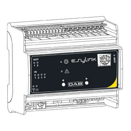
    Blinkend: e.sylink nicht angeschlossen, je- doch mit präsenter Wireless-Konfiguration Grün Drucksensor angeschlossen Tabelle 4: Merkmale der LEDS In der Tabelle 5 werden die mit e.sylink möglichen Anomalien beschrieben. Abbildung 5: Schnittstelle An e.sylink befinden sich LEDS, die den Betriebsstatus des Systems Fault LED FAULT anzeigen.
  • Seite 30: Zuordnungsverfahren

    Aktualisierungsverfahren Datei .bin am e.sylink: e.sybox verbunden werden kann. Um die Firmware von e.sylink zu wechseln oder e.sybox mit einer Es ist möglich e.sylink an eine e.sybox oder mehrere e.sybox anzu- neueren Version zu aktualisieren, wird die Datei .bin mit der neuesten schließen, indem die folgende Prozedur befolgt wird:...
  • Seite 31 Um weitere e.sybox zu aktualisieren, diesen Vorgang wie- derholen Falls die Aktualisierung nicht erfolgt ist, leuchtet am e.sylink die rote LED Fault. In der Tabelle 1 ist angegeben, wie oft die LED FAULT des e.sylink im Falle von Fehlern blinkt und wie jeweils vorzugehen ist. Fehlercode Ursache...
  • Seite 32: Waarschuwingen

    De e.sylink is de accessoire van DAB met een draadloze interface zondheid van personen en beschadiging van de apparatuur.
  • Seite 33: Technische Gegevens

    NEDERLANDS 1.1 Technische gegevens De e.sylink heeft 4 optisch geïsoleerde digitale ingangen (connector J3), 2 relaisuitgangen met arbeidscontact (connector J15), en beschikt over een ingang voor 1 remote druksensor (J31). Voedingsspanning 24 V ± 20% Er zijn 10 leds als gebruikersinterface aanwezig en 2 toetsen.
  • Seite 34 NEDERLANDS Uitgangscontacten: Bedrading ingangen De verbindingen van de hieronder genoemde uitgangen verwijzen naar het 9-polige klemmenbord (J15) en worden aangegeven met Ingang verbonden met potentiaalvrij Ingang onder de zeefdrukken O1, O2 en CA. In Tabel 3 worden de kenmerken en contact spanning limieten van de uitgangscontacten beschreven.
  • Seite 35 Maak nu de verbinding met een of meer e.sybox’en, zoals beschreven is in hoofdstuk 3. LET OP: om de e.sylink te kunnen verbinden met de e.sybox moet worden nagegaan of de FW-versie van de e.sybox 4.xx of hoger is. Zie de installatiehandleiding van de e.sybox om de FW-versie te con-...
  • Seite 36 Afbeelding 5: e.sylink interface In Tabel 5 worden de mogelijke storingen beschreven die kunnen Op de e.sylink zitten leds waarmee de bedrijfsstatus van het systeem worden geconstateerd door e.sylink wordt aangegeven. In Tabel 4 wordt de betekenis van iedere leds die...
  • Seite 37 5 seconden op de toets ‘+’, wacht tot de blauwe 1 - Schakel de e.sylink in door een willekeurige toets ingedrukt te houden blauwe led (op het e.sybox-display) om de 2 seconden knippert. 2 - Op de pc verschijnt het e.sylink schijfstation •...
  • Seite 38 Herhaal deze procedure om andere e.sybox’en te updaten Als de update niet heeft plaatsgevonden, gaat op de e.sylink de rode storingsled (Fault) branden. Tabel 1 beschrijft het aantal knippersignalen van de FAULT-led wan- neer er fouten zijn, en de actie die moet worden ondernomen.
  • Seite 39: Datos Generales

    El incumplimiento de las normas de seguridad, además de e.sylink es el accesorio DAB dotado de interfaz inalámbrica 802.15.4, ser peligroso para las personas y dañar los equipos, provoca realizado para que e.sybox funcione con entradas digitales (preso- la caducidad de la garantía.
  • Seite 40: Datos Técnicos

    ESPAÑOL 1.1 Datos técnicos e.sylink está dotado de 4 entradas digitales optoaisladas (conector J3) , 2 salidas relé NO (normalmente abierto) (conector J15) y una entrada destinada a 1 sensor de presión remoto (J31). Tensión de alimentación 24 V ± 20% Está...
  • Seite 41 ESPAÑOL Contactos de salida: Cableado de las entradas Las conexiones de las salidas enumeradas a continuación tienen como referencia el terminal de bornes de 9 polos (J15) indicadas con Entrada en Entrada conectada a contacto limpio la serigrafía O1, O2 y CA. La tabla 3 describe las características y tensión límites de los contactos de salida.
  • Seite 42 Para disponer de ejemplos de aplicaciones prácticas implementables en e.sylink, consultar el manual de instalación de e.sybox. Sensor de presión: e.sylink permite el uso de 1 sensor de presión remoto directamente en el conector de 4 polos J31. Para más informaciones consultar el manual de instalación relativo a e.sybox.
  • Seite 43: Interfaz De Usuario

    Figura 5: Interfaz de e.sylink ración inalámbrica presente e.sylink está provisto de leds para indicar el estado de funcionamiento Verde Sensor de presión conectado del sistema. La tabla 4 describe el significado de cada leds incorpora- do en la interfaz de usuario: Tabla 4: Características de los leds...
  • Seite 44 Conectando e.sylink al PC con el cable USB en equipamiento, se visuali- Versión de protocolo wireless 1 parpadeo cada 4 segundos zará en su interior un fichero.bin que contiene el firmware de e.sylink y el no compatible firmware para poder actualizar e.sybox. El fichero será de tipo EsyBox_ Vxxx.yy_EsyLink_Vkkk.zz.bin, donde xxx.yy representa la versión fw de...
  • Seite 45 ESPAÑOL De no haberse realizado la actualización, en encenderá en el e.sylink en la Apagar la bomba e.sybox que se desea actualizar el led rojo de fallo. centralita Colocar la centralita e.sylink en proximidad de la e.sybox e.sylink La Tabla 1 describe el número de parpadeos del led FALLO de e.sylink en caso de errores y las acciones a efectuar.
  • Seite 46: Ostrzeżenia

    1- INFORMACJE OGÓLNE unieważnia wszelkie prawo do pomocy w ramach gwarancji. e.sylink jest akcesorium DAB z bezprzewodowym interfejsem 802.15.4, Wykwalifikowany personel zaprojektowanym tak, aby umożliwić e.sybox wykorzystanie wejść Wskazane jest, aby instalacja została przeprowadzona cyfrowych (czujnik ciśnienia, pływak, itd.), do sterowania 2 wyjściami...
  • Seite 47: Dane Techniczne

    POLSKI 1.1 Dane techniczne e.sylink posiada 4 optoizolowane wejścia cyfrowe (konektor J3), 2 NO (normalnie otwarte) wyjścia przekaźnikowe (konektor J15) i ma wyjście na 1 czujnik zdalnego ciśnienia (J31). Istnieje 10 LED dla Napięcie zasilania 24 V ± 20% interfejsu użytkownika i 2 klawisze.
  • Seite 48 POLSKI Styki wyjściowe: Podłączenie wejść Połączenia wyjść wymienione poniżej odnoszą się do 9-biegunowej listwy zaciskowej (J15), oznaczonej sitodrukiem O1, O2 i CA. Wejście podłączone do czystego Napięcie wejścia Tabela 3 opisuje cechy i limity styków wyjściowych. styku Oczyścić kontakt Charakterystyka styków wyjściowych Wejście Zworka Połączenie...
  • Seite 49 Teraz nawiązać połączenie z jednym lub więcej e.sybox, jak to opisa- no w rozdziale 3. UWAGA: W celu połączenia e.syLink do e.syBox sprawdzić, czy wer- sja FW e.sybox to 4.xx czy nowsza. Aby sprawdzić wersję FW, należy zajrzeć do instrukcji montażu e.sybox. W przypadku poprzedniej...
  • Seite 50: Interfejs Użytkownika

    Tabella 4: Opis diod LED Rys. 5: interfejs e.sylink Tabela 5 opisuje ewentualne błędy, które mogą być wykryte przez Na e.sylink są diody LED informujące o stanie pracy systemu. e.sylink Tabela 4 opisuje znaczenie poszczególnych diod LED w interfejsie Błąd BŁĄD LED...
  • Seite 51 POLSKI Procedura powiązywania fw e.sybox, podczas gdy kkk.zz oznacza wersję fw e.sylink. Podstawową funkcją e.sylink jest to, że może on być połączony za Procedura aktualizacji pliku bin na e.sylink pomocą interfejsu bezprzewodowego 802.15.4, wyposażonego w Aby zmienić oprogramowanie e.sylink lub aktualizować e.sybox protokół...
  • Seite 52 Powtórzyć tę procedurę, aby aktualizować inne jednostki e.sybox. Jeśli udało się poprawnie przeprowadzić aktualizację, zaświeci się czerwona dioda LED na e.sylink. Tabela 1 przedstawia liczbę mignięć w e.sylink diod LED w przypadku błędów, oraz działania jakie należy podjąć. Kod błędu Przyczyna Niezbędne działania...
  • Seite 53: Legenda K Symbolům

    UPOZORNĚNÍ 1- VŠEOBECNÉ INFORMACE Před započetím instalace si pečlivě prostudujte tento návod. E.SYLINK je příslušenství DAB s bezdrátovým interface 802.15.4, Instalace a provoz musí být v souladu s bezpečnostními navržené pro použití digitálních vstupů čerpadla E.SYBOX (tlakové normami a pravidly platnými v zemi, kde je zařízení instalováno.
  • Seite 54 Obrázek 1: e.sylink připojením signálu I k nějakému kontaktu (např. plováku, tlakovému spínači, atd.). E.SYLINK je vybaven 4 optickými izolovanými digitálními vstupy (konektor J3), 2 NO (bez proudu otevřeno) reléovými výstupy (konek- Zapojení vstupů tor J15) a má výstup pro 1 externí tlakové čidlo (J31).
  • Seite 55 ČEŠTINA (J15), označené sítotiskem O1, O2 a CA. Prázdný kontakt mezi Tabulka 3 popisuje charakteristiky a limity výstupních kontaktů. Vstup Propojka Připojení svorkami I1-VS CB - GND I1 - CB Charakteristiky výstupních kontaktů I2-VS CB - GND I2 - CB NO (bez proudu Typ kontaktu otevřeno)
  • Seite 56: Instalace

    žádaná nastavení vstupů a výstupů na čerpadle E.SYBOX (viz instalační manuál k E.SYBOXU). Poté připojte E.SYLINK k napájecímu napětí dle schématu na obrázku 4. Obrázek 4 ukazuje, pouze jako příklad, přívodní vodič používající 24 VDC napájecí zařízení pro montáž na montážní lištu.
  • Seite 57: Uživatelský Interface

    čidlo Obrázek 5: e.sylink interface Tabulka 4: Charakteristiky LED kontrolek Na zařízení E.SYLINK jsou LED kontrolky signalizující provozní Tabulka 5 popisuje možné poruchy, které mohou být zařízením stav systému. Tabulka 4 popisuje význam každé LED kontrolky na E.SYLINK rozpoznány: uživatelském interface.
  • Seite 58: Jak Aktualizovat E.sylink A E.sybox

    (interface) 802.15.4, vybaveného protokolem dabpumps.com), PC s operačním systémem Windows 7, Vista nebo DAB, k jedné či více E.SYBOX jednotkám. XP a USB kabel s konektorem typu B dodávaný společně s E.SYLINK E.SYLINK je možné připojit k jednomu E.SYBOXU nebo k několika zařízením.
  • Seite 59 Pro aktualizaci dalších E.SYBOX jednotek opakujte tento postup. Pokud nebyla tato aktualizace úspěšná, na E.SYLINKU se rozsvítí červená LED kontrolka pro signalizaci PORUCHY. Tabulka 1 popisuje počet zablikání E.SYLINK LED kontrolky pro signalizaci PORUCH v případě chyby a také akci, která musí být provedena. Kód chyby Příčina...
  • Seite 60 Tel. +48 223 81 6085 Tel. +38 044 391 59 43 PC: 266500 Tel. +36.93501700 info.china@dwtgroup.com Tel.: +8653286812030-6270 DAB PUMPS DE MÉXICO, S.A. DE C.V. Fax: +8653286812210 Av Gral Álvaro Obregón 270, officina 355 Hipódromo, Cuauhtémoc 06100 México, D.F. Tel. +52 55 6719 0493 DAB PUMPS S.p.A.

Inhaltsverzeichnis