Herunterladen Inhalt Inhalt Diese Seite drucken
Velleman VMM502 Bedienungsanleitung

Velleman VMM502 Bedienungsanleitung

Micro:bit tinker kit

Werbung

Verfügbare Sprachen
  • DE

Verfügbare Sprachen

  • DEUTSCH, seite 82

Werbung

Inhaltsverzeichnis
loading

Inhaltszusammenfassung für Velleman VMM502

  • Seite 1: Inhaltsverzeichnis

    VMM502 MICRO:BIT TINKER KIT USER MANUAL HANDLEIDING MODE D'EMPLOI MANUAL DEL USUARIO BEDIENUNGSANLEITUNG INSTRUKCJA OBSŁUGI MANUAL DO UTILIZADOR...
  • Seite 2: Safety Instructions

     Nor Velleman nv nor its dealers can be held responsible for any damage (extraordinary, incidental or indirect) – of any nature (financial, physical…) arising from the possession, use or failure of this product.
  • Seite 3: Getting Started

    VMM502 Description This starter kit is an educational kit based on micro:bit. It comes with basic electronic components, a breadboard, connection wires and a micro:bit. Getting Started The programme is written in code blocks, online in the web browser. Open the website www.makecode.com...
  • Seite 4 VMM502 You can see the editor is made up of different sections. You make your code in the Code Area, dragging out blocks from the Code Drawer. You can immediately see your code results in the micro:bit simulator. At the bottom is where you download and save your project.
  • Seite 5 VMM502 Shortcuts to changing project properties. Rename and delete your projects here. Reset deletes all the projects that you have saved, so be very careful. Most of the time, you will just want to stick to Delete Project. Using the LED Bar We start by writing some code! Each time you select from the Code Drawer, it will list all the codes available to you.
  • Seite 6 VMM502 Say Hello! The text you have been displaying are called strings. You can show any integer in the LED screen using show number or any 5x5 pixel image using show leds. You can also plot one point LED at the time using co-ordinates. Co-ordinate (0,0) is the top left corner.
  • Seite 7 VMM502 Testing on micro:bit Connect the micro;bit to your computer using a micro-USB cable. It will go through a default sequence, asking you to press buttons and play a game. Try it out! Click Download to translate your script to a hex file and to download it.
  • Seite 8 VMM502 Parts – Kit 1. Breakout board (BoB) 4. Passive buzzer Plug in your micro:bit and play with different Because the micro:bit cannot Make sound on its sensors and outputs. own. 2. Mini servo 5. LED module Make arms and legs, and make them move! 25 RGB LEDs.
  • Seite 9 VMM502 10. ADKeypad Many buttons! Projects Project 1 – Music Machine Let’s make some music! micro-USB cable micro:bit ADKeypad passive buzzer What do I need?  1x micro:bit  1x micro-USB cable  1x BoB  1x mini buzzer ...
  • Seite 10 VMM502 Step 2  Connect the buzzer to P0 on the BoB.  Connect the ADKeypad to P2 on the BoB.  Make sure for all components that the colour of the wires matches the colour of the pins on the breakout board.
  • Seite 11 VMM502 Step 4  Click on Tinkercademy OLED inside the Code Drawer to find our custom blocks for the various components in your kit.  Next, let’s create a conditional statement if then else as shown in the picture. You will find this block in Logic section of the Code Drawer.
  • Seite 12 VMM502 Project 2 – Smart Light A smart light for smart Tinkerers! micro-USB cable micro:bit PIR sensor What do I need?  1x micro:bit  1x micro-USB cable  1x BoB  1x PIR sensor  1x LED  2x female-female jumper wires Let’s get started!
  • Seite 13 VMM502 Step 2 – Pre-Coding Refer to Project 1, Step 3 – Pre-Coding. Step 3 – Coding  Click on Tinkercademy inside the Code Drawer to find our custom blocks for the various components in your kit.  Next, let’s create a code as shown in the picture. For this project, no initialisation is required and there isn’t much code anyway.
  • Seite 14 VMM502 Now, drag and drop the block toggle LED at pin P0 Off next the then logic. Set pin P0 to P1 and set Off to ON. Finally, drag and drop the block toggle LED at pin P0 Off next to the else logic.
  • Seite 15 VMM502 Let’s get started! Step 1  Insert the micro:bit into the BoB.  Connect the crash sensor to pin 0 (P0), the green LED to pin 4 (P4) and the red LED to pin 1 (P1) using the jumper wires Make sure for all components that the colour of the wires matches the colour of the pins on the breakout board.
  • Seite 16 VMM502  Click on Tinkercademy OLED inside the Code Drawer to find our custom blocks for the various components in your kit. Step 3 – Coding  Use blocks under the Tinkercademy OLED section, to initialize the OLED and crash sensor as shown in the picture below.
  • Seite 17 VMM502 The block show string can be found in the OLED in Code Drawer. The digital write pin P0 to 0 block can be found in the Advanced Pins in the Code Drawer.  Since there are only two conditions, we need only one else if statement.
  • Seite 18 VMM502 Let’s get started! Step 1  Insert the micro:bit into the BoB and plug in the micro-USB cable. Then, plug in the OLED as shown. You should be able to plug it into any of the three rows. ...
  • Seite 19 VMM502 Step 3 – Coding  Drag and drop the blocks as shown below in picture.  You should always initialize the OLED at the beginning. 64 and 128 represent the height and width of the OLED respectively. The block...
  • Seite 20 © COPYRIGHT NOTICE The copyright to this manual is owned by Velleman nv. All worldwide rights reserved. No part of this manual may be copied, reproduced, translated or reduced to any electronic medium or otherwise without the prior written consent of the copyright holder.
  • Seite 21: Veiligheidsvoorschriften

     Noch Velleman nv noch zijn verdelers kunnen aansprakelijk gesteld worden voor schade (buitengewoon, incidenteel of onrechtstreeks) – van welke aard dan ook (financieel, fysisch…) voortvloeiend uit het bezit, gebruik of falen van dit product.
  • Seite 22: Aan De Slag

    VMM502 Omschrijving Deze kit is een educatieve kit gebaseerd op micro:bit. Deze kit wordt geleverd met elektronische componenten, een breadboard, aansluitkabels en een micro:bit. Aan de slag Het programma is geschreven m.b.v. codeblokken, online in de webbrowser. Ga naar de website www.makecode.com...
  • Seite 23 VMM502 De editor bestaat uit verschillende secties: Maak uw code in het Codevelddoor blokken te slepen uit het menu Code Drawer. Het resultaat van de code verschijnt onmiddellijk in de micro:bit simulator. Met de knop Download (onderaan de pagina) kunt u de code downloaden en naar de micro:bit uploaden.
  • Seite 24 VMM502 Klik op het tandwielicoontje om projectinstellingen te bewerken. Via dit menu kunt u uw projecten een andere naam geven en verwijderen. Reset verwijdert alle opgeslagen projecten, wees dus voorzichtig. In de meeste gevallen gebruiken Delete Project. Het ledscherm gebruiken We beginnen met het schrijven van een code! Telkens u een blok uit het menu selecteert, worden alle beschikbare codes weergegeven.
  • Seite 25 VMM502 Say Hello! De stukjes tekst die verschijnen, zijn strings. U kunt een willekeurig getal weergeven met show number of een 5x5 pixel afbeelding op het scherm weergeven met de show leds. U kunt ook x- en y-coördinaten gebruiken om een specifieke led in het raster te gebruiken. De coördinaten (0.0) bevinden zich linksboven.
  • Seite 26 VMM502 Op de micro:bit testen Sluit de micro:bit aan op de computer met een micro-USB-kabel. Een testroutine verschijnt op de micro:bit waarbij u wordt gevraagd om op knoppen te drukken en een spel te spelen. Probeer het uit! Klik op...
  • Seite 27 VMM502 Componenten – Kit 1. Breakout-board (BoB) 4. Passieve zoemer Sluit de micro:bit aan en gebruik verschillende Omdat de micro:bit geen geluid kan produceren. sensoren en uitgangen. 5. Ledmodule 2. Miniservo 25 RGB-leds Maak armen en benen en laat ze bewegen! 3.
  • Seite 28: Crashsensor (Eindeloopsensor)

    VMM502 7. Crashsensor (eindeloopsensor) 9. Potentiometer Het kan een knop zijn, maar veel gemakkelijker Draai aan de knop om aan te sturen. om in te drukken. Detecteert botsingen met een obstakel. 10. ADKeypad Veel knoppen! Projecten Project 1 – Music Machine Laten we wat muziek maken! V.
  • Seite 29 VMM502 micro-USB-kabel micro:bit ADKeypad passieve zoemer Wat heb ik nodig?  1x micro:bit  1x micro-USB-kabel  1x BoB  1x mini zoemer  1x ADKeypad  2x draadbruggen (vrouwelijk-vrouwelijk) Aan de slag! Stap 1  Sluit het ene uiteinde van de micro-USB-kabel aan op de pc en sluit het andere uiteinde op de micro:bit aan.
  • Seite 30 VMM502 Stap 2  Sluit de zoemer aan op de P0-pin van de BoB.  Sluit het ADKeypad aan op de P2-pin van de Bob.  Zorg ervoor dat de kleuren van de draden overeenkomen met de kleuren van de pinnen op het breakout-board.
  • Seite 31 VMM502 Stap 4  Klik op Tinkercademy OLED in het menu om de codeblokken voor de verschillende componenten weer te geven.  Vervolgens voegen we een voorwaarde if then else toe (zie afb.). Deze blok bevindt zich in het menu onder Logic.
  • Seite 32 VMM502  U kunt nu muziek maken door de knoppen van de ADKeypad in te drukken! Veel plezier! Project 2 – Smart Light Een slim ledlampje maken! micro-USB-kabel micro:bit PIR-sensor Wat heb ik nodig?  1x micro:bit  1x micro-USB-kabel ...
  • Seite 33 VMM502 Step 2 – Voorprogrammeren Zie Project 1, Step 3 – Voorprogrammeren. Step 3 – Programmeren  Klik op Tinkercademy in het menu om de codeblokken voor de verschillende componenten weer te geven.  Laten we een code maken zoals in de afbeelding hieronder. Voor dit project is geen installatie vereist en is er niet veel code.
  • Seite 34 VMM502 Sleep het blokje if then else onder het blokje forever. Het blokje if then else bevindt zich onder Logic in het menu. Voeg het blok motion detector at pin detects motion naast het blokje if. Vervang het blokje true. De blokjes schuiven in elkaar. Het blokje...
  • Seite 35 VMM502 Sleep het blokje toggle LED at pin P0 Off naast het blokje then. Stel pin P0 in als P1 en stel Off in als ON. Sleep het blokje toggle LED at pin P0 Off naast het blokje else. Stel pin P0 in als P1.
  • Seite 36 VMM502 Aan de slag! Stap 1  Steek de micro:bit in de BoB.  Sluit de crashsensor (eindeloopsensor) aan op pin 0 (P0), de groene led op pin 4 (P4) en de rode led op poin 1 (P1) met de draadbruggen. Zorg ervoor dat de kleuren van de draden van de componenten overeenkomen met de kleuren van de pinnen op het breakout-board.
  • Seite 37 VMM502  Klik op Tinkercademy OLED in het menu om de codeblokken voor de verschillende componenten weer te geven. Step 3 – Programmeren  Gebruik de blokken onder Tinkercademy OLED om het oledscherm en crashsensor te initialiseren zoals in de afbeelding hieronder.
  • Seite 38 VMM502 Het blok show string bevindt zich onder OLED in het menu. Het blok digital write pin P0 to 0 bevindt zich onder Advanced Pins in het menu.  Aangezien er maar twee voorwaarden zijn, is er maar 1 blokje else if nodig.
  • Seite 39 VMM502 Aan de slag! Stap 1  Steek de micro:bit in de BoB en sluit de micro-USB-kabel aan. Sluit het oledscherm aan als volgt. U kunt deze aansluiten op één van de drie rijen.  Sluit de zoemer aan op pin 0 (P0).
  • Seite 40 VMM502 Step 3 – Programmeren  Sleep de blokken zoals in de afbeelding hieronder.  Initialiseer altijd het oledscherm bij het opstarten. 64 en 128 stellen de hoogte en breedte van het oledscherm weer. Het blokje if then else bevindt zich onder Logic in het menu.
  • Seite 41 Your plant is in good conditionop het oledscherm. Gebruik dit toestel enkel met originele accessoires. Velleman nv is niet aansprakelijk voor schade of kwetsuren bij (verkeerd) gebruik van dit toestel. Voor meer informatie over dit product en de laatste versie van deze handleiding, zie www.velleman.eu.
  • Seite 42: Mode D'emploi

     Ni Velleman SA ni ses distributeurs ne peuvent être tenus responsables des dommages exceptionnels, imprévus ou indirects, quelles que soient la nature (financière, corporelle, etc.), causés par la possession, l’utilisation ou le dysfonctionnement de ce produit.
  • Seite 43: Mise En Service

    VMM502 Description Ce kit est un kit éducatif basé sur micro:bit. Le kit comporte des composants électroniques, une platine d'expérimentation, des câbles de connexion et un micro:bit. Mise en service La programmation se fait en ligne à partir d'un navigateur web par blocs. Accéder au site www.makecode.com...
  • Seite 44 VMM502 L'éditeur se compose en différent volets : Créer le code dans l'espace de travail Code Area, avec des blocs à glisser-déposer depuis le menu. Le résultat du code s'affiche en temps réel dans le simulateur. En bas de l'écran, le bouton Download permet de télécharger et sauvegarder votre projet.
  • Seite 45 VMM502 Cliquer sur l'icône d'engrenage pour modifier les paramètres du projet. Depuis ce menu, il est possible de renommer et supprimer vos projets. Reset/Remise à zéro supprimera tous les projets enregistrés. Faire attention. Il est généralement préférable d’utiliser Supprimer un projet.
  • Seite 46 VMM502 Say Hello! Les caractères affichés sont des chaînes de caractères. Vous pouvez afficher du texte et des numéros en utilisant la fonction show number ou une image de 5x5 pixels avec show leds. Vous pouvez également allumer et éteindre une seule LED avec des coordonnées. Les coordonnées (0,0) se trouvent en haut à...
  • Seite 47 VMM502 Tester sur le micro:bit Connecter le micro:bit à votre PC avec un câble micro-USB. Une routine de test s'affiche sur le micro:bit, vous demandant d'appuyer sur des boutons et de jouer un jeu. Tester le ! Cliquer sur Download pour convertir le script en un fichier .hex...
  • Seite 48 VMM502 Composants - Kit 1. Carte breakout (BoB) 4. Ronfleur passif Insérer le micro:bit et utiliser différents capteurs Puisque le micro:bit n'émet pas de son. et sorties. 5. Module LED 2. Mini-servo 25 LED RGB. Créer des bras et des jambes et faire les bouger ! 3.
  • Seite 49 VMM502 7. Capteur de collision (interrupteur fin de 9. Potentiomètre course) Faire tourner le bouton pour le réglage. Ce pourrait être un bouton, mais beaucoup plus facile à appuyer. Idéal pour indiquer si le robot a touché un obstacle. 10. Clavier AD...
  • Seite 50 VMM502 câble micro-USB BoB (carte breakout) micro:bit Clavier AD ronfleur passif De quoi ai-je besoin ?  1x micro:bit  1x câble micro-USB  1x carte breakout (BoB)  1x mini-ronfleur  1x clavier AD  2x fils de connexion femelle-femelle Démarrer !
  • Seite 51 VMM502 Étape 2  Connecter le ronfleur à la broche P0 de la carte breakout.  Connecter le clavier AD à la broche P2 de la carte breakout.  S'assurer que la couleur des fils correspond à la couleur des broches sur la carte breakout.
  • Seite 52 VMM502 Etape 4  Cliquer sur Tinkercademy OLED dans le menu pour visualiser les blocs ajoutés des différents composants.  Créons une instruction conditionnelle if then else (voir ill.). Ce bloc se trouve dans le menu sous Logic.  Le code affiché ci-dessous signifie que le ronfleur émettra un son de 175 Hz lorsque vous appuyez sur bouton A pendant que le clavier AD connecté...
  • Seite 53 VMM502  Maintenant, vous pouvez jouer de la musique en appuyant sur les touches du clavier AD. Amusez- vous ! Projet 2 – Smart Light Créer une lumière intelligente ! câble micro-USB BoB (carte breakout) micro:bit capteur PIR De quoi ai-je besoin ? ...
  • Seite 54 VMM502 Etape 2 – Préprogrammer Voir Projet 1, Etape 3 – Préprogrammer. Etape 3 – Programmer  Cliquer sur Tinkercademy dans le menu pour visualiser les blocs ajoutés des différents composants du kit.  Créons un code comme indiqué. Pour ce projet, aucune initialisation n'est requise et il n'y a pas beaucoup de code.
  • Seite 55 VMM502 Glisser-déposer le bloc if then else sous le bloc forever dans le menu. Le bloc if then else se trouve dans le menu sous Logic. Puis, déposer le bloc motion detector at pin detects motion à côté du bloc if. Remplacer le bloc true.
  • Seite 56 VMM502 Glisser-déposer le bloc toggle LED at pin P0 Off à côté du bloc then. Régler la broche P0 sur P1 et régler Off sur ON. Ensuite, glisser-déposer le bloc toggle LED at pin P0 Off à côté du bloc else. Régler la broche P0 sur Lorsque le capteur PIR détecte du mouvement, la lumière (LED) s'allume.
  • Seite 57 VMM502 Démarrer ! Etape 1  Insérer le micro:bit dans la carte breakout (BoB).  Connecter le capteur de collision à la broche 0 (P0), la LED verte à la broche 4 (P4) et la LED rouge à la broche 1 (P1) à l'aide des fils de connexion. S'assurer que la couleur des fils correspond à la couleur des broches de la carte breakout.
  • Seite 58 VMM502  Cliquer sur Tinkercademy OLED dans le menu pour visualiser les blocs ajoutés des différents composants du kit. Etape 3 – Programmer  Utiliser les blocs sous Tinkercademy OLED pour initialiser l'écran OLED et le capteur de collision (voir ci-dessous).
  • Seite 59 VMM502 Le bloc show string se trouve dans le menu sous OLED. Le bloc digital write pin P0 to 0 se trouve dans le menu sous Advanced  Pins. Comme il n'y a que deux conditions, il nous faut seulement une instruction conditionnelle else Lorsque le capteur de collision est active, la LED verte s'allume.
  • Seite 60 VMM502 Démarrer ! Etape 1  Insérer le micro:bit dans la carte breakout (BoB) et connecter le câble micro-USB. Connecter l'écran OLED comme suit. Connecter le à l'une des trois lignes.  Connecter le ronfleur à la broche P0. ...
  • Seite 61 VMM502 Etape 3 - Programmer  Glisser-déposer les blocs comme indiqué.  Toujours initialiser l'écran OLED au démarrage. 64 et 128 représentent la hauteur et la largeur de l'écran OLED. Le bloc if then else se trouve dans le menu sous Logic.
  • Seite 62 être modifiés sans notification préalable. © DROITS D’AUTEUR Velleman SA est l’ayant droit des droits d’auteur de ce mode d'emploi. Tous droits mondiaux réservés. Toute reproduction, traduction, copie ou diffusion, intégrale ou partielle, du contenu de ce mode d'emploi par quelque procédé ou sur tout support électronique que ce soit est interdite sans l’accord préalable écrit de l’ayant droit.
  • Seite 63: Instrucciones De Seguridad

     Ni Velleman nv ni sus distribuidores serán responsables de los daños extraordinarios, ocasionales o indirectos, sea cual sea la índole (financiera, física, etc.), causados por la posesión, el uso o el fallo de este producto.
  • Seite 64: Primeros Pasos

    VMM502 Función Este kit para principiantes es un kit educativo que se basa en el sistema micro:bit. Lleva componentes electrónicos básicos, una placa de pruebas, cables de conexión y un micro:bit. Primeros pasos El programa lleva bloques de programación y se puede ejecutar en línea. Introduzca en el navegador la dirección...
  • Seite 65 VMM502 El editor lleva diferentes secciones. Puede crear su código en el área de programación, arrastrando los bloques desde el menú de bloques. En el simulador micro:bit podrá comprobar el funcionamiento del programa. En la parte inferior puede descargar y almacenar el proyecto.
  • Seite 66 VMM502 Sección de configuración Aquí es posible cambiar el nombre del proyecto y borrarlo. Reset/Restablecer: con esta opción borrará todos los proyectos guardados. ¡Tenga cuidado! La mayoría de las veces, sólo necesitará la opción Delete Project/Eliminar proyecto. Barra de LEDs Vamos a crear un código.
  • Seite 67 VMM502 Say Hello! El texto visualizado se llama string/cadena. Con la función show number/mostrar número se visualizarán números enteros en la pantalla LED. Con la función show leds/mostrar LEDs se visualizará una imagen de 5x5 píxeles. También puede iluminar un punto LED con coordenadas. La Coordenada (0,0) está en la esquina superior izquierda.
  • Seite 68 VMM502 micro:bit Conecte la micro:bit al ordenador con el cable micro-USB. Se ejecutará una secuencia por defecto. Se le pedirá que pulse botones y juegue un juego. ¡Pruébelo! Haga clic en Download/Descargar para convertir su texto en un fichero hex y descargarlo.
  • Seite 69 VMM502 Piezas – Kit 1. Tarjeta Breakout (BoB) 4. Zumbador pasivo Permite jugar con diferentes sensores y salidas al Permite hacer que el micro:bit emita una señal conectarla al micro:bit. acústica. 2. Mini servo 5. módulo LED Permite crear brazos y pies y hacer que se 25 LEDs RGB muevan.
  • Seite 70 VMM502 10. Teclado ADKeypad ¡Muchos botones! Proyectos Proyecto 1 – Caja de música ¡Vamos a crear música! cable micro-USB tarjeta breakout (BoB) micro:bit teclado ADKeypad zumbador pasivo Lo que necesita  1x micro:bit  1x cable micro-USB  1x tarjeta breakout (BoB) ...
  • Seite 71 VMM502 Paso 2  Conecte el zumbador al PO de la tarjeta breakout (BoB).  Conecte el teclado ADKeypad al P2 de la tarjeta breakout (BoB).  Asegúrese para cada componente de que el color de los cables coincida con el color de los pins de la tarjeta breakout (BoB).
  • Seite 72 VMM502 Paso 4  En el menú, haga clic en el menú bajo Tinkercademy OLED para encontrar los diferentes bloques para los diferentes componentes del kit.  Ahora, vamos a crear el condicional if then else/si entonces si no (véase la fig.). Este bloque se sitúa en el menú...
  • Seite 73 VMM502 Proyecto 2 – Luz inteligente Una luz inteligente para Tinkerers inteligentes. cable micro-USB tarjeta breakout (BoB) micro:bit sensor PIR Lo que necesita  1x micro:bit  1x cable micro-USB  1x tarjeta breakout (BoB)  1x sensor PIR ...
  • Seite 74 VMM502 Paso 2 – Preprogramación Consulte Proyecto 1, Paso 3 – Preprogramación. Paso 3 – Programación  En el menú, haga clic en el menú bajo Tinkercademy para ver los diferentes bloques de código hechos a medida para los diferentes componentes del kit.
  • Seite 75 VMM502 Ahora, arrastre y suelte el bloque toggle LED at pin P0 Off junto al bloque then/entonces. Coloque pin P0 en P1 y coloque Off en On. Finalmente, arrastre y suelte el bloque toggle LED at pin P0 Off junto al bloque else/si no.
  • Seite 76 VMM502 ¡Vamos a ello! Paso 1  Fije el micro:bit a la tarjeta breakout (BoB).  Conecte el sensor de impacto al pin 0 (P0), el LED verde al pin 4 (P4) y el LED rojo al pin 1 (P1) con los cables de puente.
  • Seite 77 VMM502  En el menú, haga clic en el menú bajo Tinkercademy OLED para ver los diferentes bloques de código hechos a medida para los diferentes componentes del kit. Paso 3 – Programación  Utilice los bloques bajo Tinkercademy OLED para encender la pantalla OLED y el sensor de impacto (véase la fig.).
  • Seite 78 VMM502 El bloque show string se sitúa en el menú bajo OLED. El bloque digital write pin P0 to 0 se sitúa en el menú bajo Advanced  Pins. Como hay sólo dos condiciones, necesitaremos sólo un bloque else if/si no.
  • Seite 79 VMM502 ¡Vamos a ello! Paso 1  Fije el micro:bit a la tarjeta breakout y conecte el cable micro-USB. Fije la pantalla OLED (véase fig.). Debería ser capaz de conectarla en una de las tres filas.  Conecte el zumbador al pin 0 (P0).
  • Seite 80 VMM502 Paso 3 – Programación  Arrastre y suelte los bloques como se indica en la siguiente figura.  Siempre debería empezar por iniciar la pantalla OLED. 64 y 128 hacen referencia a la altura y al ancho de la pantalla OLED.
  • Seite 81 Your plant is in good condition. Utilice este aparato sólo con los accesorios originales. Velleman NV no será responsable de daños ni lesiones causados por un uso (indebido) de este aparato. Para más información sobre este producto y la versión más reciente de este manual del usuario, visite nuestra página www.velleman.eu.
  • Seite 82: Bedienungsanleitung

    Garantieanspruch. Für daraus resultierende Folgeschäden übernimmt der Hersteller keine Haftung.  Weder Velleman nv noch die Händler können für außergewöhnliche, zufällige oder indirekte Schäden irgendwelcher Art (finanziell, physisch, usw.), die durch Besitz, Gebrauch oder Defekt verursacht werden, haftbar gemacht werden.
  • Seite 83: Beschreibung

    VMM502 Beschreibung Dieser Starter-Kit ist ein Lernbausatz basierend auf micro:bit. Der Bausatz wird mit Basiskomponenten, einer Steckplatine, Anschlusskabel und einem micro:bit geliefert. Erste Schritte Die Programmierumgebung MakeCode ist online verfügbar und bietet eine leicht verständliche Oberfläche, die visuell unterstützte Blockprogrammierung verwendet. Öffnen Sie in einem Browser die folgende URL: www.makecode.com...
  • Seite 84 VMM502 Block-Editor Um einen Code zu kreieren, müssen Sie die Blöcke aus dem Blockmenü (in der Mitte) auf die Programmieroberfläche (links) ziehen. Links oben gibt es den micro:bit-Simulator, wo Sie sofort das Ergebnis sehen können. Unten befindet sich den Button zum Herunterladen und Speichern des Projekts.
  • Seite 85 VMM502 Konfigurationsbereich Projekte einen Namen geben und löschen Reset: mit dieser Option löschen Sie alle gespeicherten Projekte. Seien Sie vorsichtig! Sie benötigen meistens nur die Option Delete Project/Projekt löschen. Die LED-Leiste Lassen wir einen Code schreiben. Im Block-Menü finden Sie alle zur Verfügung stehenden Blöcke. Verschieben...
  • Seite 86 VMM502 Say Hello! Der angezeigte Text nennt man string/Zeichenfolge. Mit der Funktion show number/zeige Nummer werden Ganzzahlen im LED-Bilschirm angezeigt. Mit der Funktion show leds/zeige LEDs wird ein Bild (5x5 Pixel) angezeigt. Sie können auch einen LED-Punkt leuchten lassen, indem Sie Koordinaten verwenden. Die Koordinate (0,0) befindet sich links oben.
  • Seite 87: Zubehörteile - Micro:bit

    VMM502 micro:bit Verbinden Sie den micro:bit über das mitgelieferte mit Micro-USB-Kabel Ihrem Rechner. Standardmäßig wird eine Sequenz wiedergegeben. Es wird Ihn gefragt, Tasten zu drücken und ein Spiel zu spielen. Versuchen Sie! Klicken Sie auf Download/Herunterladen, um para convertir su texto en un fichero hex y descargarlo.
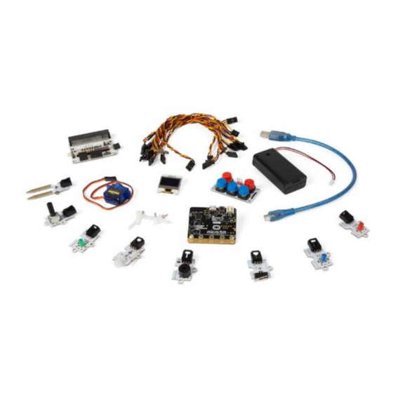
  • Seite 88: Zubehörteile - Kit

    VMM502 Zubehörteile - Kit 1. Breakout-Board (BoB) 4. Passiver Summer Um den micro:bit anzuschließen und mit Um ein akustisches Signal ertönen zu lassen. verschiedenen Sensoren und Ausgängen zu 5. LED-Modul spielen. 25 RGB-LEDs. 2. Mini-Servo Um Arme und Beine zu machen und diese bewegen zu lassen.
  • Seite 89 VMM502 7. Erschütterungssensor 9. Potentiometer Kann einen Button sein, lässt sich aber viel Drehen Sie den Knopf, um Geräte anzusteuern. einfacher drücken. Informiert Ihnen, wenn der Roboter an etwas prallt. 10. Tastatur ADKeypad Viele Tasten! Projekte Projekt 1 – Musikinstrument Lassen wir Musik machen.
  • Seite 90: Schritt 3 - Preprogrammieren

    VMM502 Micro-USB-Kabel Breakout-Board (BoB) micro:bit Tastatur ADKeypad passiver Summer Was sie brauchen  1x micro:bit  1x Micro-USB-Kabel  1x Breakout-Board (BoB)  1x Mini-Summer  1x ADKeypad  2x Steckbrücke, Buchse-Buchse Los geht's! Schritt 1  Verbinden Sie das eine Ende des USB-Kabels mit dem Computer und das andere Ende mit dem micro:bit.
  • Seite 91 VMM502  Sie werden ein Programmpaket hinzufügen müssen, um die Komponenten im Bausatz verwenden zu können. Klicken Sie im Menü auf Advanced/Fortgeschritten und danach auf Add Package Extensions/Erweiterungen.  Folgendes Pop-Up-Fenster erscheint.  Wir brauchen das Programmpaket Tinkercademy. Geben Sie...
  • Seite 92: Projekt 2 - Intelligentes Licht

    VMM502  Kompilieren Sie das Programm und speichern Sie es als .Hex-Datei. Klicken Sie danach auf Download/Herunterladen und speichern Sie die .hex-Datei im Ordner Downloads (C:\downloads). Diese .hex-Datei kann nun auf das micro: bit übertragen werden.  Verbinden Sie den micro:bit über das Micro-USB-Kabel mit dem USB-Port. Verschieben Sie nun die .hex-Datei (im Ordner Downloads) per Drag and Drop in micro:bit...
  • Seite 93 VMM502 Was sie brauchen  1x micro:bit  1x Micro-USB-Kabel  1x Breakout-Board (BoB)  1x PIR-Sensor  1x LED  2x Steckbrücke, Buchse-Buchse Los geht's! Schritt 1  Befestigen Sie den micro:bit am Breakout-Board und verbinden Sie PIR-Sensor mit Pin 0 (P0).
  • Seite 94 VMM502 Verschieben Sie zuerst den Block if then else/wenn dann ansonsten unter den Block forever/dauerhaft. Den Block if then else/wenn dann ansonsten finden Sie im Blockmenü unter Logic/Logik. Setzen Sie den Block motion detector at pin detects motion nun neben den Block if/wenn.
  • Seite 95: Projekt 3 - Einfacher Alarm

    VMM502 Projekt 3 – Einfacher Alarm Lassen Sie einen Alarm ertönen. Micro-USB-Kabel Breakout-Board (BoB) micro:bit Erschütterungssensor OLED Was sie brauchen  1x micro:bit  1x Micro-USB-Kabel  1x Breakout-Board (BoB)  1x Erschütterungssensor  1x OLED  1x LED ...
  • Seite 96 VMM502  Befestigen Sie den OLED-Bildschirm an der Reihe I²C unten am Breakout-Board (siehe Abb.). Schritt 2 – Preprogrammieren Siehe Projekt 1, Schritt 3 – Preprogrammieren.  Klicken Sie auf Tinkercademy oder OLED im Blockmenü, um die Blöcke für die verschiedene Komponenten des Bausatzes zu finden.
  • Seite 97 VMM502 Den Block on start/beim Start finden Sie im Menü unter Basic/Grundlagen . Den Block initialize OLED with height 64 width 128 finden Sie im Blockmenü unter OLED. Den Block setup crash sensor at pin P0 finden Sie im Blockmenü unter Tinkercademy ...
  • Seite 98: Projekt 4 - Eine Pflanze Überwachen

    VMM502 Projekt 4 – Eine Pflanze überwachen Kreieren Sie ein Gerät, um eine Pflanze zu überwachen Micro-USB-Kabel OLED micro:bit Mini-Servo (wird nicht verwendet) passiver Summer Feuchtigkeitssensor Breakout-Board (BoB) Was sie brauchen  1x micro:bit  1x Micro-USB-Kabel  1x Breakout-Board (BoB) ...
  • Seite 99 VMM502 Schritt 2 – Preprogrammieren Siehe Projekt 1, Schritt 3 – Preprogrammieren.  Klicken Sie auf Tinkercademy oder OLED im Blockmenü, um die Blöcke für die verschiedene Komponenten des Bausatzes zu finden. Schritt 3 – Programmieren  Verschieben Sie die Blöcke per Drag and Drop (siehe Abb.).
  • Seite 100 VMM502 Den Block if then else/wenn dann ansonsten finden Sie im Blockmenü unter Logic/Logik. Den Block mit dem Symbol für kleiner als finden Sie im Blockmenü unter Logic/Logik. Verschieben Sie diesen Block neben Block if/wenn. Ersetzen Sie den Block true/wahr. Diese Blöcke werden einrasten.
  • Seite 101 Your plant is in good condition angezeigt. Verwenden Sie dieses Gerät nur mit originellen Zubehörteilen. Velleman NV übernimmt keine Haftung für Schaden oder Verletzungen bei (falscher) Anwendung dieses Gerätes. Mehr Informationen zu diesem Produkt und die neueste Version dieser Bedienungsanleitung finden Sie hier: www.velleman.eu. Alle Änderungen ohne vorherige Ankündigung vorbehalten.
  • Seite 102: Wskazówki Bezpieczeństwa

    Wyłącznie do użytku wewnątrz pomieszczeń. Chronić uchwyt przed deszczem, wilgocią, rozpryskami i ściekającymi cieczami. Informacje ogólne  Proszę zapoznać się z informacjami w części Usługi i gwarancja jakości Velleman ® końcu niniejszej instrukcji.  Przed rozpoczęciem pracy z urządzeniem należy zapoznać się z jego funkcjami.
  • Seite 103 VMM502 Opis Ten zestaw startowy jest zestawem edukacyjnym na bazie micro:bit. Obejmuje podstawowe elementy elektroniczne, płytkę prototypową, kable łączące i moduł micro:bit. Przygotowanie Program jest napisany w blokach kodu, online w przeglądarce internetowej. Otworzyć stronę www.makecode.com lub https://www.microsoft.com/en-us/makecode?rtc=1, kliknąć ikonę micro:bit i kliknąć...
  • Seite 104 VMM502 Można zauważyć, że edytor składa się z różnych sekcji. Kod tworzy się w obszarze Code Area, przeciągając bloki z szuflady kodów Code Drawer. Można od razu zobaczyć wynik działania kodu w symulatorze micro:bit simulator. Na dole znajduje się miejsce pobrania i zapisania projektu.
  • Seite 105 VMM502 Skróty do zmiany właściwości projektu. Tutaj można zmienić nazwę oraz usunąć projekt. Reset kasuje wszystkie zapisane projekty, dlatego należy zachować szczególną ostrożność. Zazwyczaj najlepiej używać Delete Project. Używanie paska LED Rozpoczniemy od napisania kodu! Przy każdym kliknięciu szuflady kodów rozwinie się lista wszystkich dostępnych kodów.
  • Seite 106 VMM502 Say Hello! Wyświetlane teksty nazywane są ciągami strings. Na ekranie LED można wyświetlić dowolną liczbę całkowitą przy użyciu show number lub dowolny obraz 5x5 px przy użyciu show leds. W tym samym czasie można również nanieść jeden punkt LED za pomocą współrzędnych. Współrzędna (0,0) to lewy górny róg.
  • Seite 107 VMM502 Testowanie na micro:bit Podłączyć micro:bit do komputera przy użyciu kabla micro-USB. micro:bit przejdzie przez sekwencję domyślną, prosząc o naciśnięcie przycisków i zagranie w grę. Wypróbuj! Kliknąć Download , aby przełożyć skrypt na plik i pobrać. Przy prawidłowym ustawieniu Chrome, kolejny krok nie będzie konieczny. Przeciągnąć pobrany plik hex na dysk micro:bit lub kliknąć...
  • Seite 108 VMM502 Części – Zestaw 1. Moduł adaptera (BoB) 4. Brzęczyk pasywny Wystarczy podłączyć micro:bit, aby móc się Bez niego micro:bit nie może wydawać bawić różnymi czujnikami i wyjściami. dźwięków. 2. Miniaturowy siłownik 5. Moduł LED Stwórz ręce i nogi, a następnie wpraw je w ruch! 25 diod LED RGB 3.
  • Seite 109 VMM502 7. Czujnik zderzeniowy 9. Potencjometr Zazwyczaj jest to przycisk, ale w ten sposób Sterowanie za pomocą pokrętła. naciśnięcie zostało znacznie ułatwione. Zawsze powiadamia użytkownika, gdy robocik w coś uderzył. 10. Klawiatura AD Dużo przycisków! Projekty Projekt 1 – Maszyna muzyczna Nagrajmy coś!
  • Seite 110 VMM502 kabel micro-USB micro:bit Klawiatura AD brzęczyk pasywny Czego potrzebujemy?  1x micro:bit  1x kabel micro-USB  1x moduł adaptera  1x mini brzęczyk  1x klawiatura AD  2x przewód połączeniowy żeńsko-żeński Do dzieła! Krok 1  Podłączyć jeden koniec kabla USB do komputera, a drugi do micro:bit.
  • Seite 111 VMM502  Pojawi się wyskakujące okienko.  Następnie należy wyszukać Tinkercademy. Wpisać Tinkercademy w polu wyszukiwania i nacisnąć enter.  Kliknąć na pakiet (przycisk) Tinkercademy , aby go pobrać i dodać do szuflady kodów.  Kliknąć przycisk Tinkercademy. Krok 4 ...
  • Seite 112 VMM502  Po ukończeniu skompilowany zostanie program do wygenerowania pliku .hex. Kliknąć przycisk pobierania [download] i zapisać plik .hex w folderze pobierania (C:\Pobrane). Plik .hex jest gotowy do załadowania na micro:bit.  Podłączyć micro:bit do portu USB przy użyciu kabla micro-USB. Następnie przeciągnąć plik .hex (z folderu Pobrane) na urządzenie wymienne...
  • Seite 113 VMM502 Czego potrzebujemy?  1x micro:bit  1x kabel micro-USB  1x moduł adaptera  1x czujnik ruchu PIR  1x LED  2x przewód połączeniowy żeńsko-żeński Do dzieła! Krok 1  Włożyć micro:bit do modułu adaptera i podłączyć czujnik ruchu PIR do pinu 0 (P0).
  • Seite 114 VMM502 Najpierw należy przeciągnąć funkcję logiczną if then else i upuścić w edytorze kodów pod blokiem forever. Blok if then else można znaleźć pod napisem Logic w szufladzie kodów. Następnie dodać blok motion detector at pin detects motion obok układu logicznego if.
  • Seite 115 VMM502 Projekt 3 – Prosta centralka alarmowa Dźwięczna centralka alarmowa! kabel micro-USB micro:bit czujnik zderzeniowy OLED Czego potrzebujemy?  1x micro:bit  1x kabel micro-USB  1x moduł adaptera  1x czujnik zderzeniowy  1x OLED  1x LED ...
  • Seite 116 VMM502 Do dzieła! Krok 1  Włożyć micro:bit do modułu adaptera.  Podłączyć czujnik zderzeniowy do pinu 0 (P0), zieloną diodę LED do pinu 4 (P4) i czerwoną diodę LED do pinu 1 (P1) przy użyciu przewodów połączeniowych. Należy upewnić się, że we wszystkich elementach kolory przewodów są...
  • Seite 117 VMM502 Krok 2 – Kodowanie wstępne Patrz Projekt 1, Krok 3 – Kodowanie wstępne.  Kliknąć na Tinkercademy OLED wewnątrz szuflady kodów Code Drawer, aby wybrać stworzone przez nas bloki dla różnych elementów w zestawie. Krok 3 – Kodowanie ...
  • Seite 118 VMM502 Blok show string znajduje się w sekcji OLED szuflady kodów. Blok digital write pin P0 to 0 znajduje się w sekcji Advanced Pins szuflady kodów.  Potrzebujemy tylko jednego twierdzenia else if, gdyż mamy tylko dwa warunki. Zapali się zielona dioda LED, gdy czujnik zderzeniowy będzie wciśnięty.
  • Seite 119 VMM502 kabel micro-USB OLED micro:bit miniaturowy siłownik (nieużywany) brzęczyk pasywny czujnik wilgotności gleby Czego potrzebujemy?  1x micro:bit  1x kabel micro-USB  1x moduł adaptera  1x brzęczyk pasywny  1x czujnik wilgotności  1x OLED  2x przewód połączeniowy żeńsko-żeński Do dzieła!
  • Seite 120 VMM502 Krok 3 – Kodowanie  Przeciągnąć i upuścić bloki jak na obrazku poniżej.  Zawsze na początku należy przeprowadzić inicjalizację OLED. Wysokość i szerokość OLED wynosi odpowiednio 64 i 128. Blok if then else można znaleźć w sekcji Logic w szufladzie kodów.
  • Seite 121 © INFORMACJA O PRAWACH AUTORSKICH Właścicielem praw autorskich do niniejszej instrukcji jest firma Velleman nv. Wszelkie prawa są zastrzeżone na całym świecie. Żadna część niniejszej instrukcji nie może być kopiowana, powielana, tłumaczona ani przenoszona na jakikolwiek nośnik elektroniczny (lub w inny sposób) bez wcześniejszej pisemnej zgody właściciela praw autorskich.
  • Seite 122: Instruções De Segurança

     Nem Velleman NV nem os seus distribuidores podem ser responsabilizados por quaisquer danos (extraordinário, incidental ou indireto) - de qualquer natureza decorrentes (financeira, física...) a partir da posse, uso ou falha do produto.
  • Seite 123 VMM502 Descrição Este kit de iniciação é um kit educacional baseado no micro:bit. Inclui componentes eletrónicos básicos, uma placa de ensaio, fios de ligação e um micro:bit. Iniciar O programa é escrito em blocos de códigos, online no navegador da web. Aceda ao website www.makecode.com...
  • Seite 124 VMM502 Pode verificar que o editor é composto de diferentes seções. Você cria o seu código na Code Area, arrastando os blocos a partir do Code Drawer. Pode ver o resultado de imediato no micro:bit simulator. Na parte inferior, pode fazer o download e salvar o seu projeto.
  • Seite 125 VMM502 Atalhos para alterar as propriedades do projeto. Altere o nome e apague os seus projetos aqui. Reset apaga todos os projetos que tenha guardado, por isso seja muito cuidadoso. Muitas vezes, apenas procura a opção Delete Project. Usar a Barra LED Começamos por escrever um código! Sempre que seleciona a partir do Desenhador de Código, serão...
  • Seite 126 VMM502 Diga Olá! O texto que acabou de apresentar é chamado de strings. Pode exibir um número inteiro no ecrã LED usando show number ou qualquer imagem de 5x5 pixeis usando show leds. Também pode traçar um LED de ponto de cada vez usando coordenadas. Coordenar (0,0) é o canto superior esquerdo.
  • Seite 127 VMM502 Testar no micro:bit Ligue o micro:bit ao seu computador usando o cabo USB. Este passará por uma sequência padrão, pedindo-lhe que pressione os botões e jogue um jogo. Experimente! Clique em Download para traduzir seu script para um hex file e para o descarregar.
  • Seite 128 VMM502 Peças - Kit 1. Placa Breakout (BoB) 4. Campainha passiva Conecte ao seu micro: bit e jogue com diferentes Porque o micro:bit não pode emitir o seu próprio sensores e saídas. som. 2. Mini servo 5. módulo LED Crie braços e pernas e faça-os mover! 25 LEDs RGB 3.
  • Seite 129 VMM502 7. Sensor de colisão 9. Potenciómetro Podia ser um botão, mas é mais fácil pressionar. Rode o botão para controlar coisas. Ideal para o informar que o seu pequeno robô bateu contra alguma coisa. 10. ADKeypad Vários botões! Projetos Projeto 1 –...
  • Seite 130 VMM502 cabo micro-USB micro:bit ADKeypad campainha passiva De que é que eu preciso?  1x micro:bit  1x cabo micro-USB  1x BoB  1x mini campainha  1x ADKeypad  2x fios jumper fêmea-fêmea Vamos começar! Passo 1 ...
  • Seite 131 VMM502 Passo 2  Ligue a campainha no P0 do BoB.  Ligue o ADKeypad no P2 do BoB.  Em relação a todos os componentes, verifique se as cores dos fios coincidem com as cores dos pinos na placa de ensaio.
  • Seite 132 VMM502 Passo 4  Clique em Tinkercademy OLED dentro do Code Drawer para encontrar nossos blocos personalizados para os vários componentes do seu kit.  Em seguida, vamos criar uma afirmação condicional if then else, como mostra a figura. Encontraremos este bloco na secção...
  • Seite 133 VMM502  Ligue o segundo micro:bit à porta USB através do cabo micro-USB. Em seguida, arraste e largue o ficheiro .hex (a partir da pasta Downloads) no Removable device do micro:bit para carregar o programa para o controlo remoto. ...
  • Seite 134 VMM502 Passo 2 - Pré-Codificação Aceda a Project 1, Step 3 – Pre-Coding. Passo 3 - Codificação  Clique em Tinkercademy dentro do Code Drawer para encontrar nossos blocos personalizados para os vários componentes do seu kit.  Em seguida, vamos lá criar um código conforme mostra a figura. Para este projeto, não é necessária qualquer inicialização e não existe muito código de qualquer forma.
  • Seite 135 VMM502 Primeira, arraste e large a função lógica if then else no editor de código sob o bloco forever. O bloco if then else pode ser encontrado em Logic no Code Drawer. De seguida, adicione o bloco motion detector at pin detects motion junto à...
  • Seite 136 VMM502 Agora, arraste e largue o bloco toggle LED at pin P0 Off para junto da lógica then. Coloque P0 para P1 e passe de Off para ON. Por fim, arraste e largue o bloco toggle LED at pin P0 Off para junto da lógica else. ColoqueP0 em Se for detetado movimento pelo sensor PIR, a luz dispara (o LED acende).
  • Seite 137 VMM502 Vamos começar! Passo 1  Introduza o micro:bit no BoB  Ligue o sensor de colisão ao pino 0 (P0), o LED verde ao pino 4 (P4) e o LED vermelho ao pino 1 (P1) usando os fios jumper. Certifique-se, para todos os componentes, de que a cor dos fios corresponde à...
  • Seite 138 VMM502  Clique em Tinkercademy OLED dentro do Code Drawer para encontrar nossos blocos personalizados para os vários componentes do seu kit. Passo 3 - Codificação  Use os blocos existentes na secção Tinkercademy ou OLED, para iniciar o OLED e sensor de colisão como indicado na figura abaixo.
  • Seite 139 VMM502 O bloco show string pode ser encontrado em OLED no Code Drawer. O bloco digital write pin P0 to pode ser encontrado em Advanced Pins no Code Drawer.  Uma vez que existem apenas duas condições, apenas precisamos de uma afirmação else if.
  • Seite 140 VMM502 Vamos começar! Passo 1  Insira o micro:bit no BoB e ligue o cabo micro-USB. Em seguida, ligue o OLED conforme indicado. Deve ser capaz de o ligar em cada uma das três setas.  Ligue a campainha no pino 0 (P0).
  • Seite 141 VMM502 Passo 3 - Codificação  Arraste e largue os blocos conforme indicado na figura.  Deve sempre iniciar o OLED no princípio. 64 e 128 representa a altura e a largura do OLED respetivamente. O bloco if then else...
  • Seite 142 © DIREITOS DE AUTOR A Velleman NV detém os direitos de autor deste manual do utilizador. Todos os direitos mundiais reservados. É estritamente proibido reproduzir, traduzir, copiar, editar e gravar este manual do utilizador ou partes deste sem prévia autorização escrita por parte da detentora dos direitos.
  • Seite 143 Velleman®; worden. - se calcula gastos de transporte de y a Velleman® si el aparato ya no está • Bij reparaties buiten de waarborgperiode zullen transportkosten aangerekend cubierto por la garantía.
  • Seite 144 Velleman® Service- und Qualitätsgarantie wymienione wyżej warunki są bez uszczerbku dla wszystkich komercyjnych gwarancji. Seit der Gründung in 1972 hat Velleman® sehr viel Erfahrung als Verteiler in der Powyższe postanowienia mogą podlegać modyfikacji w zależności od Elektronikwelt in über 85 Ländern aufgebaut.

Inhaltsverzeichnis