Inhaltsverzeichnis
Werbung
Verfügbare Sprachen
Verfügbare Sprachen
Quicklinks
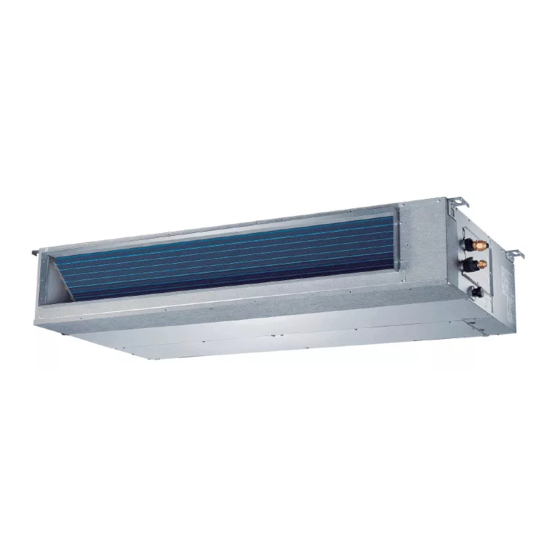
MUCR-H9
R32
Manual de instalación y usuario
Installation and owner's manual
Manuel d'installation et l'utilisauter
Benutzer- oder Installationshandbuch
Manual de instalação e do utilizador
Requisitos de información
Information requirements
Exigences en matière d'information
Informationsanforderungen
Requisitos de informação
CL20520 ~ CL20528
www.mundoclima.com
Werbung
Kapitel
Inhaltsverzeichnis
Fehlerbehebung

Verwandte Anleitungen für mundoclima MUCR-H9 18


Inhaltszusammenfassung für mundoclima MUCR-H9 18
- Seite 1 MUCR-H9 Manual de instalación y usuario Installation and owner's manual Manuel d'installation et l'utilisauter Benutzer- oder Installationshandbuch Manual de instalação e do utilizador Requisitos de información Information requirements Exigences en matière d'information Informationsanforderungen Requisitos de informação CL20520 ~ CL20528 www.mundoclima.com...
- Seite 2 Manual de instalación y usuario Installation and owner's manual Manuel d'installation et l'utilisauter Benutzer- oder Installationshandbuch Manual de instalação e do utilizador ..............................................................................................................................EU 2016/2281 Requisitos de información (para equipos > 12kW) Information requirements (for units > 12kW) Exigences en matière d'information (pour l'équipement >...
-
Seite 3: Inhaltsverzeichnis
Manual de Instalación y Usuario ÍNDICE MEDIDAS DE SEGURIDAD...………………………………………………………………………………….….4 MANUAL DE INSTALACIÓN.…………………………………………………………………………………………..8 ACCESORIOS…………………………………………………………………………………………………….…8 INSTALACIÓN DE LA UNIDAD INTERIOR………………………………………………………………9 INSTALACIÓN DE LA UNIDAD EXTERIOR……………………………………………………………19 INSTALACIÓN DE LA TUBERÍA DE REFRIGERANTE…………………………………………..…21 INSTALACIÓN DE LA TUBERIA DE DRENAJE…………………………………………….…………23 CABLEADO ELÉCTRICO………………………………………………………………………………………25 TUBERIA DE REFRIGERANTE (solo para TWIN 2x1).………………..…………………………28 PRUEBA DE FUNCIONAMIENTO.……………………………….…………..…………………………28 MANUAL DE USUARIO.……………………………….…………..……………………………………………………29 DENOMINACIÓN DE LAS PARTES…….…………..……………………………………………..……29... -
Seite 4: Medidas De Seguridad
MEDIDAS DE SEGURIDAD Gracias por adquirir este aire acondicionado. Este manual le proporcionará información sobre cómo operar, mantener y solucionar problemas de su aire acondicionado. Seguir las instrucciones asegurará el funcionamiento adecuado y la vida útil prolongada de su unidad. Lea las precauciones de seguridad antes de realizar la instalación Una instalación incorrecta debido al incumplimiento de las instrucciones puede causar daños graves o lesiones. - Seite 5 ADVERTENCIA 19. Si la entrada de alimentación está dañada, debe ser sustituida por el fabricante, su distribuidor o un técnico especializado para evitar riesgos. 20. La unidad se debe instalar teniendo en cuenta las regulaciones nacionales vigentes sobre el cableado. 21.
- Seite 6 PRECAUCIÓN En el caso de las unidades con calefactor eléctrico auxiliar, no instale la unidad a una distancia de menos de 1 m (3 pies) de cualquier material combustible. No instale la unidad en un lugar donde esté expuesto a fugas de gases combustibles. Si el gas combustible se acumula alrededor de la unidad puede provocarse un incendio.
-
Seite 7: Observaciones Sobre Los Gases Fluorados
Precauciones para el uso del refrigerante R32 3. No acelere el proceso de desescarche o la limpieza, cumpla con las recomendaciones del fabricante. 4. La unidad se debe guardar en una habitación sin fuentes de calor activa (p.ej.: llamas abiertas, una cocina de gas o un calefactor eléctrico). -
Seite 8: Manual De Instalación
MANUAL DE INSTALACIÓN ACCESORIOS Asegurarse de que estos accesorios vengan provistos con el equipo. NOMBRE ELEMENTOS CANTIDAD 1. Insonorizada /Funda aislante (en algunos modelos) Accesorios unidad interior 2. Tubo protector del cableado ... -
Seite 9: Instalación De La Unidad Interior
1. INSTALACIÓN DE LA UNIDAD INTERIOR 1.2 Instalación del cuerpo principal ø Instalación de las 4 varillas de sujeción de 10 mm Lugar de instalación Consultar las siguientes figuras para ubicar las 4 varillas de sujeción. La unidad interior debe estar instalada en un lugar que cumpla los ... - Seite 10 1.2.4 Viga de acero en el techo Instale y utilice directamente el ángulo de apoyo del acero. Varilla de sujeción Ángulo de Varilla de apoyo de sujensión acero . Colocación de la unidad interior (1) Cuelgue la unidad interior en las varillas de sujeción con el bloque. (2) Colocar la unidad interior a un nivel horizontal, usar el indicador de nivel, a menos que pueda causar fugas.
- Seite 11 Dimensiones de la unidad interior Entrada de aire posterior Filtro de aire 25 Tubo condensados (para la bomba) 4-orificios de suspensión Caja de control eléctrico Tapa de prueba y comprobación 25 Tubo condensados Líquido Entrada de aire fresco Modelo 12 90mm Entrada de aire inferior Filtro de aire...
- Seite 12 ¿Cómo ajustar el sentido de la entrada de aire? (Parte posterior (por defecto) o inferior) Extraiga el panel de ventilación y el reborde. 2. Cambie la posición del panel de ventilación y del reborde. Panel de ventilación Reborde de retorno de aire ...
- Seite 13 OPCIÓN 2: Automáticamente mediante la función "AF" del control remoto cableado AU-KJR-120G/TF-E. Pasos a seguir: 1. Asegurarse de que la bateria evaporadora de la unidad interior esta compleamente seca, sino lo esta hacer funcionar el equipo en modo VENTILACIÓN durante almenos 2 horas para secar la batería. 2.
- Seite 14 Volumen de aire constante Presión estática disponible (Pa) MUCR-18-H9 Caudal de aire (m3/h) Caudal de aire (m3/h) (sin filtro) SP1 (Ajuste 1) (sin filtro) SP2 (Ajuste 2) Presión estática disponible (Pa) Presión estática disponible (Pa) Caudal de aire (m3/h) Caudal de aire (m3/h) (sin filtro) SP3 (Ajuste 3) SP4 (Ajuste 4)
- Seite 15 Volumen de aire constante Presión estática disponible (Pa) MUCR-24-H9 Caudal de aire (m3/h) (sin filtro) 2400 SP1 (Ajuste 1) SP2 (Ajuste 2) 2200 SP3 (Ajuste 3) 2000 SP4 (Ajuste 4) 1800 1600 1400 1200 1000 SP4-H SP1-L SP1-M SP1-H SP2-L SP2-M SP2-H SP3-L SP3-M SP3-H SP4-L SP4-M...
- Seite 16 MUCR-30-H9 MUCR-36-H9 Caudal de aire (m3/h) (sin filtro) 3200 SP1 (Ajuste 1) SP2 (Ajuste 2) 3000 SP3 (Ajuste 3) 2800 SP4 (Ajuste 4) 2600 2500 2400 2200 2000 1800 1600 1400 SP4-H 1200 SP3-H SP4-L SP4-M SP1-M SP1-H SP2-L SP2-M SP2-H SP3-L SP3-M SP1-L 1000...
- Seite 17 MUCR-42-H9 MUCR-48-H9 MUCR-48-H9T Caudal de aire (m3/h) (sin filtro) SP1 (Ajuste 1) 4800 SP2 (Ajuste 2) 4400 SP3 (Ajuste 3) 4000 SP4 (Ajuste 4) 3600 3200 3100 2800 2400 SP4-H 2000 SP4-M 1600 SP4-L 1500 SP3-L SP3-M SP3-H SP1-L SP1-M SP1-H SP2-L SP2-M SP2-M...
- Seite 18 MUCR-60-H9T Caudal de aire (m3/h) (sin filtro) 4800 SP1 (Ajuste 1) 4400 SP2 (Ajuste 2) SP3 (Ajuste 3) 4000 SP4 (Ajuste 4) 3600 3200 2800 SP4-H 2400 SP4-M 2000 SP4-L 1600 SP1-L SP1-H SP2-L SP2-M SP2-H SP1-M SP3-L SP3-M SP3-H 1200 Presión estática disponible (Pa) 20 25 30...
-
Seite 19: Instalación De La Unidad Exterior
INSTALACIÓN DE LA UNIDAD EXTERIOR Dimensiones del equipo Precauciones al seleccionar la ubicación 1) Seleccione un lugar bien firme que soporte el peso y la vibración de la unidad, donde no se amplifique el ruido de funcionamiento. 2) Tenga en cuenta que la descarga de aire de la unidad o el ruido no moleste a los vecinos. -
Seite 20: Conexión Del Desagüe
2.4 Instalación de la unidad exterior 2.3 Guía de instalación ■ Instalación individual Instalación de la unidad exterior Al instalar la unidad exterior consulte "Precauciones al seleccionar la ubicación". Compruebe la solidez y la nivelación de la instalación para evitar que la unidad provoque vibraciones o ruidos después de instalada. -
Seite 21: Instalación De La Tubería De Refrigerante
Caso 2 Caso 1 INSTALACIÓN DE LA TUBERÍA DE A: Vertical REFRIGERANTE B: Total Todas las tuberías las debe suministrar un especialista en refrigeración y deben cumplir la normativa nacional correspondiente. Precauciones Aísle térmicamente ambos lados completos de las tuberías de gas y líquido. -
Seite 22: Tuberías De Refrigerante
2) Abra completamente la válvula de baja presión del puente de 5) Compruebe que el ensanchamiento está bien manómetros (baja) y cierre su válvula de alta presión (alta). realizado. El extremo de la tubería (Por tanto la válvula de alta presión no necesita manipulación). debe estar ensanchado de forma pareja en un ... -
Seite 23: Tendido De Las Tuberías
3.5 Trabajo de las tuberías de refrigerante INSTALAR LA TUBERÍA DE DRENAJE 1) Precauciones en la manipulación de los tubos 4.1 Instale las tuberías de drenaje. Proteja el extremo abierto de la tubería del polvo y Mantener la tubería lo más corta posible y tiéndala en la humedad. - Seite 24 4.3 Prueba de la tubería de desagüe Mantenimiento del motor y de la bomba de drenaje (Tome como ejemplo la unidad con retorno posterior) Compruebe si la tubería de drenaje no tiene obstáculos. Las casas de nueva construcción deben realizar esta prueba antes de ...
-
Seite 25: Cableado Eléctrico
Sección transversal nominal mínima de los cables: 5. CABLEADO ELÉCTRICO Consumo de Instrucciones generales Sección nominal corriente del Todos los cables y componentes los debe instalar un electricista equipo (A) autorizado y deben cumplirse las directivas europeas y <6 0,75 nacionales correspondientes. - Seite 26 MUCR-24/30/36/42/48-H9 MUCR-48/60-H9T UNIDAD EXTERIOR UNIDAD EXTERIOR UNIDAD INTERIOR UNIDAD INTERIOR S2 S1 S2 S1 No usar No usar 230 Vac 230 Vac 230 Vac 50 Hz 400 Vac 50 Hz 50 Hz 50 Hz Usar cable apantallado para la interconexión Usar cable apantallado para la interconexión Nota: El terminal de interconexión S1 puede denominarse P, y S2 como Q.
-
Seite 27: Conexión De Los Cables
Para más información, sobre el ajuste mediante el control remoto RG57, por favor póngase en contacto con el servicio post-venta de MUNDOCLIMA, con su comercial o visite www.mundoclima.com en el apartado correspondiente a este modelo encontrará el manual de ajuste de parámetros. -
Seite 28: Tuberia De Refrigerante (Solo Para Twin 2X1)
Dimensiones de las tuberías de la unidad exterior 6. TUBERÍA DE REFRIGERANTE (solo para Twin (2x1)) Consulte las tablas siguientes para seleccionar los diámetros de las tuberías de conexión de la unidad exterior. En caso contradicción, seleccione la más larga. 6.1 Longitud y altura permitida para la tubería de refrigerante. -
Seite 29: Manual De Usuario
MANUAL DE USUARIO DENOMINACIÓN DE LAS PARTES UNIDAD INTERIOR UNIDAD EXTERIOR Swing Timer Day off/Del Confirm Back/Turbo Copy/ Follow me Mode Fan speed (Lock) UNIDAD INTERIOR UNIDAD EXTERIOR Tubería de conexión Salida de aire Entrada de aire Entrada de aire Filtro de aire (algunos... -
Seite 30: Funciones Y Rendimiento Del Aire Acondicionado
El aire acondicionado se compone de unidad interior, exterior, la El indicador de FUNCIONAMIENTO de la unidad interior tubería de conexión y el control remoto. comenzará a parpadear cuando se restablezca el suministro de corriente. Indicadores de función en la pantalla de la unidad interior ... -
Seite 31: Limpieza Del Filtro De Aire
Mantenimiento después de un largo período Si ha configurado la unidad con retorno inferior, extraiga apagado los filtros tal como indican las siguientes flechas: (p.ej: al principio de la temporada) Compruebe si hay algún objeto que pueda estar bloqueando la entrada y salida de aire de las unidades interior y exterior. -
Seite 32: Sintomas Que Nos Son Problemas Del Aire Acondicionado
4. SÍNTOMAS QUE NO SON Síntoma 4.3: Unidad exterior PROBLEMAS DEL AIRE ACOND. Cuando cambia el tono del sonido habitual de funcionamiento. Se debe al cambio de frecuencia. Síntoma 1: El sistema no funciona Síntoma 5: Sale polvo de la unidad El aire acondicionado no se enciende inmediatamente después de Cuando la unidad se usa por primera vez en largo tiempo. -
Seite 33: Localización De Averías
5. LOCALIZACIÓN DE AVERÍAS Problemas del aire acondicionado y sus PRECAUCIÓN causas Desconecte el equipo de la corriente cuando aparezcan Si ocurre una de las siguientes averías, detenga el los fallos siguientes, compruebe si el voltaje está fuera funcionamiento del equipo, desconéctelo de la electricidad y de rango, si la instalación del aire acondicionado es póngase en contacto con su instalador autorizado. - Seite 34 Tabla 5-2 Códigos de error en el control cableado de pared (AU-KJR-120G) Nº Código Descripción Error de comunicación entre la unidad interior y el control cableado de pared Error con el panel deslizable (solo algunos cassettes) La rejilla de entrada de aire no encaja bien (solo algunos cassettes) Error en la secuencia de las fases de alimentación eléctrica Error de comunicación entre la unidad interior y la exterior Error del sensor de temperatura ambiente (T1) de la unidad interior...
- Seite 35 Tabla 5-4 Síntomas Causas Solución Fallo de corriente. Espere a que regrese el El interruptor está apagado. suministro eléctrico. El fusible del interruptor puede estar La unidad no enciende Encienda el interruptor. fundido. • Sustituya las baterías o compruebe el •...
-
Seite 36: Control Remoto Cableado
CONTROL REMOTO CABLEADO AU-KJR-120G/TF-E ● Este manual ofrece una descripción detallada de todas las precauciones que se deben tener en cuenta durante el funcionamiento. ● Para asegurar el buen funcionamiento del control remoto cableado, le rogamos lea este manual cuidadosamente antes de usar la unidad. - Seite 37 I. Medidas de seguridad Las descripciones sobre el producto en este manual, incluido el uso, son precauciones para evitar lesiones y pérdidas materiales, así como métodos del uso correcto y seguro del producto. Después de una comprensión completa de todo el contenido (identificadores e iconos), leer el texto y observar las reglas.
-
Seite 38: Accesorios De Instalación
2. Accesorios de instalación 2.1 Selección de la ubicación No instale el control en un sitio cubierto de aceite pesado, ni donde haya vapores o gases sulfurosos, de lo contrario este producto se podrá deformar y averiarse. 2.2 Preparación previa a la instalación 1. -
Seite 39: Instalación De La Batería
2. Extraer la parte superior del control cableado Con un destornillador plano desanclar las 2 pestañas de la parte inferior del control calbeado, extrar la parte superior del control (Fig. 3-2). CUIDADO La placa electrónica esta montada en la parte Pestañas superior del control cableado. - Seite 40 5. Conexión del control cableado El control dispone de 4 posibilidades de extraer los cables: 1 por la parte posterior 2 por la parte inferior 3 por la parte superior 4 por la parte superior central HA HB HA HB HA HB HA HB 1 Terminales en la Unidad Interior...
- Seite 41 4. Especificaciones Voltaje de entrada DC 5V/DC 12V -5~43 ℃(23~110 ℉) Temperatura ambiente RH40%~RH90%. Humedad relativa Especificaciones de cableado Tipo de cable Sección Longitud 0.75-1.25mm Cable apantallado (2 hilos) <50m 5. Caractersticas y funciones del control cableado Características: - Pantalla LCD - Visualización de codigos de error - Sensor de temperatura incorporado - Temporizador semanal...
- Seite 42 6. Pantalla LCD del control cableado 1 Icono modo de funcionamiento 8 Icono función turbo 2 Icono velocidad ventilador 9 Icono C° / F° 3 Icono oscilación vertical (izquierda/derecha) 10 Indicación temperatura 4 Icono oscilación horizontal (arriba/abajo) 11 Icono Bloqueo 5 Icono panel deslizable (solo para cassette) 12 Icono temperatura habitación 6 Icono unidad Maestra (A) / Esclava (B)
-
Seite 43: Ajustes Previos
8. Ajustes previos Ajusta la fecha y hora actual Timer Pulse el TEMPORIZADOR durante 2 segundos o más. El icono del temporizador parpadeará. Pulse el botón “ + ” o “ - ” para ajustar la fecha. La ... -
Seite 44: Bloqueo Para Niños
Ajuste de la velocidad del ventilador Pulse el botón FAN SPEED para ajustar la velocidad del ventilador. (Este botón no está disponible cuando el equipo está en modo automático o secado) Fan speed (Lock) Función "Follow me" (Sensor temp. ambiente en control de pared / unidad interior) Copy/ Follow me Unidad Interior... - Seite 45 Función Panel Deslizable (en algunos modelos de cassette) 1. Cuando el equipo esta en marcha (ON), mantenga pulsado el botón MODE (A/B) para activar la función Panel Deslizable. En la pantalla parpadeará el icono Mode El código F2 aparece cuando se ajusta el panel.
- Seite 46 10. Tipos de temporizadores Temporizador de Encendido (Timer On) Use esta función para activar el aire acondicionado. El A/A se enciende después de que pase el período de tiempo programado. Temporizador de Apagado (Timer Off) Use la función del temporizador para detener el A/A, se detendrá después de que pase el período de tiempo programado.
-
Seite 47: Ajuste Del Temporizador
Confirm Pulse el botón “ + ” o “ - ” para ajustar el tiempo del temporizador de encendido y luego pulse el botón CONFIRM para confirmar el ajuste. Pulse el botón “ + ” o “ - ” para ajustar el apagado del temporizador de apagado. - Seite 48 El resto de patrones del temporizador se pueden ajustar repitiende los 3 y 4 El resto de dias de la semana se pueden ajustar repitiende los del 2 al 5 NOTA: Durante el ajuste del temporizador semanal se puede volver al paso anterior pulsando el botón BACK.
- Seite 49 Pulse el botón BACK para retroceder al programador Back/Turbo semanal. Para cancelar: Siga el mismo procedimiento como para el ajuste. Nota: El ajuste de DAY OFF se cancela automáticamente después de que pase el día programado. Función retraso (DELAY) Mientras el temporizador este activo, pulsar el botón DEL una vez, se muestrará...
-
Seite 50: Códigos De Error
Confirm Pulse el botón CONFIRM otra vez para confirmar los ajustes. Pulse el botón BACK para retroceder al Back/Turbo programador semanal. 11. Códigos de error Si el sistema presenta alguna anomalía el control indicará uno de los códigos de error siguientes: error siguientes: Códigos de error en el control cableado de pared (AU-KJR-120G) Nº... -
Seite 51: Información De Servicio
INFORMACIÓN DE SERVICIO Por favor, tenga en cuenta toda la información de servicio antes de realizar cualquier tarea de instalación, mantenimiento o manipulación de este equipo de aire acondicionado con gas R-32. - Seite 52 1. Comprobaciones de la zona de trabajo Antes de comenzar el trabajo en los sistemas que contengan refrigerantes inflamables, son necesarios los controles de seguridad para asegurar que el riesgo de incendio está minimizado. Para reparar el sistema refrigerante se deben cumplir las siguientes precauciones antes de realizar los trabajos en el sistema.
- Seite 53 La cantidad de carga es según el tamaño del compartimento dentro del cual se instalan las piezas. El ventilador y las salidas están funcionando bien y no están obstruidas. Si se usa un circuito indirecto de refrigerante, el circuito secundario se debe comprobar en búsqueda de refrigerante.
- Seite 54 11. Reparación de componentes seguros No aplique ningún inductor permanente o cargas de capacitancia al circuito sin asegurar que esto no excederá el voltaje ni la corriente permisible para el equipo en uso. Estos componentes seguros son los únicos con los que se puede trabajar en una ambiente de gases inflamables. El comprobador debe tener el rango correcto.
-
Seite 55: Procedimientos De Carga
Cuando la carga OFN se usa, se debe ventilar el sistema para que baje a la presión atmosférica y de esta manera permitir que funcione. Esta operación es vital cuando se va a soldar. Asegúrese de que la salida de la bomba de vacío no está cerrada a fuentes de ignición y de que hay ventilación. - Seite 56 18. Etiquetado El equipo se debe etiquetar mencionando que está reparado y sin refrigerante. La etiqueta debe tener la fecha y la firma. Asegúrese de que hay etiquetas en el equipo con la actualización del estado del refrigerante inflamable. 19. Recuperación Se recomienda usar las buenas prácticas recomendadas cuando extraiga el refrigerante ya sea por mantenimiento o instalación.
- Seite 57 Installation and Owner's Manual CONTENT SAFETY PRECAUTIONS.………………………………………………………………………………….……………..58 INSTALLATION MANUAL. …………………………………………………………………………………………..62 ACCESSORIES…………………………………………………………………………………..……………….62 INDOOR UNIT INSTALLATION……………………………………………………………………………63 OUTDOOR UNIT INSTALLATION ………………………………………………………………….……73 INSTALL THE REFRIGERANT PIPE………………………………………………………..………….…75 CONNECT THE DRAIN PIPE…………………………………………………………….…….…………..77 ELECTRIC WIRING WORK……………………………………………………………………………….…79 REFRIGERANT PIPE (only for TWIN 2x1).………………..…………………….…………..….…82 TEST RUN.……………………………….…………..………………………………………………..…………82 OWNER’S MANUAL.……………………………….…………..……………………………………………………..…83 PART NAMES…….…………..………………………………………………………………………..……83 AIR CONDITIONER OPERATIONS AND PERFORMANCE…….…………..……..………..
-
Seite 58: Safety Precautions
SAFETY PRECAUTIONS Thank you for purchasing this air conditioner. This manual will provide you with information on how to operate, maintain, and troubleshoot your air conditioner. Following the instructions will ensure the proper function and extended lifespan of your unit. Read Safety Precautions Before Installation Incorrect installation due to ignoring instructions can cause serious damage or injury. -
Seite 59: Electrical Warnings
WARNING 19. If the supply cord is damaged, it must be replaced by the manufacturer,its service agent or similarly qualified persons in order to avoid a hazard. 20. The appliance shall be installed in accordance with national wiring regulations. 21. An all-pole disconnection device which has at least 3mm clearances in all poles, and have a leakage current that may exceed 10mA,the residual current device (RCD) having a rated residual operating current not exceeding 30mA,and disconnection must be incorporated in the fixed wiring in accordance with the wiring rules. - Seite 60 CAUTION For units that have an auxiliary electric heater, do not install the unit within 1 meter (3 feet) of any combustible materials. Do not install the unit in a location that may be exposed to combustible gas leaks. If combustible gas accumulates around the unit, it may cause fire.
- Seite 61 Cautions for using R32 refrigerant 3. Do not use means to accelerate the defrosting process or to clean, other than those recommended by the manufacturer. 4. The appliance shall be stored in a room without continuously operating ignition sources (for example: open flames,an operating gas appliance or an operating electric heater) 5.
-
Seite 62: Installation Manual
INSTALLATION MANUAL ACCESSORIES Please check whether the following fittings are of full scope. If there are some spare fittings , please restore them carefully. NAME SHAPE QUANTITY 1. Soundproof / insulation sheath (some models) Tubing & Fittings 2. Outlet pipe sheath (some models) 3. -
Seite 63: Indoor Unit Installation
INDOOR UNIT INSTALLATION 1.2 Install the main body Installing 10 hanging screw bolts. (4 bolts) Installation place Please refer to the following figures for positioning 4 screw bolts. The indoor unit should be installed in a location that meets the Evaluate the ceiling construction and please install with following requirements: hanging screw bolts. - Seite 64 1.2.4 Steel roof beam structure Install and use directly the supporting angle steel. Hanging screw bolt Supporting Hanging bolts angle steel Overhanging the indoor unit (1) Overhang the indoor unit onto the hanging screw bolts with block. (2) Position the indoor unit in a flat level by using the level indicator, unless it may cause leakage.
- Seite 65 The positioning of ceiling hole, indoor unit and hanging screw bolts Air inlet from rear side Air filter 25 Drain connecting pipe (for pump) 4-install hanger Electric control box Test mouth and Test cover 25 drain pipe Gas side Liquid side Fresh air intake Model 12 90mm...
- Seite 66 How to adjust the air inlet direction? (From rear side to under-side) 1. Take o the ventilation panel and ange. 2. Change the mounting positions of the ventilation panel and air return ange. Air return ange Ventilation panel Ventilation panel Air return ange 3.
- Seite 67 OPTION 2: Automatically using the "AF" function of the AU-KJR-120G / TF-E in the wired remote control. Please, follow the steps: 1. Make sure that the evaporator battery of the indoor unit is completely dry. If it isn’t turn on the equipment in VENTILATION mode for at least 2 hours to dry the battery.
- Seite 68 External static pressure (Pa) MUCR-18-H9 Air flow (m3/h) Air flow (m3/h) (without filter) SP1 (Setting 1) (without filter) SP2 (Setting 2) External static pressure (Pa) External static pressure (Pa) Air flow (m3/h) Air flow (m3/h) (without filter) SP4 (Setting 4) SP3 (Setting 3) (without filter) External static pressure (Pa)
- Seite 69 Constant air volume External static pressure (Pa) MUCR-24-H9 Air flow (m3/h) (without filter) 2400 SP1 (Setting 1) SP2 (Setting 2) 2200 SP3 (Setting 3) 2000 SP4 (Setting 4) 1800 1600 1400 1200 1000 SP4-H SP1-L SP1-M SP1-H SP2-L SP2-M SP2-H SP3-L SP3-M SP3-H SP4-L SP4-M 20 25 30...
- Seite 70 MUCR-30-H9 MUCR-36-H9 Air flow (m3/h) (without filter) SP1 (Setting 1) 3200 SP2 (Setting 2) 3000 SP3 (Setting 3) 2800 SP4 (Setting 4) 2600 2500 2400 2200 2000 1800 1600 1400 SP4-H 1200 SP3-H SP4-L SP3-L SP3-M SP4-M SP1-M SP1-H SP2-L SP2-M SP2-H SP1-L 1000 External static pressure (Pa)
- Seite 71 MUCR-42-H9 MUCR-48-H9 MUCR-48-H9T Air flow (m3/h) (without filter) SP1 (Setting 1) 4800 SP2 (Setting 2) 4400 SP3 (Setting 3) 4000 SP4 (Setting 4) 3600 3200 3100 2800 2400 SP4-H 2000 SP4-M 1600 SP4-L 1500 SP1-H SP3-L SP3-M SP3-H SP1-L SP1-M SP2-L SP2-M SP2-M 1200...
- Seite 72 MUCR-60-H9T Air flow (m3/h) (without filter) 4800 SP1 (Setting 1) 4400 SP2 (Setting 2) SP3 (Setting 3) 4000 SP4 (Setting 4) 3600 3200 2800 SP4-H 2400 SP4-M 2000 SP4-L 1600 SP1-L SP1-H SP2-L SP2-M SP2-H SP1-M SP3-L SP3-M SP3-H 1200 20 25 30 40 50 60 70 80 90 100 110 120 130 140 150 160...
-
Seite 73: Outdoor Unit Installation
OUTDOOR UNIT INSTALLATION Figure of body size Precautions for selecting the location 1) Choose a place solid enough to bear the weight and vibration of the unit, where the operation noise will not be amplified. 2) Choose a location where the hot air discharged from the unit or the operation noise will not cause a nuisance to the neighbours of the user. -
Seite 74: Drain Work
2.4 Outdoor unit installation 2.3 Installation guidelines Individual installation 1) Installing outdoor unit When installing the outdoor unit, refer to "Precautions for selecting the location" . Check the strength and level of the installation ground so that the unit will not cause any operating vibration or noise after installed. -
Seite 75: Install The Refrigerant Pipe
Case 2 INSTALL THE REFRIGERANT PIPE Case 1 A: Vertical B: Total All field piping must be provided by a licensed refrigeration technician and must comply with the relevant local and national codes. Precautions Execute heat insulation work completely on both sides of the gas piping and liquid piping. -
Seite 76: Refrigerant Piping
1) Connect projection side of charging hose (which comes from 5) Check that the flaring is properly made. gauge manifold) to gas stop valve's service port. The pipe end must 2) Full open gauge manifold's low-pressure valve (Lo) and be evenly flared in a perfect circle. -
Seite 77: Connect The Drain Pipe
3.5 Refrigerant pipig work CONNECT THE DRAIN PIPE 1) Caution on the pipe handling 4.1 Install the drain pipes. Protect the open end of the pipe against dust and moisture. Keep piping as short as possible and slope it downwards at a All pipe bends should be as gentle as possible. - Seite 78 Motor and drain pump maintenance 4.3 Testing of drain piping (Take rear ventilated as example) Check whether the drainpipe is unhindered. Motor maintain: New built house should have this test done before paving the ceiling. 1. Take off the ventilated panel. The unit with pump.
-
Seite 79: Electric Wiring Work
ELECTRIC WIRING WORK Minimum nominal cross-sectional area of conductors: General instructions Rated current Nominal cross-sectional of appliance area All field wiring and components must be installed by a licensed (mm2) electrician and must comply with relevant European and national <6 0.75 regulations. - Seite 80 MUCR-24/30/36/42/48-H9 MUCR-48/60-H9T OUTDOOR UNIT OUTDOOR UNIT INDOOR UNIT INDOOR UNIT S2 S1 S2 S1 No use No use 230 Vac 230 Vac 230 Vac 50 Hz 400 Vac 50 Hz 50 Hz 50 Hz Use shielded cable for interconnection Use shielded cable for interconnection Note: Interconnection terminal S1 can be called P, and S2 as Q.
- Seite 81 The capacity of the unit, the address of the unit, temperature compensation, etc. it can be setting by remote control RG57 or by indoor dip-switch. For more information, please contact the after-sales service Mundoclima, with your sales man or visit www.mundoclima.com in the corresponding model section you will find the parameters setting manual.
-
Seite 82: Refrigerant Pipe (Only For Twin 2X1)
REFRIGERANT PIPE 6.3 Size of joint pipes for outdoor unit (the unit with the twins function) Base on the following tables, select the diameters of the outdoor unit connective pipes. In case of the main accessory pipe large than the main pipe, take the large one for the selection. 6.1 Length and drop height permitted of the refrigerant piping Size of joint pipes for outdoor unit Note: Reduced length of the branching tube is the 0.5m of the... -
Seite 83: Owner's Manual
OWNER'S MANUAL PARTS NAMES INDOOR UNIT OUTDOOR UNIT Swing Timer Day off/Del Confirm Back/Turbo Copy/ Follow me Mode Fan speed (Lock) INDOOR UNIT OUTDOOR UNIT Connecting pipe Air outlet Air inlet Air inlet Air filter (on some models) Air inlet (side and rear) Electric control cabinet Air outlet Wire controller... -
Seite 84: Air Conditioner Operations And Performance
Power failure The air conditioner consists of the indoor unit, the outdoor unit, the connecting pipe and the remote controller. Power failure during operation will stop the unit completely. Function indicators on indoor unit display panel The OPERATION lamp on the indoor unit will start flashing when power is restored. -
Seite 85: Maintenance After A Long Stop Period
Maintenance after a long stop period If the unit you purchased is a descensional ventilated one, take off the filter in the directions indicated by arrows in the following digram. (eg. at the beginning of the season) Check and remove everything that might be blocking inlet and outlet vents of indoor units and outdoor units. -
Seite 86: Following Symptoms Are Not Air Conditioner Troubles
4. FOLLOWING SYMPTOMS ARE NOT Symptom 4.3: Outdoor unit AIR CONDITIONER TROUBLES When the tone of operating noise changes. This noise is caused by the change of frequency. Symptom 1: The system does not operate Symptom 5: Dust comes out of the unit The air conditioner does not start immediately after the ON/OFF button on the romote controller is pressed. -
Seite 87: Troubleshooting
5. TROUBLESHOOTING 5.1. T roubles and causes of air conditioner CAUTION If one of the following malfunctions occur, stop operation, shut Please cut off the power supply when appearing the off the power, and contact with your dealer. above malfunction, check if the voltage provided is out of The operation lamp is flashing rapidly (5Hz). - Seite 88 Table 5-2 Wired controller error codes Nº Code Description Error of communication between wire controller and indoor unit The lifting filter function is abnormal The air inlet grill doesn't fit well of Super slim four-way cassette Error of power supply phase sequence Error of communication between indoor unit and outdoor unit T1 temp. sensor is abnormal T2A temp. sensor is abnormal T2B temp. sensor is abnormal T3/T4 temp. sensor is abnormal or compressor discharge temp. sensor is abnormal Zero crossing detection error EEPROM malfunction Fan speed out of control The communication between main board and the display board is abnormal EA Compressor over current protection (four times) EB IPM malfunction ED Outdoor unit malfunction Water-level alarm and other malfunction Other malfunction Table 5-3 Outdoor unit error codes (Models 24 to 60). Nº...
- Seite 89 Table 5-4 Symptoms Causes Solution Power failure. Wait for the comeback of power. Power switch is off. Switch on the power. Fuse of power switch may have burned. ReplLocation: Unit does not start Batteries of remote controller exhausted Replace the batterises or check the or other problem of controller.
-
Seite 90: Wired Controller
WIRED CONTROLLER AU-KJR-120G/TF-E ● This manual gives detailed description of the precautions that should be brought to your attention during operation. ● In order to ensure correct service of the wired controller please read this manual carefully before using the unit. ●... - Seite 91 I. Safety precautions The following contents are stated on the product and the operation manual, including usage, precautions against personal harm and property loss, and the methods of using the product correctly and safely. After fully understanding the following contents (identifiers and icons), read the text body and observe the following rules.
-
Seite 92: Installation Method
2. Installation accessory 2.1 Select the installation location Don’t install at the place where cover with heavy oil, vapor or sulfureted gas, otherwise, this product would be deformed that would lead to system malfunction. 2.2 Preparation before installation 1. Please confirm that all the following parts you have been supply. Name Qty. -
Seite 93: Battery Installation
2. Remove the upper part of wire controller Insert a slot screwdriver into the slots in the lower part of the wire controller (2 places), and remove the upper part of the wire controller. (Fig.3-2) NOTICE The PCB is mounted in the upper part of the wire Slots controller. - Seite 94 5. Wire the indoor unit 4 methods 1 from the rear; 2 from the bottom; 3 from the top; 4 from the top center. HA HB HA HB HA HB HA HB 1 indoor unit 2 notch the part for the wiring to pass through with nippers, etc. Connect the terminals on the remote controller (HA ,HB), and the terminals of the indoor unit (HA ,HB).
- Seite 95 4. Specification DC 5V/DC 12V Input voltage Ambient temperature -5~43℃(23~110℉) RH40%~RH90% Ambient humidity Wiring specifications Wiring type Total length Size Shielded vinyl cord or cable 0.75-1.25mm <50m 5. Feature and function of the wired controller Feature: LCD display. Malfunction code display: it can display the error code, helpful for service.
- Seite 96 6. Name on the LCD of the wire controler 1 Operation mode indication 8 Turbo function indication 2 Fan speed indication 9 C° / F° indication 3 Left-right swing indication 10 Temperature display 4 Up-down swing indication 11 Lock indication 5 Faceplate function indication 12 Room temperature indication 6 Main unit and secondary unit indication...
- Seite 97 8. Preparatory operation Set the current day and time Timer Press the TIMER button for 3 seconds or more. The timer display will flash. Press the button “ + ” or “ - ” to set the date. The selected date will flash.
- Seite 98 Fan speed setting Press the FAN SPEED button to set the fan speed. (This button is unavailable when in the mode of Auto or Dry) Fan speed (Lock) Room temperature sensor selection Copy/ Follow me Indoor Unit Press the Follow me button to select whether the room temperature is detected at the indoor unit or the wire controller.
- Seite 99 Faceplate function (on some models) 1.When the unit is off, Press the Mode(A/B) button long to activate the faceplate function. The mark will flash. Mode The F2 mark appears when the faceplate is adjusted. 2. Push the Mode(A/B) button to select Unit A or Unit B, the wire controller select in a sequence that goes from (this step do not need to perform if the wire controller is connected with one unit only): 3.
-
Seite 100: Timer Functions
10. Timer functions On timer Use this timer function to start air conditioner operation.The timer operates and air conditioner operation starts after the time has passed. Off timer Use this timer function to stop air conditioner operation.The timer operates and air conditioner operation stops after the time has passed. On and Off timer Use this timer function to start and stop air conditioner operation.The timer operates and air conditioner operation starts and stops after the time has... -
Seite 101: Weekly Timer
To set the On and Off TIMER Timer Press the TIMER button to select the Confirm Press the CONFIRM button and the Clock display is flashing. Confirm Press the button “ + ” or “ - ” to set the time of On timer, and then press the CONFIRM button to confirm the setting. -
Seite 102: Time Setting
Time setting Confirm Press the button “ + ” and “ - ” to set the time.and then press the Confirm button to confirm the setting. Different time scales can be setted by repeating step 3 and 4. Other days in one week can be setted by repeating step 2 to 5. NOTE: The weekly timer setting can be returned to the previous step by pressing Back button. -
Seite 103: Delay Function
Press the Day off button to set the DAY OFF. Day off/Del mark is hidden ex.The DAY OFF is set for Wednesday The DAY OFF can be setted for other days by repeating the steps 2 and 3. Back/Turbo Press the Back button to back to the weekly timer. To cancel:Follow the same procedures as those for setup。... - Seite 104 Press the Copy button to confirm . Copy/ Follow me mark flashes quickly ex. Copy the setting of Monday to Wednesday Other days can be copied by repeating step 4 and 5. Press the Confirm button to confirm the settings. Confirm Press the Back button to back to the weekly timer.
-
Seite 105: Information Servicing
INFORMATION SERVICING Please note all service information before performing any installation, maintenance or handling of this R-32 gas air conditioner. - Seite 106 1. Checks to the area Prior to beginning work on systems containing flammable refrigerants, safety checks are necessary to ensure that the risk of ignition is minimised. For repair to the refrigerating system, the following precautions shall be complied with prior to conducting work on the system. 2.
- Seite 107 the charge size is in accordance with the room size within which the refrigerant containing parts are installed; the ventilation machinery and outlets are operating adequately and are not obstructed; if an indirect refrigerating circuit is being used, the secondary circuits shall be checked for the presence of refrigerant;...
-
Seite 108: Removal And Evacuation
11. Repair to intrinsically safe components Do not apply any permanent inductive or capacitance loads to the circuit without ensuring that this will not exceed the permissible voltage and current permitted for the equipment in use. Intrinscially safe components are the only types that can be worked on while live in the presence of a flammable atmosphere. -
Seite 109: Charging Procedures
When the final OFN charge is used, the system shall be vented down to atmospheric pressure to enable work to take place. This operation is absolutely vital if brazing operations on the pipe-work are to take place. Ensure that the outlet for the vacuum pump is not closed to any ignition sources and there is ventilation available. - Seite 110 18. Labelling Equipment shall be labelled stating that it has been de-commissioned and emptied of refrigerant. The label shall be dated and signed. Ensure that there are labels on the equipment stating the equipment contains flammable refrigerant. 19. Recovery When removing refrigerant from a system, either for service or decommissioning, it is recommended good practice that all refrigerants are removed safely.
- Seite 111 Manuel d'installation et d'utilisation INDEX MESURES DE SÉCURITÉ...……………………………………..…………………………………………………….112 MANUEL D’INSTALLATION.…………………………………………………………………….………………..116 ACCESSOIRES………………………………………………………………………………………….………116 INSTALLATION DE L’UNITÉ INTÉRIEURE ………………………………………………………...117 INSTALLATION DE L’UNITÉ EXTÉRIEURE …………………………………………………….…..127 INSTALLATION DU TUYAU DU RÉFRIGÉRANT…….……………………………………….…..129 INSTALLATION DU TUYAU D’ÉCOULAMENT………………………………………….…..……131 CONNEXIÓN ÉLECTRIQUE…………………………………………………………………………….…133 TUYAU DU RÉFRIGÉRANT (seulement pour TWIN 2x1).………………..…….……….…136 TEST DE FONCTIONNEMENT….………………………………...…………..…………………….…136 MANUEL DE L’ÚTILISATEUR……………………….…………..…………………………………………….….…137 NOMS DES COMPOSANTS………..…….…………..……………………………………….…….….137...
-
Seite 112: Mesures De Sécurité
MESURES DE SÉCURITÉ Merci d'avoir acheté ce climatiseur. Ce manuel vous fournira des renseignements sur la façon d'utiliser, entretenir et résoudre votre problème avec le climatiseur. Suivez les instructions qui vous assurera un bon fonctionnement et la longue durée de vie de votre appareil. Lisez les consignes de sécurité... - Seite 113 AVERTISSEMENT 19. Si l'entrée de l'alimentation est endommagée, elle doit être remplacée par le fabricant, le distributeur ou un technicien spécialisé pour éviter les risques. 20. L'unité doit s'installer en prenant compte des régulations nationales mises en vigueur sur le câblage. 21.
- Seite 114 PRÉCAUTION Pour les appareils équipés d'un chauffage électrique auxiliaire, ne pas installer l'appareil à moins de 1 m (3 pi) de tout matériau combustible. Ne pas installer l'appareil dans un endroit dangereux où il est exposé à des fuites de gaz inflammables.
-
Seite 115: Observations Sur Les Gaz Fluorés
Précautions d'emploi de réfrigérant R32 3. N'accélérez pas le processus de dégivrage ou de nettoyage, conformément aux recommandations du fabricant. 4. L’appareil doit être dans une pièce sans sources de chaleur (Ex : flammes nues, gazinière ou un chauffage électrique). 5. -
Seite 116: Manuel D'installation
MANUEL D'INSTALLATION ACCESSOIRES Assurez-vous que les accessoires soient fournis avec l'équipement. QUANTITÉ ÉLÉMENTS 1. Hausse isolante insonorisée (sur certains modèles) Tuyauterie et accessoires 2. Tube de protection de câblage (sur certains modèles) ... -
Seite 117: Installation De L'unité Intérieure
1. INSTALLATION DE L'UNITÉ INTÉRIEURE 1.2 Installation du corps principal Installation des 4 tiges de fixation de ø 10 mm Emplacement de montage Consultez les illustrations suivantes pour installer les 4 tiges de fixation. L'unité intérieure doit être installée dans un emplacement qui respecte les exigences suivantes: Évaluez la construction du plafond et installez les tiges - Il y a suffisamment d'espace pour l'installation et la... - Seite 118 1.2.4 Poutre d'acier dans le plafond Installez et utilisez directement l'angle de support en acier. Tige de fixation Angle Tige de fixation support en acier 2. Positionnement de l'unité intérieure (1) Accrochez l'unité intérieure dans les tiges de fixation avec le bloc. (2) Placer l'unité...
- Seite 119 Emplacement des trous dans le plafond, unité intérieure et tiges de fixation. Entrée d'air arrière Filtre d’air 25 Tuyau de condensat (pour pompe) 4-Trous de suspension Boîte du contrôle électrique Couvercle d'essai et de contrôle 25 Tuyau condensats Liquide Modèle 12 Entrée d’air inférieure 90mm...
- Seite 120 Comment régler la direction de l'entrée d'air? (Partie postérieure inférieure) Retirez le panneau de ventilation et le rebord. 2. Changez la position du panneau de ventilation et le rebord. Panneau de ventilation Rebord de retour d'air Rebord de retour d'air Panneau de ventilation ...
- Seite 121 OPTION 2: Automatiquement par la fonction "AF" de la télécommande câblée AU-KJR-120G / TF-E. Pas à suivre: 1. Assurez-vous que la batterie évaporatrice de l'unité intérieure soit complètement sèche, mais que l'équipement fonctionne en mode VENTILATION pendant au moins 2 heures pour sécher la batterie. 2.
- Seite 122 Pression statique externe (Pa) MUCR-18-H9 Débit d'air (m3/h) Débit d'air (m3/h) (sans filtre) SP1 (Réglage 1) (sans filtre) SP2 (Réglage 2) Pression statique externe (Pa Pression statique externe (Pa Débit d'air (m3/h) Débit d'air (m3/h) (sans filtre) (sans filtre) SP3 (Réglage 3) SP4 (Réglage 4) Pression statique externe (Pa Pression statique externe (Pa...
- Seite 123 Pression statique externe (Pa MUCR-24-H9 Débit d'air (m3/h) (sans filtre) SP1 (Réglage 1) 2400 SP2 (Réglage 2) 2200 SP3 (Réglage 3) 2000 SP4 (Réglage 4) 1800 1600 1400 1200 1000 SP4-H SP1-L SP1-M SP1-H SP2-L SP2-M SP2-H SP3-L SP3-M SP3-H SP4-L SP4-M Pression statique externe (Pa) 20 25 30...
- Seite 124 MUCR-30-H9 MUCR-36-H9 Débit d'air (m3/h) (sans filtre) 3200 SP1 (Réglage 1) SP2 (Réglage 2) 3000 SP3 (Réglage 3) 2800 SP4 (Réglage 4) 2600 2500 2400 2200 2000 1800 1600 1400 SP4-H 1200 SP3-H SP4-L SP3-L SP3-M SP4-M SP1-M SP1-H SP2-L SP2-M SP2-H SP1-L 1000 Pression statique externe (Pa)
- Seite 125 MUCR-42-H9 MUCR-48-H9 MUCR-48-H9T Débit d'air (m3/h) (sans filtre) 4800 SP1 (Réglage 1) SP2 (Réglage 2) 4400 SP3 (Réglage 3) 4000 SP4 (Réglage 4) 3600 3200 3100 2800 2400 SP4-H 2000 SP4-M 1600 SP4-L 1500 SP1-L SP1-M SP1-H SP2-M SP2-M SP3-L SP3-M SP3-H SP2-L 1200 Pression statique externe (Pa)
- Seite 126 MUCR-60-H9T Débit d'air (m3/h) (sans filtre) 4800 SP1 (Réglage 1) SP2 (Réglage 2) 4400 SP3 (Réglage 3) 4000 SP4 (Réglage 4) 3600 3200 2800 SP4-H 2400 SP4-M 2000 SP4-L 1600 SP2-H SP1-L SP1-H SP2-L SP2-M SP1-M SP3-L SP3-M SP3-H 1200 Pression statique externe (Pa 20 25 30 40 50 60...
-
Seite 127: Installation De L'unité Extérieure
INSTALLATION DE L'UNITÉ EXTÉRIEURE Dimensions de l'équipement Précautions pour le choix de l'emplacement 1) Sélectionnez un endroit bien ferme pour supporter le poids et les vibrations de l'appareil, où le bruit pendant le fonctionnement ne peut s'amplifier. - Seite 128 2.3 Guide d'installation 2.4 Installation de l'unité extérieure ■ Installation individuelle 1) Installation de l'unité extérieure Après avoir installé l'unité extérieure consultez la partie "Précautions pour sélectionner l'emplacement". Vérifiez la solidité et le nivellement de l'installation pour éviter que l'unité provoque des vibrations ou des bruits une fois installée.
-
Seite 129: Installation Du Tuyau Du Réfrigérant
Cas 2 Cas 1 INSTALLATION DU TUYAU A: Vertical RÉFRIGÉRANT B: Totale Un spécialiste en réfrigération doit fournir toutes les tuyauteries et il doit respecter la réglementation nationale correspondante. Précautions Isolez thermiquement les deux côtés complets des tuyauteries de gaz et de liquides. Sinon des égouttements d'eaux pourraient se provoquer occasionnellement. - Seite 130 1) Connectez le tube de basse pression du kit de manomètres à l'obus de vérification de pression. 5) Vérifiez que l'élargissement est bien réalisé. L'extrémité du tuyau 2) Ouvrez complètement la vanne de basse pression du kit de doit être élargie en manomètres et fermez sa vanne de haute pression.
-
Seite 131: Connexion De La Tuyauterie De Réfrigérant
INSTALLATION DU TUYAU D’ÉCOULEMENT 3.5 Connexion de la tuyauterie de réfrigérant 1) Précautions dans la manipulation des tubes 4.1 Installez les tuyauteries de drainage Maintenir la tuyauterie la plus courte possible et tendez-la Protégez l'extrémité ouverte de la tuyauterie de la dans une boucle d'oreille descendante avec une inclination poussière et de l'humidité. - Seite 132 4.3 Vérification de la tuyauterie d'écoulement Entretien du moteur et de la pompe de drainage (Prenez comme exemple l'unité avec un retour postérieur) Vérifiez si le tuyauterie d'écoulement n'a pas d'obstacles. Les maisons nouvellement construites doivent réaliser cette Entretien du moteur: vérification avant de terminer le plafond.
-
Seite 133: Câblage Électrique
Section transversale nominale minimale des câbles : 5. CÂBLAGE ÉLECTRIQUE Introductions générales Consommation Section de courant de nominale Un technicien qualifié doit installer tous les câbles et l'équipe (A) composants et ces derniers doivent être aux normes européennes et nationales correspondantes. <6 0,75 et <10... - Seite 134 MUCR-24/30/36/42/48-H9 MUCR-48/60-H9T UNITÉ EXT ÉRIEURE UNITÉ INTÉRIEURE UNITÉ EXT ÉRIEURE UNITÉ INTÉRIEURE S2 S1 S2 S1 Ne pas Ne pas utiliser 230 Vac 230 Vac 230 Vac utiliser 50 Hz 400 Vac 50 Hz 50 Hz 50 Hz Utiliser un câble blindé pour l'interconnexion Utiliser un câble blindé...
-
Seite 135: Connexion Des Câbles
Pour plus d'informations sur la configuration de la télécommande RG57, s'il vous plaît contactez le service après-vente Mundoclima avec votre agent commercial ou visiter www.mundoclima.com dans la section correspondante de ce modèle pour trouver le réglage manuel des paramètres. -
Seite 136: Tuyau Du Réfrigérant (Seulement Pour Twin 2X1)
Dimensions de tuyauterie de l'unité extérieure 6. TUYAU DU RÉFRIGÉRANT Voir les tableaux suivants pour la sélection des diamètres des (seulement pour Twin (2x1)). tuyaux de connexion de l'unité extérieure. En cas de problèmes, sélectionnez la plus longue. 6.1 Longueur et hauteur autorisées pour le tube de réfrigérant. Dimensions de la tuyauterie de l'unité... -
Seite 137: Manuel De L'útilisateur
MANUEL DE L'UTILISATEUR NOMS DES COMPOSANTS UNITÉ INTÉRIEURE UNITÉ EXTÉRIEURE Copy/ Swing Timer Day off/Del Confirm Back/Turbo Follow me Mode Fan speed (Lock) Illustr.1 UNITÉ INTÉRIEURE UNITÉ EXTÉRIEURE Tuyau de connexion Sortie d’air Entrée d'air Entrée d'air Entrée d'air (latérale et arrière) Filtre d'air (sur certains modèles) Sortie d’air... -
Seite 138: Fonctionnement Économique
Le climatiseur comprend une unité intérieure, une extérieure, un 2. FONCTIONNEMENT ÉCONOMIQUE tuyau de connexion et une télécommande Indicateurs de fonctions sur l'écran de l'unité intérieure Il faut tenir compte des aspects suivants pour assurer un Bouton manuel fonctionnement économique. (Pour plus de détails voir les Indicateur PRE-DEF chapitres correspondants). -
Seite 139: Maintenance Après Une Longue Période D'arrêt
Maintenance après une longue période Si l'unité a été configurée avec la ventilation inférieure, tirez légèrement du filtre jusqu'en bas pour le sortir de la rétention et d'arrêt sortir le filtre comme l'indiquent les flèches dans l'illustration. (p.ex: au début de la saison) Vérifiez tous les objets qui bloquent l'entrée d'air et la sortie des unités intérieures et extérieures. -
Seite 140: Les Réactions Suivantes Ne Sont Pas Des
4. LES RÉACTIONS Réaction 4.3: Unité extérieure SUIVANTES NE SONT PAS DES Lorsque le bruit du son habituel de fonctionnement change Cela est due à la variation de fréquence. PROBLÉMES VENANT DE L'AIR Réaction 5: L'unité émet de la poussière CONDITIONNÉ... -
Seite 141: Localisation De Pannes
5. LOCALISATION DE PANNES Problèmes de l'air conditionné et ses PRÉCAUTION causes Déconnectez l'équipement lorsque les défauts suivants arrêtez Si un des problèmes suivants venait à apparaitre, se produisent, vérifiez si le voltage est trop haut, si l'équipement, déconnectez-le et contactez votre installateur l'installation de l'air conditionné... - Seite 142 Tableaux 5-2 Code d'erreur de l'unité extérieure (Modèles 24 à 60) Nº Code Description 1 E1 Erreur de communication entre l'unité intérieure et l'extérieure 2 F0 Protection contre une surcharge de courant 3 F1 Erreur du capteur de température ambiante (T4) de l'unité extérieure 4 F2 Erreur du capteur de température de tuyauterie (T3) de l'unité extérieure 5 F3 Erreur du capteur de température de décharge (T5) de l'unité extérieure 6 F4 Erreur dans l'EEPROM de l'unité extérieure 7 F5 Erreur du moteur ventilateur de l'unité extérieure 8 P0 Protection du module inverter (IPM) 9 ...
- Seite 143 5.2. Problèmes de la télécommande et ses causes Avant de contacter le service technique, veuillez consulter les informations ci-dessous. (Consultez le tableau 5-4) Tableau 5-4 Réaction Solutions Causes Vérifiez si le mode indiqué Lorsque le mode automatique est sélectionné, la climatisation à...
-
Seite 144: Télécomande Câblée
TÉLÉCOMMANDE CÂBLÉE AU-KJR-120G/TF-E ● Ce manuel donne une description détaillée de toutes les précautions à prendre en compte pendant le fonctionnement de l’appareil. ● Pour assurer le bon fonctionnement de la commande murale, nous vous conseillons de lire attentivement ce manuel avant d'utiliser l'appareil. - Seite 145 I. Mesures de sécurité Ce manuel décrit les précautions à prendre afin d'éviter des blessures et des pertes matérielles, ainsi que les méthodes à adopter pour une utilisation correcte et sûre de l'appareil. Après une compréhension complète du contenu (symboles et icônes), lisez le texte et observez les règles.
-
Seite 146: Accessoires Pour L'installation
2. Accessoires pour l'installation 2.1 Choix de l'emplacement N'installez pas le produit dans un endroit couvert de mazout, ni dans un endroit exposé à des vapeurs ou à des gaz sulfureux. Le produit pourrait être endommagé et tomber en panne. 2.2 Préparation préalable à... -
Seite 147: Installation De La Batterie
2. Extraire la partie supérieure de la commande murale Insérez un tournevis plat dans les deux encoches de la partie inférieure de la commande murale pour la retirer. (Fig. 3-2). ATTENTION La plaque électrique est installée dans la Encoches partie supérieure de la commande murale. Veillez à... - Seite 148 5. Connexion de la commande murale Il existe 4 façons de retirer les câbles de la commande murale : 1 par la partie arrière 2 par la partie inférieure 3 par la partie supérieure 4 par la partie supérieure centrale HA HB HA HB HA HB...
- Seite 149 4. Spécifications Tension d'entrée: DC 5V/DC 12V -5~43 ℃(23~110 ℉) Température ambiante HR40%~HR90%. Humidité relative Spécifications du câblage Type de câble Section Longueur Câble blindé (2 fils) 0,75-1,25 mm <50 m 5. Caractéristiques et fonctions de la commande murale Caractéristiques : - Écran LCD - Visualisation des codes d’erreur - Capteur de température intégré...
- Seite 150 6. Écran LCD de la commande murale 1 Icône mode de fonctionnement 8 Icône fonction turbo 9 Icône Cº / Fº 2 Icône vitesse du ventilateur 10 Indication température 3 Icône oscillation verticale (gauche/droite) 11 Icône verouillage 4 Icône oscillation horizontale (haut/bas) 12 Icône température ambiante 5 Icône panneau coulissant (seulement 13 Indication heure...
-
Seite 151: Réglages Préalables
8. Réglages préalables Réglage de la date et de l'heure actuelle Timer Appuyez sur la touche TIMER pendant au moins 2 sec. L'icône du programmateur clignotera. Appuyez sur la touche “ + ” ou “ - ” pour régler la date. - Seite 152 Réglage de la vitesse du ventilateur Appuyez sur la touche FAN SPEED pour sélectionner la vitesse du ventilateur. (Cette touche n'est pas utilisable lorsque l'appareil est en mode automatique ou en mode séchage) speed (Lock) Fonction "Follow me" (Capteur temp. ambiante au contrôle au mur ou unité intérieure) Copy/ Follow me Unité...
- Seite 153 Fonction Panneau Coulissant (sur certains modèles Cassette) 1. Lorsque l'appareil est en marche (ON), maintenez la touche MODE (A/B) enfoncée pour activer la fonction Panneau Coulissant. L'icône clignotera à l'écran. Mode Le code F2 apparait lorsque vous réglez le panneau. 2.
- Seite 154 10. Types de programmateurs Programmateur de mise en marche (Time On) Utilisez cette fonction pour activer la climatisation. L'A/C se mettra en marche lorsque le laps de temps programmé sera écoulé. Programmateur d'arrêt (Time Off) Utilisez la fonction du programmateur pour arrêter l'A/C. Il s'éteindra lorque le laps de temps programmé...
- Seite 155 Réglage du programmateur de mise en marche ou d'arrê t (Timer ON ou Timer OFF) Timer Appuyez sur la touche TIMER pour sélectionner Appuyez sur la touche CONFIRM et l'icône de l'heure clignotera. Confirm Confirm Appuyez sur la touche “ + ” ou “ - ” pour régler l'heure de mise en marche du programmateur, puis appuyez sur la touche CONFIRM pour confirmer le réglage.
- Seite 156 Par.ex.: Mardi - Modèle 1 Vous pouvez régler jusqu'à 4 modèles pour chaque jour. Réglage du programmateur d'arrêt du modèle 1 Appuyez sur la touche “ + ” ou “ - ” pour sélectionner Confirm l´heure d'arrêt, puis appuyez sur CONFIRM pour confirmer le réglage.
- Seite 157 Réglage du DAY OFF (pour les absences prolongées) Lorsque le programmateur hebdomadaire est Confirm actif, appuyez sur la touche CONFIRM. Appuyez sur la touche " + " ou " - " pour sélectionner gtggtt le jour de la semaine auquel vous souhaitez appliquer le DAY OFF.
-
Seite 158: Codes D'erreur
Copy/ Appuyez sur la touche COPY. Les lettres "CY" Follow me apparaitront à l'écran. Appuyez sur la touche “ + ” ou “ - ” pour sélectionner le jour auquel vous souhaitez appliquer la copie. Fonction Appuyez sur la touche COPY pour confirmer. Follow Me L'icône va se mettre à... -
Seite 159: Information De Maintenance
INFORMATION DE MAINTENANCE S'il vous plaît noter toutes les informations de service avant d'effectuer toute installation, maintenance ou manipulation de ce climatiseur de gaz R-32. - Seite 160 1. Vérifications de la zone de travaille Avant de commencer le travail dans les systèmes qui contiennent des réfrigérants inflammables, les contrôles de sécurité sont nécessaires pour s'assurer que les risques d'incendie soient minimisés. Pour réparer le système réfrigérant, les précautions suivantes doivent être prises avant de commencer les réparations.
- Seite 161 • La quantité de charge dépend de la taille du compartiment dans lequel vous installez les pièces ; • Le ventilateur et les sorties fonctionnant correctement et qui ne sont pas obstruées ; • Si vous utilisez un circuit indirect de réfrigérant, le circuit secondaire doit se vérifier pendant la recherche de réfrigérant.
- Seite 162 11. Réparation des composants de sécurité Ne pas appliquer un inducteur permanent ou des charges de capacitance au circuit sans assurer qu'il n'excédera pas le voltage et la tension admissible pour l'équipement utilisé. Ces composants de sécurité sont les seuls avec lesquels on peut travailler dans un environnement de gaz inflammables.
- Seite 163 Lorsque la charge d’OFN est utilisée, vous devez ventiler le système de pression atmosphérique pour permettre son fonctionnement. Cette opération est importante lorsque vous aller souder. Assurez-vous que la sortie de la pompe à vide n'est pas fermée aux sources d'inflammabilité et qu'il y a une aération.
- Seite 164 Le réfrigérant récupéré ne doit pas être rechargé dans un autre système à moins qu'il ait été lavé et vérifié. 18. Étiquetage L'équipement doit avoir une étiquette mentionnant qu'il est réparé et sans réfrigérant. L'étiquette doit avoir une date et une signature. Assurez-vous qu'il y ait des étiquettes dans l'équipement avec la mise à...
- Seite 165 Bedienungsanleitung und installationshandbuch INHALTSVERZEICHNIS SICHERHEITSMAßNAHMEN………………………………..……………..…………………………………….…166 INSTALLATIONSHANDBUCH………………………………………………………………………………………..170 ZUBEHÖR……………………………………………………………………………………………………….170 INSTALLATION DER INNENEINHEIT….…………………………………………………………..…171 INASTALLATION DER AUSSENEINHEIT…………………………………………………………..181 INTALLATION DER KÜHLMITTELROHRE…………………………………………………………..183 INTALLATION DER DRÄNAJEROHRE……….…………………………………………….…………185 VERDRAHTUNG……..………………………………………………………………………….……………187 KÜHLMITTELROHRLEITUNG (nur für Twin (2x1))..………………..…………………. . ….…190 BETRIEBSPROBE…………………….……………………………….…………..……………………….…190 BENUTZERHANDBUCH.……………………………….…………..……………………………………………….…191 STÜCKBEZEICHNUNG……………..…….…………..……………………………………………………191 FUNKTIONEN UND LEISTUNGEN DER KLIMAANLAGE…….…….…………..……...…….192 KOSTENGÜNSTIGER BETRIEB………….…………..……………………………………………..…..192 INSTANDHALTUNG….…………..……………………………………………………..…………….…..192 SYMPTOME SIND NICHT PROBLEME DER KLIMAANLAGE SIND……………………………………………………………..194 PROBLEMLÖSUNG…….…..…….…………..……………..………………………..……………….….195 VERBUNDENE FERNBEDIENUNG……….…….…..……………..………………………..……………….…..198...
-
Seite 166: Sicherheitsmaßnahmen
SICHERHEITSMAßNAHMEN Vielen Dank, dass Sie sich für diese Klimaanlage entschieden haben. Dieses Handbuch enthält Informationen zur Bedienung, Wartung und Fehlerbehebung Ihrer Klimaanlage. Die Beachtung der Anweisungen gewährleistet den ordnungsgemäßen Betrieb und die lange Lebensdauer Ihres Gerätes. Lesen Sie die Sicherheitsmaßnahmen vor der Installation durch: Eine fehlerhafte Installation durch Nichteinhaltung der Anweisungen kann gravierende Schäden oder Verletzungen verursachen. -
Seite 167: Warnhinweise Im Zusammenhang Mit Strom
WARNUNG 19. Sollte der Stromversorgungseingang beschädigt sein, muss es von dem Hersteller, dem Vertreter oder einer technischen Fachkraft ersetzt werden, um Risiken zu vermeiden. 20. Die Einheit sollte nach den rechtskräftigen, nationalen Bestimmungen zur Verkabelung installiert werden. 21. Es muss eine allpolige Trennvorrichtung mit einem allpoligen Mindestabstand von 3 mm und einem Ableitstrom von mehr als 10 mA installiert werden, wobei die Fehlerstromvorrichtung (RCD) mit einem Nennrestbetriebsstrom von nicht mehr als 30 mA und die Trennvorrichtung gemäß... -
Seite 168: Vorsichtsmaßnahmen Für Den Einsatz Des Kühlmittels R32
VORSICHT Bei Geräten mit einer elektrischen Zusatzheizung darf das Gerät nicht innerhalb von 1 m (3 ft.) von brennbarem Material installiert werden. Bringen Sie das Gerät nicht an einem Ort an, der brennbaren Gasübertritte ausgesetzt ist. Wenn das brennbare Gas sich um das Gerät herum ansammelt, kann es einen Brand verursachen. Installieren Sie das Gerät nicht in feuchten Räumen wie zum Beispiel im Badezimmer oder die Waschküche. - Seite 169 Vorsichtsmaßnahmen für den Einsatz des Kühlmittels R32 3. Beschleunigen Sie nicht den Abtau-oder Reinigungsprozess, halten Sie sich an die Empfehlungen des Herstellers. 4. Die Einheit ist in einem Raum ohne aktive Hitzequellen zu lagern (z.B. offene Flammen, ein Gasherd oder ein elektrisches Heizgerät).
-
Seite 170: Installationshandbuch
INSTALLATIONSHANDBUCH ZUBEHÖR Vergewissern Sie sich, dass dieses Zubehör mit dem Gerät geliefert wird. NAME FORM MENGE 1. Lärmdämmende/Isolationshülle (bei einigen Modellen) Rohre und Verbindungsstücke 2. Verdrahtungsschutzrohr (bei einigen Modellen) ... -
Seite 171: Installation Der Inneneinheit
1. INSTALLATION DER INNENEINHEIT 1.2 Installation des Hauptkörpers Installation von vier Befestigungsstäben (ø 10 mm) Installationsort Schauen Sie sich die folgenden Figuren an, um die Befestigungsstäbe anzubringen. Die Inneneinheit sollte an einem Ort installiert werden, der die folgenden Voraussetzungen erfüllt: Untersuchen Sie die Deckenkonstruktion und installieren Sie - Es gibt genügend Raum für die Installation und die Wartung. -
Seite 172: Stahlbalken In Der Decke
1.2.4 Stahlbalken in der Decke Installieren und Verwenden Sie direkt die Winkelunterstützung aus Eisen Befestigungsbalken Winkelunterstützung aus Eisen Befestigungsbalke n 2. Anbringung der Inneneinheit (1) Hängen Sie die Inneneinheit an den Befestigungsbalken mit dem Block an. B ringen Sie die Inneneinheit horizontal an, indem Sie die Niveauanzeige verwenden, ohne dabei Lecks zu verursachen. - Seite 173 Platzierung des Deckenlochs, der Inneneinheit und der Befestigungsstäbe Hinterer Lufteinlass Luftfilter 25 Kondensatleitung (für Pumpe) 4-Aufhängebohrungen Kontrollschalttafel Prüf- und Inspektionsdecke 25 Kondensat- Leitung Flüssigk. Frischlufteingang Modell 12 Unterer Lufteinlass 90mm Luftfilter 80mm Modelle 18 bis 60 125mm 160mm Modell Einheit 1100 1001 1140...
- Seite 174 2. Ändern Sie die Position des Entlüftungsfeldes und des Flansches. Entfernen Sie das Entlüftungsplatte und Rahmen Belüftungspanel Abluftrahmen Abluftrahmen Belüftungspanel Bei der Montage des Netzfilters befestigen Sie ihn am Flansch wird unten gezeigt. ANMERKUNG Alle Installationen dieses Handbuchs haben erklärende Zwecke. Es könnten kleine Unterschiede mit dem erworbenen Gerät entstehen.
- Seite 175 Wie kann ich den statischen Druck des Ventilators einstellen? OPTION 2: Automatische Verwendung durch die Funktion "AF" der verkabelten Fernbedienung AU-KJR- 120G / TF-E. Schritte zu folgen: 1. Vergewissern Sie sich, dass die Verdampferbatterie des Innengerätes vollständig trocken ist, andernfalls läuft die Verdampferbatterie im VENTILATION-Modus für mindestens 2 Stunden, um die Batterie zu trocknen.
- Seite 176 Presión estática disponible (Pa) MUCR-18-H9 Luftfördermenge (m3/h) Luftfördermenge (m3/h) (ungefilterte) SP1 (Anpassung 1) (ungefilterte) SP2 (Anpassung 2) Externer statischer Druck (Pa) Externer statischer Druck (Pa) Luftfördermenge (m3/h) Luftfördermenge (m3/h) (ungefilterte) SP3 (Anpassung 3) (ungefilterte) SP4 (Anpassung 4) Externer statischer Druck (Pa) Externer statischer Druck (Pa)
- Seite 177 Externer statischer Druck (Pa) MUCR-24-H9 Luftfördermenge (m3/h) (ungefilterte) 2400 SP1 (Anpassung 1) SP2 (Anpassung 2) 2200 SP3 (Anpassung 3) 2000 SP4 (Anpassung 4) 1800 1600 1400 1200 1000 SP4-H SP2-M SP2-H SP3-L SP3-M SP1-L SP1-M SP1-H SP2-L SP3-H SP4-L SP4-M ...
- Seite 178 MUCR-30-H9 MUCR-36-H9 Luftfördermenge (m3/h) (ungefilterte) 3200 SP1 (Anpassung 1) SP2 (Anpassung 2) 3000 SP3 (Anpassung 3) 2800 SP4 (Anpassung 4) 2600 2500 2400 2200 2000 1800 1600 1400 SP4-H 1200 SP3-H SP4-L SP4-M SP1-M SP1-H SP2-L SP2-M SP2-H SP3-L SP3-M SP1-L 1000 10 20 25 30...
- Seite 179 MUCR-42-H9 MUCR-48-H9 MUCR-48-H9T Luftfördermenge (m3/h) (ungefilterte) SP1 (Anpassung 1) 4800 SP2 (Anpassung 2) 4400 SP3 (Anpassung 3) 4000 SP4 (Anpassung 4) 3600 3200 3100 2800 2400 SP4-H 2000 SP4-M 1600 SP4-L 1500 SP3-L SP3-M SP3-H SP1-L SP1-M SP1-H SP2-L SP2-M SP2-M 1200 Externer statischer Druck (Pa)
- Seite 180 MUCR-60-H9T Luftfördermenge (m3/h) (ungefilterte) 4800 SP1 (Anpassung 1) SP2 (Anpassung 2) 4400 SP3 (Anpassung 3) 4000 SP4 (Anpassung 4) 3600 3200 2800 SP4-H 2400 SP4-M 2000 SP4-L 1600 SP2-H SP1-L SP1-H SP2-L SP2-M SP1-M SP3-L SP3-M SP3-H 1200 20 25 30 40 50 60 70 80 90 100 110 120 130 140 150 160 Externer statischer Druck (Pa)
-
Seite 181: Inastallation Der Ausseneinheit
INSTALLATION DER AUSSENEINHEIT 2.2 Gerätemaße 2.1 Vorsichtsmaßnahmen vor der Auswahl der Platzierung 1) Wählen Sie einen stabilen Installationsort aus, der das Gewicht und die Vibration der Einheit aushält und an dem der Betriebslärm sich nicht verstärkt. 2) Der Luftausstoß der Einheit oder der Lärm sollte nicht die Nachbarn stören. -
Seite 182: Installation Der Außeneinheit
2.3 Installationsanweisungen 2.4 Installation der Außeneinheit ■ Individuelle Installation 1) Installation der Außeneinheit Beim Installieren der Außeneinheit sollten Sie die „Vorsichtsmaßnahmen zur Platzierung“ konsultieren. Überprüfen Sie die Stabilität und die Nivellierung der Installation, um Vibrationen oder Geräusche der Einheit nach ihrer Installation zu vermeiden. -
Seite 183: Erweiterung Des Leitunsgendes
INSTALLATION DER KÜHLMITTEL- Fall 2 Fall 1 ROHRLEITUNG A: Vertical B: Total Alle Leitungen sollten von Kühlspezialisten stammen und die entsprechenden nationalen Regelungen erfüllen. Vorsicht: Isolieren thermisch beide Seiten Gas- Flüssigkeitsleitungen komplett. Andererseits würde gelegentlich Wasser aus dem Gerät tropfen. (Beim Betrieb der Wärmepumpen kann die Temperatur der Gasleitungen auf 120ºC gelangen. -
Seite 184: Luft Ablassen Und Überprüfen, Ob Gaslecks Vorhanden Sind
Verbinden Sie das Nierderdruckrohr der Manometerbrücke an die Überprüfen Sie, ob die Erweiterung fehlerfrei durchgeführt wurde. Ausgangsöffnung. Öffnen Sie das Niederdruckventil der Manometerbrücke (niedrig) Das Ende der Leitung ganz und schließen Sie das Hochdruckventil (hoch) (das sollte mithilfe des Hochdruckventil wird nicht verwendet). ... -
Seite 185: Installation Der Kühlmittelrohrleitungen
INSTALLIEREN SIE DIE DRÄNAGELEITUNG Installation der Kühlmittelrohrleitungen Vorsichtsmaßnahmen bei der Behandlung von Rohren 4.1 Installieren Sie die Dränageleitung Schützen Sie das offene Leitungsende vor Staub und Halten Sie die Leitung so kurz wie möglich und die abfallende Feuchtigkeit. Alle Rundungen der Leitungen so glatt wie möglich Neigung sollte bei mind. - Seite 186 4.3 Probe des Anflussrohr Wartung des Motors und der Dränagepumpe (Nehmen Sie als Beispiel die vorherige Einheit) Stellen Sie sicher, dass die Dränageleitungen nicht blockiert sind. In Neubauten sollte vorm Schließen der Decke durchgeführt werden. Wartung des Motors: 1. Entfernen Sie das Belüftungspanel. Einheit mit Pumpe 2.
-
Seite 187: Installation Der Elektrischen Verdrahtung
Die Gasleitungen könnten explodieren oder Feuer fangen, 5. INSTALLATION DER ELEKTRISCHEN wenn Gaslecks sich in der Nähe befinden. VERDRAHTUNG Gasleitungen: ohne Erdfunktion bei Verwendung von PVC- Allgemeine Anweisungen Rohre. Die geerdeten Telefonkabel oder die elektronischen Alle Kabel und Bauteile sollten von einem qualifizierten Lichtstäbe können während... -
Seite 188: Alarm-Signal
MUCR-24/30/36/42/48-H9 MUCR-48/60-H9T AUSSENE AUSSENE INNENEINHEIT INNENEINHEIT S2 S1 S2 S1 Nicht Nicht 230 Vac verwenden 230 Vac 230 Vac verwenden 50 Hz 400 Vac 50 Hz 50 Hz 50 Hz Verwenden Sie das geschirmte Kabel für die Verbindung Verwenden Sie das geschirmte Kabel für die Verbindung Hinweis: Anschlussklemme S1 kann als P und S2 als Q bezeichnet werden. - Seite 189 KONTROLLE - Die Leistung der Einheit und die Ausrichtung können mittels des Notschaltes der Kontrollplatte der Inneneinheit eingestellt werden. - Vor dem Fortschreiten mit den Einstellungen sollten Sie die Stromzufuhr abstellen. Nach den Einstellungen können Sie die Einheit wieder einschalten. - Sie können keine Einstellungen vornehmen, wenn die Einheit immer noch in Betrieb ist.
-
Seite 190: Die Erlaubte Länge Und Höhe Der Kühlmittelrohre
‐ Maße der Leitungen der Außeneinheit 6. KÜHLMITTELLEITUNGEN (nur bei Twin (2x1)) Schauen Sie sich die folgende Tabelle an, um den richtigen Durchmesser Verbindungsleitungen Außeneinheit auszuwählen. Im Falle von Abweichungen nehmen Sie immer die 6.1 Die erlaubte Länge und Höhe der Kühlmittelrohre Längeren. -
Seite 191: Benutzerhandbuch
BENUTZERHANDBUCH STÜCKBEZEICHNUNG INNENEINHEIT AUSSENEINHEIT Copy/ Swing Timer Day off/Del Confirm Back/Turbo Follow me Mode Fan speed (Lock) Inneneinheit Außeneinheit Verbindungsleitung Luftausgang Lufteingang Lufteingang Lufteingang (seitliche und hintere) Luftfilter (einige Modelle) Luftausgang Elektrische Kontrollbox Fernbedienung der Verdrahtung Dränageleitung ANMWERKUNG Alle Installationen dieses Handbuchs haben erklärende Zwecke. Je nach Modell kann es zu Unterschieden mit Klimaanlagen geben. -
Seite 192: Funktionen Und Leistungen Der Klimaanlage
2. KOSTENARMER BETRIEB Die Klimaanlage besteht aus Innen-, Außeneinheit, Verbindungskabel und Fernbedienung. Betriebsanzeige auf dem Bildschirm der Inneneinheit Sie sollten diese Aspekte beachten, um einen kostenarmen Betrieb Manueller Knopf PRE-DEF Anzeige zu garantieren. (Schauen sie sich die Details in den dazu passenden Infrarot Empfänger Kapiteln an.) Stellen Sie die Richtung der Luftströmung richtig ein, um zu... -
Seite 193: Wartung Nach Einer Langen Abschaltzeit
Wartung nach einer langen Abschaltzeit Wenn die Einheit über eine unterer Belüftung verfügt, sollten Sie den Filter sachte nach oben ziehen, um ihn aus der Halterung (z.B. zum Betriebsbeginn) herauszuholen. Enternen Sie den Filter, so wie der Pfeil der folgende Abbildung zeigt. Überprüfen Sie, ob irgendein Objekt den Luftein- oder Ausgang der Innen- und Außeneinheit blockiert. -
Seite 194: Symptome Sind Nicht
4. SYMPTOME, DIE NICHT Symptom 4.3: Ausseneinheit PROBLEME DER KLIMAANLAGE SIND Änderung gewöhnlichen Betriebstons liegt Veränderung der Frequenz.. Symptom 1: Das System funktioniert nicht Symptom 5: Aus der Einheit kommt Staub Die Klimaanlage startet nicht sofort nach dem Drücken des ON/OFF (“EINSCHALTEN/AUSSCHALTEN“)-Knopfs der Fernbedienung. -
Seite 195: Problemlösung
5. PROBLEMLÖSUNG Probleme mit der Klimaanlage und VORSICHT Gründe Trennen Sie das Gerät vom Strom, wenn die folgenden Wenn irgendeins der folgenden Fehler eintritt, sollten Sie den Fehlermeldungen auftreten und überprüfen Sie, ob der Betrieb des Geräts anhalten, das Gerät vom Strom trennen und Volt-Wert außerhalb des Bereichs liegt, wenn sich mit Ihrem Installateur in Kontakt setzen. - Seite 196 Tabelle 5-2 Fehlercodes der Außeneinheit (modell 24 bis 60) Nº Code Beschreibung Kommunikationsfehler zwischen Innen- und Außenbereich Überstromschutz Offener Stromkreis oder Kurzschluss beim inneren Umgebungstemperatursensor T4 Offener Stromkreis oder Kurzschluss beim inneren Umgebungstemperatursensor T3 Offener Stromkreis oder Kurzschluss beim inneren Umgebungstemperatursensor T5 Außeneinheit EEPROM Fehler Lüftermotor Fehler Außengerät Schutz des Wechselrichter-Modul (IPM)
-
Seite 197: Fehler Mit Der Fernbedienung Und Ihre Gründe
5.2. Fehler mit der Fernbedienung und ihre Gründe Vorm in Verbindung setzen mit dem Reperatur Service, überprüfen Sie die folgenden Aspekte. Symptome Lösungen Gründe Überprüfen Sie, ob auf dem Wenn man den automatischen Modus Display „AUTO“-Modus auswählt, ändert die Klimaanlage angezeigt wird. -
Seite 198: Verbundene Fernbedienung
VERBUNDENE FERNBEDIENUNG AU-KJR-120G/TF-E ● Dieses Handbuch beschreibt ausführlich alle Vorsichtsmaßnahmen, die man während des Betriebs beachten sollte. ● Wir bitten Sie, dieses Handbuch vor dem Nutzen der Einheit sorgfältig durchzulesen, um den korrekten Betrieb der verkabelten Fernbedienung zu gewährleisten. ●... -
Seite 199: Vorsichtsmassnahmen
I. VORSICHTSMASSNAHMEN Die Beschreibungen des Produktes in diesem Handbuch, Nutzung eingeschlossen, sind Vorsichtsmaßnahmen, um Verletzungen und materielle Verluste zu vermeiden, sowie Methoden des richtigen und sicheren Produktgebrauchs. Nach einem vollständigen Verständnis des gesamten Inhalts (der Kennzeichen und Symbole),lesen Sie den Text und beachten Sie die Regeln. Kennzeichenbeschreibung Kennzeichen Bedeutung... -
Seite 200: Installationszubehör
2. Installationszubehör 2.1 Wahl der Platzierung Bringen Sie das Gerät weder an einem mit Schweröl bedeckten Ort an, noch an Orten, an denen es schwefelhaltige Dämpfe oder Gase gibt. Andernfalls kann das Produkt sich verformen und beschädigt werden. 2.2 Vorbereitungen vor der Installation 1. -
Seite 201: Fixieren Sie Die Verkabelte Steuerung An Der Wand
2. Nehmen Sie den äußeren Teil der verkabelten Steuerung heraus Verankern Sie mit einem Schlitzschraubenzieher die 2 Spurkränze des unteren Teils der verkabelten Steuerung, ziehen Sie den oberen Teil der Steuerung heraus (Abb. 3-2). VORSICHT! Die Schaltplatte ist am oberen Teil der Spurkränze verkabelten Steuerung montiert. -
Seite 202: Bringen Sie Den Oberen Teil Der Verkabelten Steuerung An
5. Tasten der verkabelten Fernbedienung Die Steuerung verfügt über 4 Möglichkeiten, die Kabel herauszunehmen: 1 über den hinteren Teil 2 über den unteren Teil 3 über den oberen Teil 4 über den oberen, zentralen Teil HA HB HA HB HA HB HA HB 1 Anschlüsse der Inneneinheit 2 Lücke für das Verlegen der Kabel... -
Seite 203: Eigenschaften
4. Eigenschaften DC 5V/DC 12V Eingangsspannung -5~43 ℃(23~110 ℉) Umgebungstemperatur RH40%~RH90%. Relative Feuchtigkeit Besonderheiten der Verkabelung Kabeltyp Kabelwahl Kabellänge Abgeschirmtes Kabel 0.75-1.25mm <50m (2 Anschlussdrähte) 5. Eigenschaften und Funktionen der Fernsteuerung Eigenschaften: - LCD- Bildschirm - Fehleranzeige - Temperatursensor - Wöchentliche Zeitschaltuhr Copy/ Swing... -
Seite 204: Lcd Bildschirm Der Verkabelten Fernbedienung
6. LCD Bildschirm der verkabelten Fernbedienung 8 Turbofunktionssymbol 1 Betriebsmodussymbol 2 Ventilatorgeschwindigkeitssymbol 9 Symbol ºC / ºF 3 Symbol für vertikale Schwingung (links/rechts) Temperaturangabe 4 Symbol für waagerechte Schwingung Sperrsymbol (oben/unten) Raumtemperatursymbol 5 Symbol für die Schiebeplatte (nur für Uhranzeige Kassettgeräte) 14 Zeitschaltuhrsymbol On/Off 6 Symbol für Haupt- (A) / Nebeneinheit (B) -
Seite 205: Voreinstellungen
8. Voreinstellungen Stellen Sie das aktuelle Datum und die Uhrzeit ein. Timer Halten Sie die ZEITSCHALTUHR 2 Sekunden oder länger gedrückt. Das Zeitschaltuhrsymbol wird blinken. Drücken Sie die Taste „+“ oder „-“, um das Datum einzustellen. Das eingestellte Datum blinkt. Das Datum ist eingestellt und die Uhrzeiteinstellung beginnt, wenn Timer man die Taste TIMER, oder 10 Sekunden lang keine Taste drückt. - Seite 206 Geschwindigkeitseinstellung des Ventilators: Drücken Sie die Taste FAN SPEED, um die Geschwindigkeit des Ventilators zu regulieren. (Diese Taste ist nicht verfügbar, wenn das Gerät im Automatik- oder Trockenmodus eingestellt ist) Fan speed (Lock) „Follow me“- Funktion (Umgebungstemperatursensor an der Wandsteuerung / Inneneinheit) Copy/ Inneneinheit...
- Seite 207 Funktion Schiebeplatte (bei einigen Kassettemodelle) 1. Wenn das Gerät in Betrieb ist (ON), halten Sie die Taste MODE (A/B) gedrückt, um die Funktion Schiebeplatte zu aktivieren. Auf dem Bildschirm blinkt das Symbol auf. Mode Der Code F2 erscheint bei der Einstellung der Platte. 2.
- Seite 208 10. ZEITSCHALTUHRTYPEN Einschaltuhr (Timer On) Nutzen Sie diese Funktion für die Aktivierung der Klimaanlage. Die Klimaanlage startet, nachdem die programmierte Zeit abgelaufen ist. Ausschaltuhr (Timer Off) Nutzen Sie die Zeitschaltuhrfunktion für das Ausschalten der Klimaanlage. Diese wird nach dem Ablauf der programmierten Zeit anhalten. Ein- und Ausschaltuhr (Timer On und Timer OFF).
-
Seite 209: Wöchentliche Zeitschaltuhr
Einstellung der Ein- und Ausschaltuhr (Timer ON und Timer OFF) Timer Drücken Sie die Taste TIMER, um auszuwählen. Confirm Drücken Sie die Taste CONFIRM und das Uhrsymbol blinkt. Confirm Drücken Sie die Taste „+“ oder „-“ für die Zeiteinstellung der Einschaltuhr und drücken Sie danach die Taste CONFIRM, um die Einstellung zu bestätigen. - Seite 210 Zeiteinstellung Confirm Drücken Sie die Taste „+“ oder „-“ für die Zeiteinstellung der Einzeitschaltuhr und drücken Sie danach die Taste CONFIRM, um die Einstellung zu bestätigen. ‐ + Die restlichen Betriebsmuster der Zeitschaltuhr können diejenigen von 3 bis 4 wiederholend eingestellt werden. Die restlichen Wochentage können diejenigen von 2 bis 5 wiederholend eingestellt werden.
- Seite 211 Drücken Sie die Taste DAY OFF für die Anpassung von Day off/Del DAY OFF. Das Symbol verschwindet. z.B. DAY OFF wird auf Mittwoch eingestellt. Für die Festlegung des DAY OFF an anderen Tagen, wiederholen Sie die Schritte 2 und 3. Drücken Sie die Taste BACK, um zu der Back/Turbo wöchentlichen Zeitschaltuhr zurückzukehren.
-
Seite 212: Fehlercodes
Drücken Sie die Taste COPY zur Bestätigung. Copy/ Follow me Das Symbol blinkt schnell. z.B. Einstellung des Montags auf Mittwoch kopieren. Es können andere Tage kopiert werden, indem man die Schritte 4 und 5 wiederholt. Confirm Drücken Sie erneut die Taste CONFIRM, um die Einstellungen zu beenden. -
Seite 213: Wartungsinformation
WARTUNGSINFORMATION Bitte beachten Sie alle Service-Informationen, bevor Sie eine Installation, Wartung oder Handhabung dieser R-32 Gas-Klimaanlage vornehmen. - Seite 214 1. Überprüfungen des Arbeitsbereichs Bevor die Arbeit an den Systemen, die brennbare Kühlmittel beinhalten, beginnt, sind Sicherheitskontrollen erforderlich, um zu gewährleisten, dass die Brandgefahr minimiert ist. Folgende Sicherungsmaßnahmen müssen vor dem Ausüben der Arbeit befolgt werden, um das Kühlsystem zu reparieren.
- Seite 215 Die elektrische Ladung entspricht der Ablagegröße, in welcher die Teile angebracht werden. Der Ventilator und die Auslässe funktionieren richtig und sind nicht blockiert. Wird ein indirekter Kühlmittelkreislauf verwendet, muss der Sekundärkreislauf auf Kühlmittel untersucht werden. Die Etikette am Gerät müssen weiterhin sichtbar und lesbar sein. Die unleserlichen Etikette müssen ausgebessert werden.
- Seite 216 11. Reparatur sicherer Komponenten Wenden Sie keinen dauernden Induktor oder keine Kapazitanzladung auf den Kreislauf an, ohne sich davor vergewissert zu haben, dass dies weder die Stromspannung noch den für das benutzte Gerät erlaubten Strom überschreitet. Diese sicheren Komponenten sind die einzigen, mit denen in einem Bereich mit brennbaren Gasen gearbeitet werden kann.
- Seite 217 Wenn die sauerstoffreie Stickstoffladung verwendet wird, muss das System belüftet werden, damit der atmosphärische Druck gesenkt wird und es so funktioniert. Diese Handlung ist von großer Bedeutung wenn man vorhat, zu löten. Vergewissern Sie sich, dass der Ausgang der Vakuum-Pumpe an keiner Zündquelle geschlossen ist und dass es eine Belüftung gibt.
- Seite 218 18. Etikettierung Das Gerät muss etikettiert werden, wobei zu erwähnen ist, dass es repariert wurde und ohne Kühlmittel ist. Das Etikett muss das Datum und die Unterschrift beinhalten. Vergewissern Sie sich, dass es Etiketten mit dem aktualisierten Zustand des brennbaren Kühlmittels auf dem Gerät gibt.
- Seite 219 Manual de instalação e do utilizador INDICE MEDIDAS DE SEGURANÇA ..…………….……………..………………………………………………….…220 MANUAL DE INSTALAÇÃO.………………………………………………………………………………………..224 ACESSÓRIOS FORNECIDOS………………………………………………………………………..……224 INSTALAÇÃO DA UNIDADE INTERIOR.………………………………………………………….…225 INSTALAÇÃO DA UNIDADE EXTERIOR..……………………………………………………………235 INSTALAÇÃO DA TUBAGEM DE LIGAÇAO………………………………………………………..237 LIGAR O TUBO DE DRENAGEM…………………………………………………………….…………239 CABLAGEM…………….………………………………………………………………………………………240 TUBAGEM DE REFRIGERANTE (apenas para TWIN 2x1).……………..…….………...…243 TESTE DE FUNCIONAMENTO...……………………………….…………..…………………….……243 MANUAL DO UTILIZADOR………………………….…………..………………………………………………..…244 NOME DAS PEÇAS…………………..…….…………..………………………………………………..…244...
-
Seite 220: Medidas De Segurança
MEDIDAS DE SEGURANÇA Obrigado por adquirir este ar condicionado. Este manual fornecerá informações sobre como operar, manter e solucionar problemas do seu ar condicionado. Seguir as instruções irá garantir um funcionamento adequado e uma longa vida útil do seu equipamento. Leia as medidas de segurança antes de realizar a instalação Uma instalação incorreta devido à... - Seite 221 AVISO 19. Se a entrada de alimentação estiver danificada, deverá ser substituída pelo fabricante, pelo distribuidor ou por um técnico especializado para evitar riscos. 20. A unidade deve ser instalada de acordo com as normas nacionais vigentes relacionadas com as instalações elétricas.
- Seite 222 CUIDADO! No caso de unidades com aquecedor elétrico auxiliar, não instale a unidade a uma distância inferior a 1 m (3 pés) de qualquer material combustível. Não instale a unidade num local onde possa estar exposta a fugas de gases combustíveis. Pode ocorrer um incêndio se o gás combustível se acumular à...
- Seite 223 Cuidados para o uso de refrigerante R32 3. Não tente acelerar o processo de descongelamento nem a limpeza, e siga as recomendações do fabricante. 4. A unidade deve ser guardada numa divisão sem fontes de calor ativas (por ex.: chamas abertas, cozinhas a gás ou aquecedores elétricos).
-
Seite 224: Manual De Instalação
MANUAL DE INSTALAÇÃO ACESSÓRIOS FORNECIDOS Por favor, verifique se os seguintes itens foram fornecidos. Se algum não for utilizado no âmbito da instalação, por favor, guarde-o cuidadosamente. NOME FORMA QUANTIDADE 1. Manga de isolamento (em alguns modelos) 2. Tubo de proteção de cablagem Tubagem e acessórios (em alguns modelos) 3. -
Seite 225: Instalação Da Unidade Interior
1.2 Instalação do corpo principal 1. INSTALAÇÃO DA UNIDADE INTERIOR 1 Instalação de varão roscado de Ø 10 (4 unidades) 1.1 Local de instalação Por favor, consulte as imagens seguintes para o posicionamento dos 4 varões roscados. A unidade interior deverá ser instalada num local com ... - Seite 226 1.2.4 Teto com estrutura metálica Instale diretamente na cantoneira de apoio. NOTA 1. Não apoie o peso da conduta ligada sobre a unidade interior. 2. De modo a evitar vibrações, use manga flexível para Varões de suspensão fazer a ligação das condutas à máquina. 3.
- Seite 227 Posição da abertura no teto, unidade interior e varões roscados de suspensão Entrada de ar traseira Filtro de ar 25 Tubo de condensação (para bomba) 4-furos de suspensão Caixa de controle elétrico Cobertura de teste e verificação 25 Tubo de condensação Gás / Líquido...
- Seite 228 Como ajustar a direção do retorno de ar? (Da parte posterior para a parte inferior.) 2. Altere a posição do painel de ventilação e do rebordo. Retire o painel de ventilação e o rebordo. Painel de ventilação Rebordo de retorno de ar Rebordo de retorno de ar Painel de ventilação Ao instalar o filtro de malha, deve fixá-lo dentro do rebordo como se vê...
- Seite 229 Automaticamente através da função “AF” do controlo remoto com fios AU-KJR-120G/TF-E. OPÇÃO 2: Passos a seguir: 1. Garanta que a bateria evaporadora da unidade interior está completamente seca. Senão estiver, ligue o equipamento no modo VENTILAÇÃO durante pelo menos 2 horas para secar a bateria. 2.
- Seite 230 Pressão estática externa (Pa) MUCR-18-H9 SP1 (Ajuste 1) (sem filtro) (sem filtro) SP2 (Ajuste 2) Pressão estática externa (Pa) Pressão estática externa (Pa) (sem filtro) (sem filtro) SP4 (Ajuste 4) SP3 (Ajuste 3) Pressão estática externa (Pa) Pressão estática externa (Pa)
- Seite 231 Pressão estática externa (Pa) MUCR-24-H9 (sem filtro) 2400 SP1 (Ajuste 1) SP2 (Ajuste 2) 2200 SP3 (Ajuste 3) 2000 SP4 (Ajuste 4) 1800 1600 1400 1200 1000 SP4-H SP1-L SP1-M SP1-H SP2-L SP2-M SP2-H SP3-L SP3-M SP3-H SP4-L SP4-M Pressão estática externa (Pa) 20 25 30 40 50 60 70 80 90 100 110 120 130 140 150 160 1800...
- Seite 232 MUCR-30-H9 MUCR-36-H9 (sem filtro) SP1 (Ajuste 1) 3200 SP2 (Ajuste 2) 3000 SP3 (Ajuste 3) 2800 SP4 (Ajuste 4) 2600 2500 2400 2200 2000 1800 1600 1400 SP4-H 1200 SP3-H SP4-L SP4-M SP1-M SP1-H SP2-L SP2-M SP2-H SP3-L SP3-M SP1-L 1000 Pressão estática externa (Pa) 10 20 25 30...
- Seite 233 MUCR-42-H9 MUCR-48-H9 MUCR-48-H9T (sem filtro) 4800 SP1 (Ajuste 1) SP2 (Ajuste 2) 4400 SP3 (Ajuste 3) 4000 SP4 (Ajuste 4) 3600 3200 3100 2800 2400 SP4-H 2000 SP4-M 1600 SP4-L 1500 SP1-H SP3-L SP3-M SP3-H SP1-L SP1-M SP2-L SP2-M SP2-M 1200 20 25 30 40 50 60 70 80 90 100 110 120 130 140 150 160...
- Seite 234 MUCR-60-H9T (sem filtro) 4800 SP1 (Ajuste 1) 4400 SP2 (Ajuste 2) SP3 (Ajuste 3) 4000 SP4 (Ajuste 4) 3600 3200 2800 SP4-H 2400 SP4-M 2000 SP4-L 1600 SP1-L SP1-H SP2-L SP2-M SP2-H SP1-M SP3-L SP3-M SP3-H 1200 20 25 30 40 50 60 70 80 90 100 110 120 130 140 150 160 Pressão estática externa (Pa)
-
Seite 235: Instalação Da Unidade Exterior
2. INSTALAÇÃO DA UNIDADE EXTERIOR 2.2 Esquema da dimensão da unidade 2.1 Local de instalação A unidade exterior deverá ser instalada num local com as seguintes características: Com espaço suficiente para a instalação e manutenção. A entrada e a saída de ar não devem estar obstruídas e não são atingidas por vento forte. -
Seite 236: Movimentação E Instalação
2.4 Movimentação e instalação 2.3 Espaço para instalação e manutenção Dado que o centro de gravidade da unidade não se ■ localiza no seu centro físico, quando suspender a Instalação individual unidade, tenha em atenção possíveis inclinações. Nunca segure a unidade pela entrada de ar, para não deformar a mesma. -
Seite 237: Instalação Da Tubagem De Ligaçao
Gás 3. . INSTALAÇÃO DA TUBAGEM DE LIGAÇÃO Sifão Preparação e cuidados Antes da instalação, verifique se a diferença de altura entre a unidade interior e a unidade exterior, o comprimento do tubo de refrigerante, e o número de Líquido curvas estão em conformidade com os seguintes requisitos: CUIDADO... - Seite 238 2. Posicione a tubagem Extrair o ar com uma bomba de vácuo Faça um furo na parede (adequado à dimensão da (Se usar uma válvula Manifold, consulte o seu manual.) conduta de parede) e, depois, instale os acessórios, Solte e retire as porcas de manutenção das válvulas A e como a conduta de parede e o seu espelho.
-
Seite 239: Ligar O Tubo De Drenagem
4. LIGAR O TUBO DE DRENAGEM Instalar o tubo de drenagem na unidade interior Use um tubo de polietileno para a drenagem (diâmetro externo 29-31mm e diâmetro interno de 25mm) que poderá adquirir localmente. Quando aumentar o tubo de drenagem, aperte a ligação com fita à... -
Seite 240: Cablagem
5. CABLAGEM 3. Caso se apliquem restrições a equipamentos como O equipamento deverá ser instalado em conformidade máquinas de lavar ou fornos elétrico, consulte o seu com a regulamentação nacional pertinente. fornecedor de energia sobre a aceitação da instalação. O aparelho de ar condicionado deverá utilizar uma linha 4. - Seite 241 MUCR-24/30/36/42/48-H9 MUCR-48/60-H9T UNIDADE EXTERIOR UNIDADE EXTERIOR UNIDADE INTERIOR UNIDADE INTERIOR S2 S1 S2 S1 Não usar Não usar 230 Vac 230 Vac 230 Vac 50 Hz 400 Vac 50 Hz 50 Hz 50 Hz Use cabo blindado para interconexão Use cabo blindado para interconexão Nota: O terminal de interconexão S1 pode ser chamado de P e S2 como Q.
- Seite 242 CONTROLO Numa rede, cada unidade tem um endereço único que permite a sua distinção individual. Os códigos de endereço de m ar condicionado numa LAN são configurados pelos seletores S1 e S2, na Placa Principal de Controlo da unidade interior e a gama pode ir de 0 a 63. FOR SETTING NETADDRESS S1+S2 CODE...
-
Seite 243: Tubagem De Refrigerante (Apenas Para Twin 2X1)
6. TESTE DE FUNCIONAMENTO 1. O teste de funcionamento deverá ser executado só depois de toda a instalação estar concluída. 2. Por favor, confirme os pontos seguintes, antes do teste de funcionamento: As unidades interiores e exterior estão devidamente Outdoor unit instaladas. -
Seite 244: Manual Do Utilizador
MANUAL DO UTILIZADOR NOME DAS PEÇAS UNIDADE INTERIOR UNIDADE EXTERIOR Swing Timer Day off/Del Confirm Back/Turbo Copy/ Follow me Mode Fan speed (Lock) UNIDADE INTERIOR UNIDADE EXTERIOR Saída de ar Tubagem de ligação Retorno de ar Entrada de ar ... -
Seite 245: Operações E Desempenho
Falha de energia O sistema de ar condicionado é formado pela unidade interior, pela unidade exterior, pela tubagem de ligação Uma falha de energia durante o funcionamento parará por e pelo controlo remoto. completo a unidade. Função dos indicadores da unidade interior ... -
Seite 246: Limpar O Filtro De Ar
Manutenção após um longo período de Se a unidade que comprou tiver ventilação descendente, empurre ligeiramente o filtro para o desencaixar dos paragem fixadores dos orifícios das alhetas e puxe-o na direção Verifique e retire qualquer obstáculo que possa ter sido das setas indicadas na figura para retirar o filtro da colocado junto à... -
Seite 247: Sintomas Que Não São Avarias
4. SINTOMAS QUE NÃO SÃO AVARIAS. Sintoma 4.2: Unidade interior, unidade exterior Quando o compressor estiver em operação poderão Sintoma 1: O sistema não funciona ouvir-se alguns ruídos. O compressor não arranca imediatamente depois de ter Trata-se do som provocado pelo fluxo de refrigerante premido a tecla ON/OFF no controlo remoto. -
Seite 248: Resolução De Problemas
5. RESOLUÇÃO DE PROBLEMAS CUIDADO 5.1 Problemas e causas do ar condicionado Por favor, se ocorrer uma das anomalias acima, desligue a energia e confirma se a tensão da corrente Se ocorrer uma das seguintes avarias, pare a operação, está dentro da gama indicada. Confirme se a instalação desligue a energia, e contacte o serviço de assistência. - Seite 249 Tabela 5-2 Codigos de erro unidade exterior (Modelos 24 a 60) Nº Código Descrição Alarme de comunicação entre unidade interior e unidade exterior Protección por sobrecarga de corriente Leitura anormal na sonda de temperatura (T4) unidade exterior Leitura anormal na sonda de temperatura (T3) unidade exterior Leitura anormal na sonda de temperatura descarga (T5) unidade exterior Avaria da EPPROM unidade exterior Velocidade do ventilador da unidade exterior descontrolada...
- Seite 250 5.2 Problemas e causas do controlador com fios Antes de solicitar a intervenção da assistência técnica, verifique os pontos seguintes. Tabela 5-3 Sintomas Causas Solução Verifique se o modo indicado no visor é Se selecionar o modo automático, o ar “AUTO”...
-
Seite 251: Controlo Remoto Com Fio
CONTROLO REMOTO COM FIO AU-KJR-120G/TF-E ● Este manual oferece uma descrição detalhada de todos cuidados consideração durante funcionamento. ● Para garantir um bom funcionamento do controlador remoto com fios, pedimos-lhe que leia atenciosamente este manual antes de utilizar a unidade. ●... - Seite 252 I. Medidas de segurança As descrições neste manual acerca do produto, incluindo a utilização, são cuidados a ter para evitar lesões e perdas materiais, e também métodos de utilização correta e segura do produto. Depois de entender os conteúdos seguintes (identificadores e ícones), leia o texto e considere as seguintes regras.
-
Seite 253: Acessórios De Instalação
2. Acessórios de instalação 2.1 Escolha do local Não instale o controlador num local coberto de óleo pesado, nem onde possam haver vapores ou gases sulfurosos, caso contrário este produto poderá deformar-se e avariar-se. 2.2 Preparação antes da instalação 1. Por favor, certifique-se de que tem todas as peças necessárias. N.º... -
Seite 254: Instalação Da Bateria
2. Retirar a parte superior do controlador com fios Insira uma chave de fendas plana nas duas ranhuras da parte inferior do controlador e retire a parte superior (Fig. 3-2). CUIDADO A placa de circuito está montada na parte Ranhuras superior do controlador. - Seite 255 5. Ligação do controlador com fios O controlador dispõe de quatro possibilidades para extrair os fios: 1 pela parte traseira 2 pela parte inferior 3 pela parte superior 4 pela parte superior central HA HB HA HB HA HB HA HB 1 Terminais da unidade interior 2 Entalhe para passar os fios Ligue os terminais do controlo remoto (HA, HB) aos terminais da unidade interior...
-
Seite 256: Especificações
4. Especificações DC 5 V/DC 12 V Tensão de entrada -5~43℃(23~110℉) Temperatura ambiente RH40%~RH90%. Humidade relativa Especificações do cabo Tipo de fio Secção Comprimento 0,75-1,25 mm Cabo blindado (dois fios) <50 m 5. Caraterísticas e funções do controlador com fios Caraterísticas: - Visor LCD - Visualização de códigos de erro... - Seite 257 6. Visor LCD do controlador com fios 7 Ícone de função “Follow me” 8 Ícone de função de turbo 1 Ícone de funcionamento 9 Ícone C° / F° 2 Ícone de velocidade do ventilador 10 Indicação de temperatura 3 Ícone de oscilação vertical 11 Ícone de bloqueio (esquerda/direita) 12 Ícone da temperatura da...
- Seite 258 8. Ajustes prévios Ajustar a data e a hora atual Timer Carregue em TIMER durante dois segundos ou mais. O ícone do temporizador irá piscar. Carregue no botão “ + “ ou “ - “ para ajustar a data. A data ajustada irá piscar. A data já...
- Seite 259 Ajuste da velocidade do ventilador Carregue no botão FAN SPEED para escolher a velocidade do ventilador. (Este botão não está disponível enquanto o equipamento estiver em modo automático ou seco) Fan speed (Lock) Função “Follow me” (sensor de temp. ambiente no controlador de parede / unidade interior) Unidade interior Copy/...
- Seite 260 Função de painel deslizante (alguns modelos de cassetes) 1. Enquanto o equipamento estiver a funcionar (ON), mantenha premido o botão MODE (A/B) para ativar a função de painel deslizante. O ícone irá piscar no visor. Mode O código F2 aparece quando o painel for ajustado.
- Seite 261 10. Tipos de temporizadores Temporizador para ligar (Timer On) Utilize esta função para ativar o ar condicionado. O ar condicionado é ligado depois de ter passado o período de tempo programado. Temporizador para desligar (Timer Off) Utilize a função do temporizador para parar o ar condicionado depois de ter passado o período de tempo programado.
-
Seite 262: Temporizador Semanal
Confirm Carregue no botão “ + ” ou “ - ” para ajustar o temporizador para ligar, e carregue no botão CONFIRM para confirmar o ajuste. Carregue no botão “ + ” ou “ - ” para ajustar o temporizador para desligar. - Seite 263 O resto dos ajustes do temporizador podem ser feitos repetindo os passos do 3 ao 4. O resto dos dias da semana podem ser ajustados repetindo os passos do 2 ao 5. NOTA: Durante o ajuste do temporizador semanal, é possível voltar ao passo anterior carregando no botão BACK.
- Seite 264 Para ajustar DAY OFF para outros dias, repita os passos 2 e 3. Carregue no botão BACK para voltar ao Back/Turbo programador semanal. Para cancelar siga o mesmo procedimento do ajuste. Nota: O ajuste de DAY OFF é cancelado automaticamente depois de passar o dia programado.
- Seite 265 Confirm Com o programador semanal ativo, carregue no botão CONFIRM. Carregue no botão “ + ” ou “ - ” para selecionar o dia do qual se copia. Copy/ Carregue no botão COPY, e as letras “CY” irão Follow me aparecer no visor.
-
Seite 266: Códigos De Erro
11. Códigos de erro Se o sistema apresentar alguma anomalia, o controlador irá indicar um dos seguintes códigos de erro: N.º CÓDIGO DESCRIÇÃO Erro de comunicação entre o controlador com fios e a unidade interior Erro no painel deslizante (apenas em modelos cassete) Por favor, verifique o código de erro indicado no visor da unidade interior e consulte o manual de utilizador da unidade para saber o significado do erro. -
Seite 267: Informação De Serviço
INFORMAÇÃO DE SERVIÇO Observe todas as informações de serviço antes de realizar qualquer instalação, manutenção ou manuseio deste condicionador de ar a gás R-32. - Seite 268 1. Verificações da zona de trabalho Antes de iniciar o trabalho nos sistemas que contenham refrigerantes inflamáveis, será necessário realizar verificações de segurança para comprovar que o risco de incêndio é minimizado. Para preparar o sistema refrigerante, devem-se ter os seguintes cuidados antes de realizar qualquer trabalho.
- Seite 269 • • • • • A quantidade de carga deve respeitar o tamanho do compartimento dentro do qual se instalam as peças. • • • • • O ventilador e as saídas devem funcionar bem e não estar obstruídas. • • • •...
- Seite 270 11. Reparação de componentes seguros Não aplique nenhum indutor permanente ou cargas de capacitância no circuito sem se certificar de que não excederá a tensão nem a corrente permitidas para o equipamento em utilização. Estes componentes seguros são os únicos com que se pode trabalhar num ambiente de gases inflamáveis.
- Seite 271 Quando a carga de OFN é utilizada, o sistema deve ser ventilado para que a pressão atmosférica baixe de maneira a permitir que funcione. Esta operação é absolutamente imprescindível se se soldar. Certifique-se de que a saída da bomba de vácuo não está fechadas a fontes de ignição e de que existe ventilação.
- Seite 272 18. Rotulagem O equipamento deve ser rotulado e deve ser mencionado que está reparado e sem refrigerante. O rótulo deve ter a data e a assinatura. Certifique-se de que há rótulos no equipamento com a atualização do estado do refrigerante inflamável. 19.
- Seite 273 EU 2016/2281 Requisitos de información (para equipos > 12kW) ÍNDICE Requisitos de información para acondicionadores de aire aire-aire ....Requisitos de información para bombas de calor ..........
- Seite 274 REQUISITOS DE INFORMACIÓN Refrigeración - Requisitos de información para acondicionadores de aire aire-aire Requisitos de información para acondicionadores de aire aire-aire MUCR-42-H9 Unidad(es) interior(es) Modelo(s): Unidad exterior MUCR-42-H9 Intercambiador de calor de exterior del acondicionador de aire: Aire Intercambiador de calor de interior del acondicionador de aire: Aire Tipo: compresión de vapor por compresor Si procede, accionamiento del compresor: motor eléctrico Elemento...
- Seite 275 Requisitos de información para acondicionadores de aire aire-aire Unidad(es) interior(es) MUCR-48-H9T Modelo(s): MUCR-48-H9T Unidad exterior Intercambiador de calor de exterior del acondicionador de aire: Aire Intercambiador de calor de interior del acondicionador de aire: Aire Tipo: compresión de vapor por compresor Si procede, accionamiento del compresor: motor eléctrico Elemento Símbolo...
- Seite 276 Requisitos de información para acondicionadores de aire aire-aire MUCR-60-H9T Unidad(es) interior(es) Modelo(s): Unidad exterior MUCR-60-H9T Intercambiador de calor de exterior del acondicionador de aire: Aire Intercambiador de calor de interior del acondicionador de aire: Aire Tipo: compresión de vapor por compresor Si procede, accionamiento del compresor: motor eléctrico Elemento Símbolo...
- Seite 277 Calefacción - Requisitos de información para bombas de calor Requisitos de información para bombas de calor Unidad(es) interior(es) MUCR-42-H9 Modelo(s): Unidad exterior MUCR-42-H9 Intercambiador de calor de exterior del acondicionador de aire: Aire Intercambiador de calor de interior del acondicionador de aire: Aire Indicación de si el calefactor está...
- Seite 278 Requisitos de información para bombas de calor MUCR-48-H9T Unidad(es) interior(es) Modelo(s): Unidad exterior MUCR-48-H9T Intercambiador de calor de exterior del acondicionador de aire: Aire Intercambiador de calor de interior del acondicionador de aire: Aire Indicación de si el calefactor está equipado con un calefactor complementario: no Si procede, accionamiento del compresor: motor eléctrico Los parámetros se indicarán para la temporada de calefacción media, y es optativo indicar los de las temporadas de calefacción más cálida y más fría.
- Seite 279 Requisitos de información para bombas de calor Unidad(es) interior(es) MUCR-60-H9T Modelo(s): Unidad exterior MUCR-60-H9T Intercambiador de calor de exterior del acondicionador de aire: Aire Intercambiador de calor de interior del acondicionador de aire: Aire Indicación de si el calefactor está equipado con un calefactor complementario: no Si procede, accionamiento del compresor: motor eléctrico Los parámetros se indicarán para la temporada de calefacción media, y es optativo indicar los de las temporadas de calefacción más cálida y más fría.
- Seite 280 EU 2016/2281 Information requirements (for units > 12kW) CONTENT Information requirements for air-to-air air conditioners ........Information requirements for heat pumps ............
- Seite 281 INFORMATION REQUIREMENTS Cooling - Information requirements for air-to-air air conditioners Information requirements for air-to-air air conditioners Indoor unit(s) MUCR-42-H9 Model(s): Outdoor unit MUCR-42-H9 Outdoor side heat exchanger of air conditioner: Air Indoor side heat exchanger of air conditioner: Air Type: compressor driven vapour compression If applicable: driver of compressor: electric motor Item Symbol...
- Seite 282 Information requirements for air-to-air air conditioners MUCR-48-H9T Indoor unit(s) Model(s): Outdoor unit MUCR-48-H9T Outdoor side heat exchanger of air conditioner: Air Indoor side heat exchanger of air conditioner: Air Type: compressor driven vapour compression If applicable: driver of compressor: electric motor Item Symbol Value...
- Seite 283 Information requirements for air-to-air air conditioners MUCR-60-H9T Indoor unit(s) Model(s): Outdoor unit MUCR-60-H9T Outdoor side heat exchanger of air conditioner: Air Indoor side heat exchanger of air conditioner: Air Type: compressor driven vapour compression If applicable: driver of compressor: electric motor Item Symbol Value...
- Seite 284 Heating - Information requirements for heat pumps Information requirements for heat pumps MUCR-42-H9 Indoor unit(s) Model(s): Outdoor unit MUCR-42-H9 Outdoor side heat exchanger of heat pump: Air Indoor side heat exchanger of heat pump: Air Indication if the heater is equipped with a supplementary heater: no If applicable: driver of compressor: electric motor Parameters shall be declared for the average heating season, parameters for the warmer and colder heating seasons are optional.
- Seite 285 Information requirements for heat pumps MUCR-48-H9T Indoor unit(s) Model(s): Outdoor unit MUCR-48-H9T Outdoor side heat exchanger of heat pump: Air Indoor side heat exchanger of heat pump: Air Indication if the heater is equipped with a supplementary heater: no If applicable: driver of compressor: electric motor Parameters shall be declared for the average heating season, parameters for the warmer and colder heating seasons are optional.
- Seite 286 Information requirements for heat pumps MUCR-60-H9T Indoor unit(s) Model(s): Outdoor unit MUCR-60-H9T Outdoor side heat exchanger of heat pump: Air Indoor side heat exchanger of heat pump: Air Indication if the heater is equipped with a supplementary heater: no If applicable: driver of compressor: electric motor Parameters shall be declared for the average heating season, parameters for the warmer and colder heating seasons are optional.
- Seite 287 EU 2016/2281 Exigences en matière d'information (pour l'équipement > 12kW) INDEX Exigences en matière d'information pour les climatiseurs air-air ...... Exigences en matière d'information pour les pompes à chaleur .......
- Seite 288 EXIGENCIES EN MATIÈRE D'INFORMATION Réfrigération - Exigences en matière d'information pour les climatiseurs air-air Exigences en matière d'information pour les climatiseurs air-air Unité(s) intérieure(s) MUCR-42-H9 Modèle(s): Unité extérieure MUCR-42-H9 Échangeur de chaleur côté extérieur du climatiseur: air Échangeur de chaleur côté intérieur du climatiseur: Air Type: compresseur à...
- Seite 289 Exigences en matière d'information pour les climatiseurs air-air MUCR-48-H9T Unité(s) intérieure(s) Modèle(s): Unité extérieure MUCR-48-H9T Échangeur de chaleur côté extérieur du climatiseur: air Échangeur de chaleur côté intérieur du climatiseur: Air Type: compresseur à cycle à compression de vapeur le cas échéant: type d'entraînement du compresseur: entraînement par moteur électrique Élément Symbole Valeur...
- Seite 290 Exigences en matière d'information pour les climatiseurs air-air MUCR-60-H9T Unité(s) intérieure(s) Modèle(s): Unité extérieure MUCR-60-H9T Échangeur de chaleur côté extérieur du climatiseur: air Échangeur de chaleur côté intérieur du climatiseur: Air Type: compresseur à cycle à compression de vapeur le cas échéant: type d'entraînement du compresseur: entraînement par moteur électrique Élément Symbole Valeur...
- Seite 291 Chauffage - Exigences en matière d'information pour les pompes à chaleur Exigences en matière d'information pour les pompes à chaleur Unité(s) intérieure(s) MUCR-42-H9 Modèle(s): MUCR-42-H9 Unité extérieure Échangeur de chaleur côté extérieur du climatiseur: Air Échangeur de chaleur côté intérieur du climatiseur: Air Indicación de si el calefactor está...
- Seite 292 Exigences en matière d'information pour les pompes à chaleur Unité(s) intérieure(s) MUCR-48-H9T Modèle(s): Unité extérieure MUCR-48-H9T Échangeur de chaleur côté extérieur du climatiseur: Air Échangeur de chaleur côté intérieur du climatiseur: Air Indicación de si el calefactor está equipado con un calefactor complementario: no le cas échéant: type d'entraînement du compresseur: entraînement par moteur électrique Les paramètres sont déclarés pour la saison de chauffe moyenne, ceux correspondant aux saisons de chauffe plus chaude et plus froide sont facultatifs.
- Seite 293 Exigences en matière d'information pour les pompes à chaleur Unité(s) intérieure(s) MUCR-60-H9T Modèle(s): Unité extérieure MUCR-60-H9T Échangeur de chaleur côté extérieur du climatiseur: Air Échangeur de chaleur côté intérieur du climatiseur: Air Indicación de si el calefactor está equipado con un calefactor complementario: no le cas échéant: type d'entraînement du compresseur: entraînement par moteur électrique Les paramètres sont déclarés pour la saison de chauffe moyenne, ceux correspondant aux saisons de chauffe plus chaude et plus froide sont facultatifs.
- Seite 294 EU 2016/2281 Informationsanforderungen (für Einheiten> 12 kW) INHALTSVERZEICHNIS Informationsanforderungen für Luft-Luft-Raumklimageräte ......Informationsanforderungen für Wärmepumpen ..........
-
Seite 295: Kühlung - Informationsanforderungen Für Luft-Luft-Raumklimageräte
INFORMATIONSANFORDERUNGEN Kühlung - Informationsanforderungen für Luft-Luft-Raumklimageräte Informationsanforderungen für Luft-Luft-Raumklimageräte Inneneinheit (en) MUCR-42-H9 Modell: MUCR-42-H9 Außengerät Wärmetauscher des Raumklimagerätes (außen): Luft Wärmetauscher des Raumklimagerätes (innen): Luft Bauart: mit einem Verdichter betriebener Kaltdampfkompressions falls zutreffend: Antrieb des Verdichters: Elektromotor oder Brennstoff Produktdaten Symbol Wert Einheit... - Seite 296 Informationsanforderungen für Luft-Luft-Raumklimageräte MUCR-48-H9T Inneneinheit (en) Modell: Außengerät MUCR-48-H9T Wärmetauscher des Raumklimagerätes (außen): Luft Wärmetauscher des Raumklimagerätes (innen): Luft Bauart: mit einem Verdichter betriebener Kaltdampfkompressions falls zutreffend: Antrieb des Verdichters: Elektromotor oder Brennstoff Produktdaten Symbol Wert Einheit Produktdaten Symbol Wert Einheit Nennkühlleistung Raumkühlungs-...
- Seite 297 Informationsanforderungen für Luft-Luft-Raumklimageräte MUCR-60-H9T Inneneinheit (en) Modell: Außengerät MUCR-60-H9T Wärmetauscher des Raumklimagerätes (außen): Luft Wärmetauscher des Raumklimagerätes (innen): Luft Bauart: mit einem Verdichter betriebener Kaltdampfkompressions falls zutreffend: Antrieb des Verdichters: Elektromotor oder Brennstoff Produktdaten Symbol Wert Einheit Produktdaten Symbol Wert Einheit Nennkühlleistung Raumkühlungs-...
-
Seite 298: Heizung - Informationsanforderungen Für Wärmepumpen
Heizung - Informationsanforderungen für Wärmepumpen Informationsanforderungen für Wärmepumpen Inneneinheit (en) MUCR-42-H9 Modell: MUCR-42-H9 Außengerät Wärmetauscher des Raumklimagerätes (außen): Luft Wärmetauscher des Raumklimagerätes (innen): Luft Angabe, ob mit Zusatzheizgerät: Nein falls zutreffend: Antrieb des Verdichters: Elektromotor oder Brennstoff Die Parameter sind für die durchschnittliche Heizperiode anzugeben, Parameter für wärmere oder kältere Heizperioden sind fakultativ. Produktdaten Symbol Wert... - Seite 299 Informationsanforderungen für Wärmepumpen Inneneinheit (en) MUCR-48-H9T Modell: Außengerät MUCR-48-H9T Wärmetauscher des Raumklimagerätes (außen): Luft Wärmetauscher des Raumklimagerätes (innen): Luft Angabe, ob mit Zusatzheizgerät: Nein falls zutreffend: Antrieb des Verdichters: Elektromotor oder Brennstoff Die Parameter sind für die durchschnittliche Heizperiode anzugeben, Parameter für wärmere oder kältere Heizperioden sind fakultativ. Produktdaten Symbol Wert...
- Seite 300 Informationsanforderungen für Wärmepumpen MUCR-60-H9T Inneneinheit (en) Modell: MUCR-60-H9T Außengerät Wärmetauscher des Raumklimagerätes (außen): Luft Wärmetauscher des Raumklimagerätes (innen): Luft Angabe, ob mit Zusatzheizgerät: Nein falls zutreffend: Antrieb des Verdichters: Elektromotor oder Brennstoff Die Parameter sind für die durchschnittliche Heizperiode anzugeben, Parameter für wärmere oder kältere Heizperioden sind fakultativ. Produktdaten Symbol Wert...
- Seite 301 EU 2016/2281 Requisitos de informação (para unidades> 12kW) ÍNDICE Requisitos de informação impostos aos aparelhos de ar condicionado ar-ar .. Requisitos de informação impostos às bombas de calor ........
- Seite 302 REQUISITOS DE INFORMAÇÃO Refrigeração - Requisitos de informação impostos aos aparelhos de ar condicionado ar-ar Requisitos de informação impostos aos aparelhos de ar condicionado ar-ar Unidade(es) interior(es) MUCR-42-H9 Modelo(s): MUCR-42-H9 Unidade exterior Permutador térmico exterior do aparelho de ar condicionado: ar Permutador térmico interior do aparelho de ar condicionado: Ar Tipo: compressão de vapor acionada por compressor se aplicável: motor do compressor: motor elétrico...
- Seite 303 Requisitos de informação impostos aos aparelhos de ar condicionado ar-ar MUCR-48-H9T Unidade(es) interior(es) Modelo(s): Unidade exterior MUCR-48-H9T Permutador térmico exterior do aparelho de ar condicionado: ar Permutador térmico interior do aparelho de ar condicionado: Ar Tipo: compressão de vapor acionada por compressor se aplicável: motor do compressor: motor elétrico Parâmetro Símbolo...
- Seite 304 Requisitos de informação impostos aos aparelhos de ar condicionado ar-ar MUCR-60-H9T Unidade(es) interior(es) Modelo(s): Unidade exterior MUCR-60-H9T Permutador térmico exterior do aparelho de ar condicionado: ar Permutador térmico interior do aparelho de ar condicionado: Ar Tipo: compressão de vapor acionada por compressor se aplicável: motor do compressor: motor elétrico Parâmetro Símbolo...
- Seite 305 Aquecimento - Requisitos de informação impostos às bombas de calor Requisitos de informação impostos às bombas de calor Unidade(es) interior(es) MUCR-42-H9 Modelo(s): MUCR-42-H9 Unidade exterior Permutador térmico exterior do aparelho de ar condicionado: Ar Permutador térmico interior do aparelho de ar condicionado: Ar Indicar se o aquecedor está...
- Seite 306 Requisitos de informação impostos às bombas de calor MUCR-48-H9T Unidade(es) interior(es) Modelo(s): Unidade exterior MUCR-48-H9T Permutador térmico exterior do aparelho de ar condicionado: Ar Permutador térmico interior do aparelho de ar condicionado: Ar Indicar se o aquecedor está equipado com um aquecedor suplementar: no se aplicável: motor do compressor: motor elétrico Los parámetros se indicarán para la temporada de calefacción media, y es optativo indicar los de las temporadas de calefacción más cálida y más fría.
- Seite 307 Requisitos de informação impostos às bombas de calor MUCR-60-H9T Unidade(es) interior(es) Modelo(s): Unidade exterior MUCR-60-H9T Permutador térmico exterior do aparelho de ar condicionado: Ar Permutador térmico interior do aparelho de ar condicionado: Ar Indicar se o aquecedor está equipado com um aquecedor suplementar: no se aplicável: motor do compressor: motor elétrico Los parámetros se indicarán para la temporada de calefacción media, y es optativo indicar los de las temporadas de calefacción más cálida y más fría.
- Seite 308 C/ PROVENZA 392 P2 08025 BARCELONA SPAIN (+34) 93 446 27 80 SAT: (+34) 93 652 53 57 www.mundoclima.com...