Roland F-140R Aufbauanleitung
Verfügbare Sprachen
Verfügbare Sprachen
Quicklinks
Assembling the F-140R
* To ensure that you assemble this unit correctly, please read this manual carefully before you begin assembly. Keep this manual nearby for reference when needed.
* Keep this unit horizontal when lifting it during assembly or transport.
* Be careful not to pinch your hands or drop this unit on your foot during assembly or transport.
* You must obtain the assistance of at least one additional person when assembling or transporting this unit.
* Keep small parts such as screws, stabilizers, and cord clamps out of the reach of small children to ensure that these items are not swallowed accidentally.
* The screwdriver needed for assembly is not included. You will need to provide a Phillips screwdriver of the appropriate size for the screws.
* You should initially tighten each screw loosely before tightening them to their nal position. Start by tightening the screws until they are approximately half hidden. Do not use a
power screwdriver when tightening the screws to their nal position. Doing so may strip the threads.
* Tighten the screws rmly, and place the unit at a location that is level and sure to remain stable. Never place the unit on a shag carpet. If you do so, the pedal may be unstable,
causing damage.
* Do not place the body of the piano directly on the oor. Doing so will damage the jacks and holders on the bottom of the piano, and also damage the bottom panel case.
Copyright © 2015 ROLAND CORPORATION
All rights reserved. No part of this publication may be reproduced in any form without the written permission of ROLAND CORPORATION.
Check the Parts
1
4
2
5
1.
Take the side board (right) and side board (left) out of the
package, and position the side board packing material
together to create a work surface.
2.
Take the piano main unit out of the package, remove the
protective mat that surrounds it, and spread the mat out
over your work surface.
* Do not yet remove the protective material that is attached to the
left and right of the piano main unit. If you remove this protective
material and place the unit on the oor, protruding parts on the unit
may scratch the oor, or the parts themselves may be damaged.
1
*
5
1
0
0
0
4
1
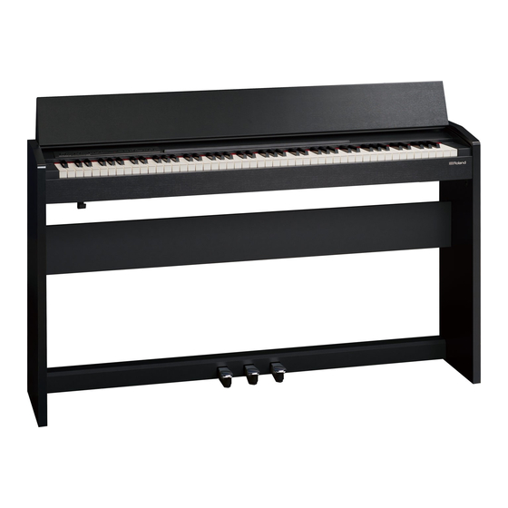
Piano main unit
2
Side board (left)
3
Side board (right)
4
Rear board
5
Pedal board
3
6
Screws (6 x 18 mm): 6 pcs.
6
11
7
Screws (5 x 20 mm): 6 pcs.
7
8
Screws (4 x 14 mm): 6 pcs.
8
12
9
Screws (4 x 16 mm): 2 pcs.
9
10
Stabilizers (left/right)
11
Cord clamp: 2 pcs.
10
12
Headphone hook: 1 pcs.
3.
Remove the protective material attached to the left and
right of the piano main unit, and stand it upright on your
work surface.
* The protective sheet that is wrapped around the piano main unit
must not be removed until you connect the pedal cord (step 9).
Removing the protective sheet before that time will allow the
keyboard cover to open, which may be hazardous.
* Avoid grasping the unit by the keyboard lid when lifting it.
4.
Attach the side board (right) and side board (left) to the piano
main unit, and use the screws (6 x 18 mm) to fasten them
7
2
6
7
-
0
1
*
provisionally.
Screws (6 x 18 mm): use four
If you nd that it's hard to get the screws to enter
their holes, try pushing the piano in the direction
shown by the arrow; you should then be able to
fasten the screws.
5.
Attach the rear board to the side boards, and use the screws
(5 x 20 mm) to fasten it provisionally.
6.
Place the unit upright, and attach the stabilizers to the side
boards.
* Securely fasten the stabilizers to their nal tightness at this time.
Right
7.
Attach the pedal board, and provisionally fasten it using the
screws (6 x 18 mm).
Avoid scratches!
8.
Securely tighten each screw (twelve locations) in the order
of the side boards, rear board, and pedal board.
screws
9.
Connect the AC adapter to the DC In connector on the
back of the piano, and connect the pedal cord to the Pedal
connector. Attach the cord clamps to fasten the pedal cord
and the AC adaptor cord (two locations).
Avoid scratches!
Screws (5 x 20 mm):
use six screws
10.
Use screws (4 x 16 mm) to fasten the headphone hook.
Screws (4 x 14 mm):
use six screws
Stabilizers
11.
Left
Connect the supplied AC adaptor and power cord.
Screws (6 x 18 mm):
use two screws
Placing the pedal
board (as seen from
the side)
Pedal board
When moving the unit
If you need to move the unit, close the keyboard cover and disconnect the AC
adaptor. With at least one other person helping you, lift the unit horizontally and
carry it, taking care not to pinch your hands or drop the unit on your feet.
Metal parts
Do not allow a gap
between the side
board and the main
1
unit.
2
1
3
2
3
Screws (4 x 16 mm): use two
screws
Power cord
To AC outlet
Place the AC adaptor so the side with the indicator faces upwards and
the side with textual information faces downwards. The indicator will
light when you plug the AC adaptor into an AC outlet.
1

Verwandte Anleitungen für Roland F-140R


Inhaltszusammenfassung für Roland F-140R
-
Seite 2: Überprüfen Des Lieferumfangs
Copyright © 2015 ROLAND CORPORATION Wenn Sie feststellen, dass sich die Schrauben Alle Rechte vorbehalten. Diese Publikation darf weder ganz noch teilweise in keiner Form ohne schriftliche Genehmigung durch die ROLAND CORPORATION reproduziert werden. nur schwierig in die Bohrungen einsetzen lassen, versuchen Sie, das Klavier in Pfeilrichtung zu drücken.