Herunterladen Inhalt Inhalt Diese Seite drucken

Werbung

Verfügbare Sprachen
  • DE

Verfügbare Sprachen

  • DEUTSCH, seite 18
Consolle
Marlene
ISTRUZIONI PER IL MONTAGGIO
ASSEMBLY INSTRUCTIONS
MONTAGEANLEITUNG
INSTRUCTIONS DE MONTAGE
INSTRUCCIONES DE MONTAJE
ИНСТРУКЦИЯ ПО СБОРКЕ

Werbung

Inhaltsverzeichnis
loading

Inhaltszusammenfassung für Devon & Devon Marlene

  • Seite 1 Consolle Marlene ISTRUZIONI PER IL MONTAGGIO ASSEMBLY INSTRUCTIONS MONTAGEANLEITUNG INSTRUCTIONS DE MONTAGE INSTRUCCIONES DE MONTAJE ИНСТРУКЦИЯ ПО СБОРКЕ...
  • Seite 2: Prima Di Iniziare

    Vi ringraziamo per aver scelto un prodotto Devon&Devon. Vi preghiamo cortesemente di leggere questo manuale prima di installare il prodotto. PRIMA DI INIZIARE Verificare le predisposizioni d’impianto necessarie prima del montaggio. Verificare la presenza di tutti gli articoli al’interno dell’imballo tramite il Packing List riportato alla pagina seguente.
  • Seite 3: Packing List

    PACKING LIST (STRUTTURA) A: Struttura metallica (x1) B: Gambe (x2) C: Viti e tasselli di fissaggio a muro per struttura metallica (x4) D: Viti a brugola di fissaggio gambe (x4)
  • Seite 4 PACKING LIST (LAVABO) E: Lavabo in ceramica (x1) F: Staffe a “S” (x2) (Viti e Tasselli non forniti da Devon&Devon)
  • Seite 5: Istruzioni Di Montaggio

    ISTRUZIONI DI MONTAGGIO Dopo avere rimosso i componenti della struttura dall’imballo posizionare la parte superiore della gamba (B) in corrispondenza delle forature presenti sulla struttura metallica (A). Fissare le gambe alla struttura tramite le viti a brugola (D) e una chiave a brugola da 5 mm.
  • Seite 6 Presentare a muro la struttura così assemblata. Verificare il posizionamento della struttura tramite una livella in direzione sia parallela che ortogonale a muro. Tracciare i fori di fissaggio Con una chiave a brugola da della struttura a muro. smontare barra distanziatrice sul retro della struttura, svitando le due viti che la fissano.
  • Seite 7 Rimuovere la struttura ed eseguire i 4 fori in base alla tracciatura. Inserire nei fori i tasselli (C) in dotazione, posizionare di nuovo la struttura e fissarla con le viti anch’esse incluse nella dotazione. Appoggiare sulla struttura il lavabo (E), cercando un buon compromesso tra l’appoggio sulla struttura e l’appoggio a muro.
  • Seite 8 Una volta raggiunto il miglior compromesso possibile, posizionare le staffe ad “S” (F) sotto al lavabo e tracciare i fori (2 per ciascuna staffa) per il loro fissaggio. A questo punto è possibile rimuovere il lavabo, eseguire le forature a muro, rispettando le tracciature. Montare le staffe di supporto del lavabo, fissandole con viti e tasselli (non forniti in dotazione).
  • Seite 9 Posizionare di nuovo il Applicare il silicone tra il lavabo, inserendo parte lavabo ed il muro. posteriore tra le staffe ed il muro. Al termine la consolle dovrebbe apparire come mostrato.
  • Seite 10: Before You Begin

    Thank you for choosing a Devon&Devon product. Please read this manual before installing the product. BEFORE YOU BEGIN Please check the existing layout of the system required before assembly. Verify the presence of all items inside the package using the Packing List included in the following page.
  • Seite 11 PACKING LIST (STRUCTURE) A: Metal structure (x1) B: Legs (x2) C: Screws and rawlplugs to attach the metal structure to the wall (x4) D: Allen screws to attach legs (x4)
  • Seite 12 PACKING LIST (BASIN) E: Ceramic basin (x1) F: S-shaped brackets (x2) (Screws and Rawplugs not provided by Devon&Devon)
  • Seite 13 ASSEMBLY INSTRUCTIONS After having removed the structure components from the packaging, place the top part of the leg (B) to correspond with the holes on the metal structure (A). Fasten the legs to the structure using the Allen screws (D) and a 5 mm Allen wrench.
  • Seite 14 Put the structure as assembled up against the wall. Verify the positioning of the structure using a level, in both a perpendicular and a parallel position to the wall. Mark the position of the holes Use a 3 mm Allen wrench on the wall to fit the structure.
  • Seite 15 Remove the structure from the wall and drill the 4 holes as marked. Place the rawlplugs (C) supplied in the holes. Position the structure again and fasten it using the screws, which are also supplied. Place the New Etoile basin (E) on to the structure, trying to find a good compromise between having it lean on to the structure and on to the wall.
  • Seite 16 Once you have obtained the best possible compromise, position the “S” shaped brackets (F) under the basin, and mark the position of the holes (2 for each bracket) to fasten them. At this point, it is possible to remove the basin and make the holes in the wall following the markings.
  • Seite 17 Position the basin once Apply silicon between the again, inserting the back part basin and the wall. between the brackets and the wall. Once you have finished, the console should look as shown.
  • Seite 18: Bevor Sie Anfangen

    Wir danken Ihnen, dass Sie sich für ein Produkt von Devon&Devon entschieden haben und bitten Sie, diese Anleitung zu lesen, bevor Sie das Produkt installieren. BEVOR SIE ANFANGEN Überprüfen Sie vor der Montage die nötigen Vorrichtungen in IhremBadezimmer. Überprüfen Sie mit Hilfe der Packing List auf der nächsten Seite, ob in der Verpackung alle Artikel vorhanden sind.
  • Seite 19 PACKING LIST (GESTELL) A: Metallstruktur (x1) B: Beine (x2) C: Schrauben und Dübel für die Wandfixierung der Metallstruktur (x4) D: Inbusschrauben für die Beinfixierung (x4)
  • Seite 20 PACKING LIST (WASCHBECKEN) E: Keramikwaschbecken (x1) F: S-förmige Bügel (x2) (Schrauben und Dübel werden nicht mitgeliefert)
  • Seite 21 MONTAGEANLEITUNG Entfernen aller Verpackungsteile. Nun die Metallbeine (B) mit der Oberseite zu den Öffnungen an der Metallstruktur (A) ausrichten. Die Beine an die Metallstruktur mit Hilfe der Inbusschrauben (D) und eines 5 mm Inbusschlüssels festschrauben. Die genannten Operationen für beide Beine wiederholen.
  • Seite 22 Die so zusammengestellte Struktur an die Wand stellen. Mit Hilfe einer Wasserwaage die korrekte Positionierung der Struktur sowohl parallel als auch rechtwinklig zur Wand nachprüfen. An der Wand Löcher markieren Mit einem Inbusschlüssel für die Anbringung der Struktur den 3 mm Abstandhalter auf an die Wand.
  • Seite 23 Struktur entfernen, Löcher ausführen gemäß Markierungen, mitgelieferte Wanddübel anbringen, Metallstruktur erneut den Dübeln entsprechend positionieren und mit Hilfe der mitgelieferten Schrauben festziehen. Das Waschbecken (E) auf die Metallstruktur legen. Dabei sollte ein guter Kompromiss zwischen der Abstützung durch die Struktur und der Abstützung durch die Wand gefunden werden.
  • Seite 24 Sobald der bestmögliche Kompromiss gefunden ist, die S-Bügel (F) unter das Waschbecken positionieren und Löcher markieren (2 für jeden Bügel) für ihre Fixierung. Das Waschbecken nun wieder entfernen und die Wandbohrungen gemäß den Markierungen durchführen. Die S-Bügel nun anbringen mit Hilfe von Schrauben und Dübeln, die nicht Teil der Lieferung sind.
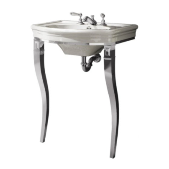
  • Seite 25 Das Waschbecken erneut Silikon zur Abdichtung positionieren, indem der rückwärtige des Waschbeckens zur Wand Teil zwischen den Bügeln und hin verwenden. der Wand eingelassen wird. Zum Schluss sollte die Consolle wie in der Abbildung erscheinen.
  • Seite 26: Avant De Commencer

    Nous vous remercions d’avoir choisi un produit Devon&Devon et vous prions de lire ce manuel avant d’installer le produit. AVANT DE COMMENCER Vérifier les dispositions d’installation nécessaires avant le montage. Vérifier la présence de tous les articles à l’intérieur de l’emballage grâce à...
  • Seite 27 LISTE DES ACCESSOIRES (STRUCTURE) A: Structure métallique (x1) B: Pattes (x2) C: Vis et chevilles pour fixer la structure métallique au mur (x4) D: Vis Allen pour fixer les pattes (x4)
  • Seite 28 LISTE DES ACCESSOIRES (LAVABO) E: Lavabo en céramique (x1) F: Étriersen “S” (x2) (Vis et Chevilles non fournies par Devon&Devon)
  • Seite 29: Montage

    MONTAGE Après avoir retiré de l’emballage les accessoires de la structure, positionner la partie supérieure de la patte (B) à hauteur des trous présents sur la structure métallique (A). Fixer les pattes à la structure à l’aide des vis Allen (D) et d’une clé...
  • Seite 30 Appuyer au mur la structure ainsi assemblée. Vérifier le positionnement de la structure à l'aide d'un niveau dans la direction parallèle ainsi qu'orthogonale au mur. Tracer les trous pour fixer la A l’aide d’une clé Allen de structure au mur. 3 mm démonter la barre entretoise sur la partie arrière de la structure, en dévissant les...
  • Seite 31 Enlever la structure et effectuer les 4 trous selon le traçage. Introduire les chevilles (C) dans les trous, repositionner la structure et la fixer à l’aide des vis déjà fournies. Poser le lavabo (E) sur la structure, en cherchant un bon compromis entre l’appui sur la structure et l’appui au mur.
  • Seite 32 Après avoir trouvé le meilleur compromis possible, positionner les étriers en “S” (F) au-dessous du lavabo et tracer les trous (2 par chaque étrier) pour leur fixation. A ce point, il est possible d’enlever le lavabo, effectuer les trous au mur en respectant les traçages. Monter les étriers de support du lavabo, en les fixant à...
  • Seite 33 Repositionner le lavabo, en Appliquer le silicone entre introduisant partie le lavabo et le mur. postérieure entre les étriers et le mur. A la fin, la console doit se présenter comme sur l’illustration ci-contre.
  • Seite 34: Antes De Comenzar

    Les agradecemos por haber elegido un producto Devon&Devon. Les rogamos que lean este manual antes de instalar el producto. ANTES DE COMENZAR Comprobar las predisposiciones para instalación necesarias antes del montaje. Comprobar que todos los artículos se encuentran en el interior del embalaje mediante la lista de contenido (ver página siguiente) y que ninguno de sus componentes presenta defectos visibles.
  • Seite 35 LISTA DE CONTENIDO (ESTRUCTURA) A: Estructura de metal (x1) B: Patas (x2) C: Tornillos y tacos de fijación a la pared para la estructura de metal (x4) D: Tornillos Allen de fijación patas (x4)
  • Seite 36 LISTA DE CONTENIDO (LAVABO) E: Lavabo de cerámica (x1) F: Pletinas en “S” (x2) (Tornillos y Tacos no proporcionados por Devon&Devon)
  • Seite 37: Instrucciones De Montaje

    INSTRUCCIONES DE MONTAJE Después de haber sacado de sus embalajes los componentes de la estructura, coloque la parte superior de la pata (B) en correspondencia de los agujeros presentes en la estructura de metal (A). Fije las patas a la estructura utilizando los tornillos Allen (D) y una llave Allen de 5 mm.
  • Seite 38 Apoye en la pared la estructura recién montada, comprobando su colocación con un nivel en dirección paralela y ortogonal respecto a la pared. Marque en la pared los Con una llave Allen de 3 mm, agujeros para fijar la estructura. desmonte la barra distanciadora situada en la parte trasera de la estructura, desenroscando los...
  • Seite 39 Aparte de la pared la estructura y efectúe los 4 agujeros en los puntos marcados. Introduzca en los agujeros los tacos (C) proporcionados y vuelva a colocar otra vez la estructura fijándola con los tornillos que también se incluyen en la dotación. Apoye el lavabo (E) sobre la estructura, buscando el justo equilibrio entre el apoyo sobre la estructura y el apoyo en la pared.
  • Seite 40 Una vez que quede bien apoyado y equilibrado, coloque las pletinas acodadas (F) debajo del lavabo y marque los agujeros (2 por cada pletina) para su fijación. A este punto es posible apartar el lavabo y realizar los agujeros en la pared en los puntos marcados. Monte las pletinas de soporte del lavabo fijándolas con Tornillos y Tacos (no proporcionados).
  • Seite 41 Coloque otra vez el lavabo Selle con silicona la zona introduciendo su parte posterior de contacto entre el lavabo y la entre las pletinas y la pared.. pared. Al final, el lavabo de consola debe presentar el aspecto mostrado en la imagen.
  • Seite 42: Перед Началом Сборки

    Благодарим за выбор изделия Devon&Devon. Перед установкой внимательно прочитайте настоящую инструкцию. ПЕРЕД НАЧАЛОМ СБОРКИ Перед тем, как приступать к сборке, убедиться в наличии всех элементов структуры. Проверить наличие всех деталей внутри упаковки, в соответствии с Упаковочным листом, приведенным на следующей странице. Убедиться, что...
  • Seite 43: Упаковочный Лист

    УПАКОВОЧНЫЙ ЛИСТ (ОСНОВНАЯ КОНСТРУКЦИЯ) A: Рама металлическая (x1) B: Ножки (x2) C: Винты с дюбелями для крепления металлической рамыкстене (x4) D: Винты под ключ-шестигранник для крепления ножек (x4)
  • Seite 44 УПАКОВОЧНЫЙ ЛИСТ (РАКОВИНА) E: Керамическая раковина (x1) F: S-образные кронштейны (х2) (винты и дюбели не поставляются Devon&Devon)
  • Seite 45: Инструкция По Сборке

    ИНСТРУКЦИЯ ПО СБОРКЕ Освободив все детали конструкции от упаковки, совместите отверстия на верхнем торце ножек (В) с соответствующими отверстиями в металлической раме (А). Привинтите первую ножку к раме с помощью винтов код ключ-шестигранник (D) и ключа-шестигранника на 5 мм. Проделайте ту же операцию с другой ножкой.
  • Seite 46 Собранную таким образом конструкцию приставьте к стене. Проверьте с помощью уровня её параллельность и перпендикулярность относительно стены. Наметьте отверстия для С помощью торцевого крепления рамы к стене. ключа-шестигранника на 3 мм снимите распорный брусок с задней части рамы, отвинтив два держащих его винта.
  • Seite 47 Отставьте в сторону раму, просверлите в стене ранее намеченные 4 отверстия, вставьте в них имеющиеся в комплекте дюбели (С), вновь приставьте раму к стене и прикрепите её винтами (также имеются в комплекте). Установите на раму раковину (Е), уравновесьте нагрузку на раму...
  • Seite 48 Отрегулировав положение раковины, установите под ней S–образные скобы (F) и наметьте крепежные отверстия (по 2 на каждую скобу). Теперь можно снять раковину и просверлить в стене намеченные отверстия. Установите скобы крепления раковины, привинтив их к стене с помощью винтов и дюбелей (в комплект поставки не входят).
  • Seite 49 Установите раковину на место, Заделайте силиконовым надев её на закрепленные на герметиком стык между стене скобы. раковиной и стеной. По завершении установки консоль должна выглядеть следующим образом.
  • Seite 50 Devon & Devon Viale A.Volta, 46 - 50131 Firenze Tel. 0039 055 5001173 - Fax 0039 055 5000628 www.devon-devon.com email: office@devon-devon.com...

Inhaltsverzeichnis