Herunterladen Inhalt Inhalt Diese Seite drucken
Siemens Sitrans F Serie Schnellstartanleitung

Siemens Sitrans F Serie Schnellstartanleitung

Durchflussmessgerät
Vorschau ausblenden Andere Handbücher für Sitrans F Serie:
Inhaltsverzeichnis

Werbung

Verfügbare Sprachen

Verfügbare Sprachen

Ultrasonic Flowmeters
SITRANS FUE1010 IP40 NEMA 1 Portable
Quick Start - 05/2009
SITRANS F

Werbung

Inhaltsverzeichnis
loading

Inhaltszusammenfassung für Siemens Sitrans F Serie

  • Seite 1 Ultrasonic Flowmeters SITRANS FUE1010 IP40 NEMA 1 Portable Quick Start - 05/2009 SITRANS F...
  • Seite 3 Introduction Installation Commissioning SITRANS Troubleshooting Ultrasonic Flowmeters FUE1010 IP40 (NEMA 1) Energy Appendix A Portable Compact Operating Instructions 5/2009 A5E02384186-03...
  • Seite 4: Qualified Personnel

    Note the following: WARNING Siemens products may only be used for the applications described in the catalog and in the relevant technical documentation. If products and components from other manufacturers are used, these must be recommended or approved by Siemens. Proper transport, storage, installation, assembly, commissioning, operation and maintenance are required to ensure that the products operate safely and without any problems.
  • Seite 5: Inhaltsverzeichnis

    Table of contents Introduction..............................5 Introduction............................5 Items supplied..........................5 Installation..............................7 Application Guidelines........................7 Commissioning............................15 Navigating the Menu........................16 Setting the Parameters........................18 Sensor Installation........................23 3.3.1 General information........................23 3.3.2 Installing the Sensors........................24 3.3.3 Final Setup..........................27 Troubleshooting............................29 Troubleshooting...........................29 Alarm Letter Codes and Descriptions..................31 Appendix A..............................33 I/O Connections and Wiring......................33 Technical Data..........................34 FUE1010 IP40 (NEMA 1) Energy Portable Compact Operating Instructions, 5/2009, A5E02384186-03...
  • Seite 7: Introduction

    Introduction Introduction This Quick Start Guide is for the Siemens SITRANS FUE1010 IP40 (NEMA 1) Portable Flowmeters. It includes procedures to form and charge the battery pack and use the AC Power Adapter. It also illustrates a typical set using D-Series transducers in the Reflect operating mode (for Direct Mode see flowmeter manual).
  • Seite 9: Installation

    Installation Application Guidelines Basic Requirements ● Determine pipe material and dimensions. ● Avoid vertical pipes flowing in a downward direction. ● Avoid installation of transducers on the top and bottom of horizontal pipes, if possible. ● Select a location with the longest straight run of pipe. ●...
  • Seite 10 Installation 2.1 Application Guidelines ① IEC 320 Power Inlet ② Connector ③ 0,9 meters minimum (3 ft) ④ NEMA 5 - 15P (see Power Cord table) ⑤ IEC 320 Plug (see Power Cord table) Figure 2-1 Power Adapter/Battery Charger Table 2-1 Power Cord Codes Assembly P/N POWER CORD...
  • Seite 11: Battery Operation

    Installation 2.1 Application Guidelines 1015BCK-1 NEM 5-15P 10A / 120VAC 1015BCL-1 SEV 1011 10A / 250VAC Battery Operation All portable systems include battery chargers that operate from an AC voltage source. We strongly recommend that you "form" and charge the battery before operating the system for the first time.
  • Seite 12 Lead/Acid battery design that features a deep discharge cycle for extended operation. CAUTION Do not use any other external Battery Charger/Pack combination with the flowmeter unless reviewed and pre-approved by Siemens. CAUTION Do not leave the Battery Charger connected to the Battery Pack during transportation or storage.
  • Seite 13 Installation 2.1 Application Guidelines ① Battery Lead Acid Gel (12VDC, 3 AH) ② Female "Cigarette" Connector ③ Adapter Cable 1.22 meters Extended (4 ft) Figure 2-2 External Battery Pack Charging the External Battery Pack FUE1010 IP40 (NEMA 1) Energy Portable Compact Operating Instructions, 5/2009, A5E02384186-03...
  • Seite 14 Installation 2.1 Application Guidelines DANGER Attempting to use the unit in a submerged environment with the cover open or latches not engaged will result in damage to the unit that cannot be repaired and could expose the user to the risk of electric shock. CAUTION Charge the 1015BB Battery Pack (7ME39403BB00) in a completely dry environment only.
  • Seite 15 Installation 2.1 Application Guidelines 3. Plug the 1015BCK-2 Adapter/Battery Charger (USA) (7ME39403BC10) or 1015BCA-2 (EURO) (7ME39403BC20) AC power cord into a proper AC source. Plug the Battery Charger DC output cable into the DC input connector on the 1015BB Battery Pack. 4.
  • Seite 16 Installation 2.1 Application Guidelines Status Indication Action Battery Warning Beeper Normal operation, periodic audible alarm Connect a Battery Charger for continued operation. Battery Discharge Unit will not turn on (no display screen) Connect to Battery Charger for at least 1.5 hours before attempting to operate. FUE1010 IP40 (NEMA 1) Energy Portable Compact Operating Instructions, 5/2009, A5E02384186-03...
  • Seite 17: Commissioning

    Commissioning Connecting AC Power Using the 1015BCK-1 (7ME39404PG00) Power Adapter/Charger 1. Connect the AC power cord to the AC Cord input of the Power Adapter/Charger. 2. Plug the Power adapter connector into the rear panel Power input connector. ① AC Cord Input ②...
  • Seite 18: Navigating The Menu

    3.1 Navigating the Menu 1. Plug charger into an AC outlet. Within 10 seconds of power-up the flowmeter main display will become active and a typical Siemens graphic will briefly appear. The screen also identifies the software version of the unit.
  • Seite 19 Commissioning 3.1 Navigating the Menu Figure 3-2 Key Pad Note Use <Left Arrow> key to return to previous menus. Table 3-1 Key Pad Function Chart Keys Description MENU Press to activate the Installation Menu. Store numeric data, select from option lists, etc. Left / Right Arrows Menu navigation keys move cursor.
  • Seite 20: Setting The Parameters

    Commissioning 3.2 Setting the Parameters ① ⑤ Menu Cell Data (left-hand column) Current Selected Measurement Channel ② ⑥ Highlighted Menu Cell Site Name Identified ③ ⑦ Menu Prompt Line (Reverse Video) Highlighted Data ④ ⑧ Current Selected Meter Type Menu Cell Data (right-hand column) Figure 3-3 Typical Installation Menu Screen Example Setting the Parameters...
  • Seite 21 Commissioning 3.2 Setting the Parameters Select a Meter Type 1. Press the <MENU> key and select the Meter Type. 2. Press the Right Arrow> and scroll to [Dual Chan Energy] Note Select [2 Chan Energy] if measuring two different pipes and [2 Path Energy] if sensors are mounted on the same pipe.
  • Seite 22 Commissioning 3.2 Setting the Parameters 3. Press <ENT> to create Site name (e.g., ABC). (See figure below.) Note To set English or Metric units: In the Meter Type menu, scroll to Meter Facilities Menu. Press <Right Arrow> and select desired units. Press <ENT> to select. Press <Left Arrow> and <Up Arrow>...
  • Seite 23 Commissioning 3.2 Setting the Parameters Select Liquid Class 1. Press the <Down Arrow> and scroll to [Application Data]. 2. Press the <Right Arrow> to select [Liquid Class]. 3. Press the <Right Arrow> again and scroll to desired liquid. 4. Press <ENT> to save selection. ①...
  • Seite 24 Commissioning 3.2 Setting the Parameters Table 3-2 Pipe Configuration Option List Definitions Options Definitions Fully Developed Fully developed flow, as would be expected for very long straight pipe runs or installation downstream of a flow condition. 1 Elbow Single 90 degree Elbow upstream of transducer installation. Dble Elbow+ Double out-of-plane Elbows upstream of transducer installation.
  • Seite 25: Sensor Installation

    Commissioning 3.3 Sensor Installation Transducer Identification The transducer part number located on the front face provides a detailed identification. For Part Number: 1011PPS-D1 means: example, the ① Model ② Size Note Check to make sure that the transducers are a matched set with the same serial numbers and marked with an "A"...
  • Seite 26: Installing The Sensors

    Commissioning 3.3 Sensor Installation ● Tape, chalk and a ruler or measuring tape ● Mounting Straps ● Spacer Bar ● Mounting Guide (for Direct Mount) ● Ultrasonic coupling compound ● Transducers (matched set) 3.3.2 Installing the Sensors. Reflect Mount using Mounting Frames and Spacer Bar 1.
  • Seite 27 Commissioning 3.3 Sensor Installation Note Minimum Ltn 18mm (0.75 in) Installation Procedure (See figure for reference) 1. On a flat surface, attach the Spacer Bar to a Mounting Frame so that the Reference Hole on the Spacer Bar fits over the metal post on the platform of the frame. Tighten the clamping screw.
  • Seite 28 Commissioning 3.3 Sensor Installation 10.Take either sensor and apply a continuous lengthwise 1/8-inch bead of coupling compound across the center of the sensor emitting surface. ① ④ F-Connector Back End ② ⑤ Angled Edge Emitting Surface ③ ⑥ Sensor Coupling Compound Figure 3-5 Sensor ①...
  • Seite 29: Final Setup

    Commissioning 3.3 Sensor Installation 11.Slide sensor into a mounting frame back end first aligning the angled edge of the sensor with the angled edge of the mounting frame. Keep sensor from making contact with the pipe until it butts up against the mounting frame stop. Push sensor down to mate with pipe. Repeat procedure 12.Tighten the sensor clamping screws to hold the sensor firmly in place.
  • Seite 30 Commissioning 3.3 Sensor Installation 3. Press the <Down Arrow> to accept sound velocity value. 4. The meter is now ready to report flow. Press the <MENU> key twice to display flow. Figure 3-8 Final Setup Figure 3-9 Measuring Flow See also Refer to I/O Connection tables (Page 33) for input/output wiring and flowmeter manual for data spanning procedures.
  • Seite 31: Troubleshooting

    The following is list of troubleshooting tips and messages that you may encounter. They include explanations and, in some cases, a recommended action. If a problem seems unsolvable, contact your local Siemens office or regional Ultrasonic Flow Representative for expert help at http://www.automation.siemens.com/partner (http://www.automation.siemens.com/...
  • Seite 32 However, operation may not be possible if there is poor liquid or pipe wall sonic conductivity. Note If you receive a Detection Fault message, it is strongly recommended that the Technical Service Department (http://www.automation.siemens.com/partner) be contacted. FUE1010 IP40 (NEMA 1) Energy Portable Compact Operating Instructions, 5/2009, A5E02384186-03...
  • Seite 33: Alarm Letter Codes And Descriptions

    Troubleshooting 4.2 Alarm Letter Codes and Descriptions Alarm Letter Codes and Descriptions Alarm Letter Codes The following alarm codes appear on the main display of the flowmeter. Table 4-2 Alarm Codes and Descriptions Letter Codes Alarm Code Description SPACE Spacing Transducer spacing may need adjustment EMPTY Empty...
  • Seite 34 Troubleshooting 4.2 Alarm Letter Codes and Descriptions ① Alarm Codes FUE1010 IP40 (NEMA 1) Energy Portable Compact Operating Instructions, 5/2009, A5E02384186-03...
  • Seite 35: Appendix A

    Appendix A I/O Connections and Wiring Terminal Block Wiring - FUE1010 IP40 (NEMA 1) Battery Powered Dual Channel/Dual Path Flowmeter Wiring (Refer to manual drawing 1010EWDP-7 sheet 2 of 2) The terminal block wiring table applies to the part numbers listed below. Table A-1 Part Numbers and Connection Data 1010EWDP-7 (Sheet 2 of 2) Drawing...
  • Seite 36: Technical Data

    Appendix A A.2 Technical Data Pin# Signal Function Description No Connection Signal Ground Return For Signals Technical Data Techncial Data Temperature Range Degree of Protection Operating: -18°C to 60°C (0°F to 140°F) IP40 (NEMA 1) Storage: -20°C to 60°C (-4°F to 140°F) FUE1010 IP40 (NEMA 1) Energy Portable Compact Operating Instructions, 5/2009, A5E02384186-03...
  • Seite 37 Yes/No Logger Setup Logger Mode Enter From List Logger Data Enter From List Logger Interval Enter From List Siemens Industry, Inc. Logger Events Enter From List Industry Automation Division Display Logger Enter From List CoC Ultrasonic Flow I/O Data Control...
  • Seite 38 FUE1010 IP40 (NEMA 1) Installation Menu Chart LEVEL A LEVEL B LEVEL C LEVEL D LEVEL E LEVEL F LEVEL G LEVEL H Diagnostic Data Energy Data Enter From List Flow Data Enter From List Application Info Enter From List Liquid Data Enter From List Site Setup Data...
  • Seite 41 Siemens Industry, Inc. Industry Automation Division CoC Ultrasonic Flow Hauppauge, New York 11788 USA Web: www.usa.siemens.com Sonic Velocity Relative to Temperature of Pure Water Temperature Velocity Temperature Velocity Temperature Velocity °F °C °F °C °F °C -17.8 1292.45 100.0 37.8 1525.03...
  • Seite 43 Einleitung Anschließen Bedienen (Hardware) SITRANS Alarm-, Fehler- und Systemmeldungen Durchflussmessgerät FUE1010 Troubleshooting/FAQs Quick Start Guide Anhang Betriebsanleitung 5/2009 CQO:QSG007 Revision 03...
  • Seite 44: Qualifiziertes Personal

    Siemens-Produkte dürfen nur für die im Katalog und in der zugehörigen technischen Dokumentation vorgesehenen Einsatzfälle verwendet werden. Falls Fremdprodukte und -komponenten zum Einsatz kommen, müssen diese von Siemens empfohlen bzw. zugelassen sein. Der einwandfreie und sichere Betrieb der Produkte setzt sachgemäßen Transport, sachgemäße Lagerung, Aufstellung, Montage, Installation, Inbetriebnahme, Bedienung und Instandhaltung voraus.
  • Seite 45 Inhaltsverzeichnis Einleitung..............................5 Einführung............................5 Menüaufbau und -navigation ......................7 Anschließen............................... 9 Anschluss an Wechselstromnetz oder Batterie ................9 Bedienen (Hardware)..........................15 Programmieren des Durchflussmessgerätes................15 Transducer-Installation ........................20 Alarm-, Fehler- und Systemmeldungen ....................27 Buchstabencodes und Beschreibungen der Alarme ..............27 Troubleshooting/FAQs..........................29 Fehlerbehebung...........................29 Anhang ..............................33 E/A-Anschlüsse und -Verdrahtung ....................33 Technische Daten ........................35 Tabellen...
  • Seite 46 Inhaltsverzeichnis Bild 2-2 Batterie-Ladegeräte 1015BCK-2 und 1015BCA-2..............12 Bild 2-3 Netzadapter/WS-Ladegerät für Einkanal- und Zweikanal-Durchflussmessgeräte ..... 13 Bild 3-1 Reflekt-Montage mit Montagerahmen und Abstandshalter (Ansicht von vorne) ......21 Bild 3-2 Transducer - Abbildungslegende ....................23 Bild 3-3 Transducer-Installation........................ 23 Bild 3-4 Anschließen der Transducer an das Durchflussmessgerät ............
  • Seite 47: Einleitung

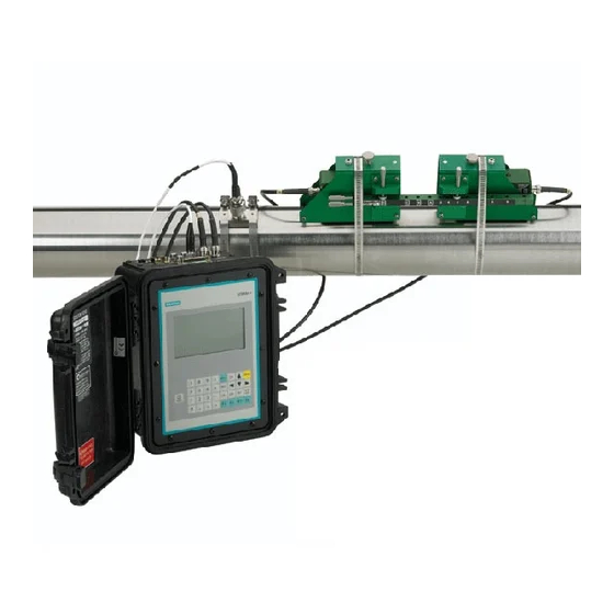
    Einführung Der vorliegende Quick Start Guide behandelt die tragbaren und wasserdichten Durchflussanzeigerechner Sitrans FUE1010 IP40 (NEMA 1) von Siemens. Er enthält Verfahren zum Anpassen und Aufladen der Batterien und zum Gebrauch des WS- Netzadapters. Es wird eine typische Installation und Konfiguration unter Verwendung von Transducern der D-Serie im Reflekt- und Direkt-Modus dargestellt (Informationen zum Direkt-Modus enthält das Handbuch zum Durchflussmessgerät).
  • Seite 48: Batterieladegerät

    Einleitung 1.1 Einführung Batterie-Ladegerät Der Durchflussanzeigerechner FUE1010 ist wahlweise mit einem Batterie-Ladegerät erhältlich, das an eine Wechselstromquelle mit 100, 110 oder 220 V (50 oder 60 Hz) angeschlossen werden kann. Es verfügt über einen universellen Eingang, der keine Für den Anschluss an die Wechselstromnetze Umschaltung durch den Bediener erfordert.
  • Seite 49: Menüaufbau Und -Navigation

    Einleitung 1.2 Menüaufbau und -navigation Siehe auch Programmieren des Durchflussmessgerätes (Seite 15) Menüaufbau und -navigation Navigation im Installationsmenü Das Diagramm des Installationsmenüs zeigt die Menüebenen in drei Spalten von links nach rechts (=Menüebenen von oben nach unten). Ebene A - enthält die Hauptmenükategorien. Ebene B - enthält die der Ebene A zugeordneten Menüfelder.
  • Seite 50: Tabelle 1- 1 Tastenfunktionen - Übersicht

    Einleitung 1.2 Menüaufbau und -navigation Tabelle 1- 1 Tastenfunktionen - Übersicht Tasten Beschreibung MENU Aktiviert das Installationsmenü. Zum Speichern numerischer Daten, Auswählen aus Optionslisten usw. Linkspfeil/Rechtspfeil Menü-Navigationstasten zum Bewegen des Cursors. Aufwärts-/Abwärtspfeil Entsprechend Links- und Rechtspfeil. Zum Blättern in Optionslisten und der Grafik-Anzeige. Zum Löschen von Daten oder zur Auswahl von Listenoptionen.
  • Seite 51: Anschließen

    Anschließen Anschluss an Wechselstromnetz oder Batterie Batteriebetrieb Alle tragbaren Geräte enthalten Batterie-Ladegeräte, die an ein Wechselstromnetz angeschlossen werden können. Wir empfehlen, vor der ersten Inbetriebnahme die Batterie "anzupassen" und aufzuladen. Ladeanzeige-LED Eine Batterie-Statusanzeige zeigt den Zustand der internen Batterie und der Ladeschaltung. Die Anzeige-LED wechselt von Rot nach Grün, je nach dem Betrieb des Durchflussmessers.
  • Seite 52: Externe Batterie

    Batterie 1015BB ist eine spezielle Bleibatterie mit Tiefenentladung für den erweiterten Betrieb. VORSICHT Für den FUE1010 Durchflussanzeigerechner dürfen keine anderen Batterie-/Ladegeräte- Kombinationen verwendet werden, sofern sie nicht von Siemens geprüft und freigegeben sind. VORSICHT Bei Transport und Lagerung ist das Batterie-Ladegerät von der Batterie zu trennen. Sonst kann der Batterie-/Ladegerätstecker geschädigt oder eine Entladung der Batterie...
  • Seite 53 Anschließen 2.1 Anschluss an Wechselstromnetz oder Batterie Aufladen der externen Batterie GEFAHR Der Einsatz des Geräts unter Wasser mit offener Abdeckung oder nicht eingerasteten Verschlüssen verursacht Schäden am Gerät, die nicht repariert werden können und kann zu Stromschlaggefahr für den Bediener führen. VORSICHT Die Batterie 1015BB (7ME39403BB00) nur in einer vollständig trockenen Umgebung aufladen.
  • Seite 54 Anschließen 2.1 Anschluss an Wechselstromnetz oder Batterie BESCOR AC ADAPTER Input: 120VAC 60Hz 12W Output: 12VDC 60Hz 12W Model No. DV-1250 Part No. BC500 Class 2 Transformer CAUTION: INDOOR USE ONLY ① Steckertyp CEE 7/16 (EUR) ② Steckertyp NEMA 1-15P (USA) ③...
  • Seite 55: Anschluss An Wechselstrom

    Netzadapter/WS-Ladegerät für Einkanal- und Zweikanal-Durchflussmessgeräte ● Das Ladegerät an eine WS-Steckdose anschließen. Innerhalb von 10 Sekunden nach dem Einschalten leuchtet die Hauptanzeige des Durchflussmessgeräts auf und zeigt ein typisches Siemens-Startbild. Auf dem Startbild erscheint auch die Software-Version des Geräts. SITRANS FUE1010 Quick Start Guide...
  • Seite 56 Anschließen 2.1 Anschluss an Wechselstromnetz oder Batterie ① Software-Version (x.xx.xx) ● Drücken Sie Taste <MENU>, um das Hauptmenü aufzurufen. SITRANS FUE1010 Quick Start Guide Betriebsanleitung, 5/2009, CQO:QSG007 Revision 03...
  • Seite 57: Bedienen (Hardware)

    Bedienen (Hardware) Programmieren des Durchflussmessgerätes Hinweis Vor dem Anlegen eines Messortes wählen Sie eine Sprache und dann im Menü [Messeinrichtung] als Maßeinheiten englische oder metrische Einheiten.* Funktionsart auswählen ● Taste <MENU> drücken und die Funktionsart auswählen. ● Betätigen Sie den <Rechtspfeil>, und blättern Sie zu [2 Kanal Energie]. Hinweis Wählen Sie [2 Kanal Energie] bei Messungen an zwei verschiedenen Rohren und [2 Pfad Energie], wenn die Transducer auf demselben Rohr montiert sind.
  • Seite 58 Bedienen (Hardware) 3.1 Programmieren des Durchflussmessgerätes Messort anlegen ● Bevor Sie fortfahren, vergewissern Sie sich, ob englische oder metrische Einheiten ausgewählt wurden.* ● Im Menü [Einst. Kanal] betätigen Sie den <Rechtspfeil> und geben den Namen eines Messorts ein. ● Drücken Sie <ENT>, um einen Messortnamen anzulegen (z. B. ABC). (Siehe nachstehende Abbildung.) Hinweis * So stellen Sie englische oder metrische Maßeinheiten ein: Blättern Sie im Menü...
  • Seite 59 Bedienen (Hardware) 3.1 Programmieren des Durchflussmessgerätes Rohrdaten Rohrklasse auswählen ● Betätigen Sie Taste <Rechtspfeil> zum Auswählen der Rohrklasse. Drücken Sie Taste <Rechtspfeil> erneut, und blättern Sie zur gewünschten Rohrklasse. ● Starten Sie die Auswahl mit <ENT>. ● In den Menüfeldern erscheinen werkseitig programmierte Maße für die Rohrgröße sowie die entsprechenden Rohrparameter.
  • Seite 60: Tabelle 3- 1 Definitionen Für Die Optionsliste Zur Rohranordnung

    Bedienen (Hardware) 3.1 Programmieren des Durchflussmessgerätes Rohranordnung ● Gehen Sie zu [Rohranordnung], und drücken Sie den <Rechtspfeil>. ● Wählen Sie eine Rohranordnung, die den Bedingungen stromaufwärts von Ihrer Transducer-Montagestelle nahe kommt. (Definitionen der verschiedenen Rohranordnungen s. unten.) ● Speichern Sie die Auswahl mit <ENT>. ①...
  • Seite 61 Bedienen (Hardware) 3.1 Programmieren des Durchflussmessgerätes Optionen Definitionen Kopf Zulauf Krümmer oder Verteilerrohr stromaufwärts von der Transducer-Montagestelle. Eintritte Derzeit nicht verfügbar. Transducer-Installation Nachfolgend ist ein typisches Installationsverfahren für D1H High-Precision-Transducer beschrieben. ● Drücken Sie den <Linkspfeil>, um in das Hauptmenü zurückzukehren. Drücken Sie im Hauptmenü...
  • Seite 62: Transducer-Installation

    Bedienen (Hardware) 3.2 Transducer-Installation Kennzeichnung der Transducer Die Transducer-Teilenummer auf der Vorderseite enthält eine detaillierte Kennzeichnung der Teilenummer 1011PPS-D1 Transducer. So bedeutet beispielsweise die 1011PPS - D1 ① Modell ② Größe Hinweis Vergewissern Sie sich, dass es sich bei den Transducern um ein zusammengehöriges, werkseitig abgestimmtes Paar mit der gleichen Seriennummer und den Zusatzkennungen “A”...
  • Seite 63: Montage Im Reflekt-Modus

    Bedienen (Hardware) 3.2 Transducer-Installation ● Abstandshalter ● Montagehilfe (für Direkt-Montage) ● Ultraschall-Koppelpaste ● Transducer (abgestimmtes, zusammengehöriges Paar) Transducer-Installation Montage im Reflekt-Modus Installation mit Montagerahmen und Abstandshalter ● Nach Ermittlung des Abstandsindex über das Installationsmenü bereiten Sie den für die Transducer-Montage vorgesehenen Bereich der Rohroberfläche vor. ●...
  • Seite 64 Bedienen (Hardware) 3.2 Transducer-Installation Vorgehensweise zur Installation (vgl. Abbildung 3) 1. Befestigen Sie auf einer ebenen Oberfläche den Abstandshalter an einem Montagerahmen so, dass der Anschlagstift der Montagerahmenklemme in die Referenzbohrung auf dem Abstandshalter passt. Ziehen Sie die Befestigungsschraube 2. Schieben Sie den zweiten Montagerahmen über das andere Ende des Abstandshalters, und richten Sie die Bohrung für den Nummernindex am Anschlagstift der Klemme aus (s.
  • Seite 65 Bedienen (Hardware) 3.2 Transducer-Installation ① Koppelpaste ④ Transducer ② Kontaktfläche ⑤ Abgeschrägte Seite ③ Rückseite ⑥ F-Stecker Bild 3-2 Transducer - Abbildungslegende ① Vorderansicht ⑥ Metallmontageband ② Klemmfeder (nicht bei allen Modellen ⑦ Hinweis: Abbildung zeigt ein vorhanden) optionales zweites Montageband. Bei Rohren mit größerem Durchmesser ist für eine stabile Befestigung ggf.
  • Seite 66 Bedienen (Hardware) 3.2 Transducer-Installation 11. Schieben Sie den Transducer mit der Rückseite voran in einen der Montagerahmen und richten die abgeschrägte Seite des Transducers an der abgeschrägten Seite des Montagerahmens aus. Der Transducer sollte das Rohr bei diesem Vorgang noch nicht berühren, sondern erst dann, wenn er den Anschlag des Montagerahmens erreicht hat.
  • Seite 67 Bedienen (Hardware) 3.2 Transducer-Installation Hinweis Die Ein-/Ausgangsverdrahtung ist den E/A-Anschlussplänen zu entnehmen. Die Messbereichseinstellungen finden Sie im Benutzerhandbuch des Durchflussmessgeräts. SITRANS FUE1010 Quick Start Guide Betriebsanleitung, 5/2009, CQO:QSG007 Revision 03...
  • Seite 69: Alarm-, Fehler- Und Systemmeldungen

    Alarm-, Fehler- und Systemmeldungen Buchstabencodes und Beschreibungen der Alarme Alarmbuchstabencodes Auf der Hauptanzeige des Durchflussmessers erscheinen die folgenden Alarmcodes. Tabelle 4- 1 Alarmcodes und Beschreibungen Buchstabencodes Alarmcode Beschreibung SPACE Abstand Transducerabstand muss eventuell neu eingestellt werden EMPTY Leerrohr Rohr ist leer HI/LO Durchflussrate Durchfluss über eingestelltem Wert für maximalen Durchfluss bzw.
  • Seite 70 Alarm-, Fehler- und Systemmeldungen 4.1 Buchstabencodes und Beschreibungen der Alarme 11.03 174.70 30.0 9/26 12:45 ① Alarmcodes SITRANS FUE1010 Quick Start Guide Betriebsanleitung, 5/2009, CQO:QSG007 Revision 03...
  • Seite 71: Troubleshooting/Faqs

    Hinweisen zur jeweiligen Meldung. Die Hinweise umfassen Erläuterungen und z. T. auch empfohlene Maßnahmen zur Fehlerbehebung. Erscheint dennoch ein Problem einmal unlösbar, setzen Sie sich mit den Experten der nächsten Siemens-Vertretung für den Bereich Ultraschall-Durchflussmessung unter www.siemens.com in Verbindung. Tabelle 5- 1 Tipps zur Fehlerbehebung...
  • Seite 72 Troubleshooting/FAQs 5.1 Fehlerbehebung Meldung Beschreibung Index Abst aend. Bei der Messung der flüssigkeitsspezifischen Schallgeschwindigkeit (Vs) benötigt das Messgerät einen anderen Transducer-Abstand, um die Messleistung zu verbessern. Invalid Setup (Direkt-Modus verwenden) Beim ersten Aufstart stellt der Rechner einen unzulässigen Transducer-Abstand, ungültige Flüssigkeits-/Rohrparameter oder andere Faktoren fest, die einen erfolgreichen Abschluss des ersten Aufstarts verhindern.
  • Seite 73 Troubleshooting/FAQs 5.1 Fehlerbehebung Meldung Beschreibung Low Signal - Press <ENT> Der Rechner erkennt beim ersten Aufstart, dass das vorhandene Messsignal für einen ordnungsgemäßen Betrieb nicht stark genug ist. Gründe für ein zu schwaches Signal können z. B. sein: Aufrufen von [Install. beendet] bei leerem Rohr. •...
  • Seite 75: Anhang

    Anhang E/A-Anschlüsse und -Verdrahtung Verdrahtung der Klemmleiste - Verdrahtung des FUE1010 NEMA IP40 (NEMA 1) Einkanal- Durchflussmessgeräts mit Batteriebetrieb (Siehe Zeichnung in Handbuch 1010EP-7 Blatt 2 von 2) Das Anschlussdiagramm bezieht sich auf die Teilenummern wie nachstehend aufgeführt: Tabelle A- 1 Teilenummern und Anschlussdaten Zeichnung 1010DP-7 (Blatt 2 von 2) FUE1010 7ME350a-bc...
  • Seite 76: Tabelle A- 3 Teilenummern Und Anschlussdaten

    Anhang A.1 E/A-Anschlüsse und -Verdrahtung Stift-Nr. Signal Beschreibung Ausgang 4 bis 20mA [0 bis 1 kOhm @ 30 V DC; 0 bis 450 Ohm @18 V DC] Io PWR Schleifenstromeingang für mA-Ausgänge [Benutzerbeistellung 18 bis 30 V DC @ 25 mA min.] Anschluss Signalrückleitung [24 GA.
  • Seite 77: Technische Daten

    Anhang A.2 Technische Daten Stift-Nr. Signal Funktion Beschreibung Kein Anschluss Log. Aus 2 Logischer Signalpegel (HIGH=5 bis 3 V DC; LOW=1 bis 0 V Kein Anschluss Log. Aus 3 Logischer Signalpegel (HIGH=5 bis 3 V DC; LOW=1 bis 0 V Kein Anschluss Log.
  • Seite 79: Übersicht Installtionsmenü Fue1010 Ip40 (Nema 1)

    Lin.diagr loesch Ja/Nein Loggereinst. Loggermodus Eingabe aus Liste Loggerdaten Eingabe aus Liste Loggerintervall Eingabe aus Liste Siemens Industry, Inc. Loggerereignisse Eingabe aus Liste Industry Automation Division Display Logger Eingabe aus Liste CoC Ultrasonic Flow E/A Datenkontr. Einstellg. AA Eingabe aus Liste Hauppauge, New York Relaiseinstellg.
  • Seite 80 Übersicht Installtionsmenü FUE1010 IP40 (NEMA 1) EBENE EBENE EBENE EBENE EBENE EBENE EBENE LEBENE Diagnosedaten D. flussdaten Eingabe aus Liste Anwendungs Info Eingabe aus Liste Fluessig.daten Eingabe aus Liste Ortskonf.daten Eingabe aus Liste Testeinrichtung Eingabe aus Liste Ortskonf. drucken Ja/Nein Messort vom (Datum): Schreibgeschützt mm.dd.yy hh.mm.ss...
  • Seite 83 Siemens Industry, Inc. Industry Automation Division CoC Ultrasonic Flow Hauppauge, New York 11788 USA Web: www.usa.siemens.com Sonic Velocity Relative to Temperature of Pure Water Temperature Velocity Temperature Velocity Temperature Velocity °F °C °F °C °F °C -17.8 1292.45 100.0 37.8 1525.03...
  • Seite 85 Introduction Montage Mise en service SITRANS Dépannage/FAQ Débitmètre Guide de mise en route rapide Annexe A SITRANS FUE1010 Instructions de service 5/2009 CQO:QSG007 Revision 03...
  • Seite 86 Tenez compte des points suivants: ATTENTION Les produits Siemens ne doivent être utilisés que pour les cas d'application prévus dans le catalogue et dans la documentation technique correspondante. S'ils sont utilisés en liaison avec des produits et composants d'autres marques, ceux-ci doivent être recommandés ou agréés par Siemens. Le fonctionnement correct et sûr des produits suppose un transport, un entreposage, une mise en place, un montage, une mise en service, une utilisation et une maintenance dans les règles de l'art.
  • Seite 87 Sommaire Introduction..............................5 Eléments fournis ..........................5 Montage..............................7 Instructions à suivre ........................7 Mise en service............................13 Navigation dans le menu ......................14 Réglage des paramètres......................16 Installation du transducteur......................22 3.3.1 Informations générales ........................22 3.3.2 Installation des transducteurs ......................23 3.3.3 Fin de l'installation........................26 Dépannage/FAQ............................
  • Seite 88 Sommaire Figure 3-1 Adaptateur/chargeur AC pour débitmètres à simple ou double canal ........13 Figure 3-2 Clavier ............................15 Figure 3-3 Exemple d'affichage typique du menu Installation..............16 Figure 3-4 Montage en mode Reflex avec châssis de montage et entretoise d'écartement (vue de face) ............................
  • Seite 89: Introduction

    Ce Quick Start Guide s'applique aux débitmètres portables SITRANS FUE1010 IP40 (NEMA 1) de Siemens. Il comprend les procédures de formatage et de chargement de la batterie et d'utilisation de l'adaptateur de tension AC. Il décrit également un set typique utilisant des transducteurs de la série D en mode réflexion (pour le mode direct, se référer au manuel du...
  • Seite 91: Montage

    Montage Instructions à suivre Consignes de base ● Déterminez le matériau et les dimensions de la conduite. ● Evitez des conduites verticales avec un débit descendant. ● Si possible, évitez l'installation de capteurs au-dessus et en-dessous de conduites horizontales. ● Sélectionnez l'endroit où la conduite possède sa longueur maximale. ●...
  • Seite 92: Figure 2-1 Adaptateur De Tension/Chargeur De Batterie

    Montage 2.1 Instructions à suivre ① Prise d'alimentation CEI 320 ②. Connecteur ③ 0,9 mètres minimum (3 ft) ④ NEMA 5 - 15P ⑤ Fiche CEI 320 Figure 2-1 Adaptateur de tension/chargeur de batterie Fonctionnement sur batterie Tous les systèmes portables comprennent des chargeurs de batterie afin de fonctionner sur une source de tension AC.
  • Seite 93 PRUDENCE Ne pas utiliser d'autre combinaison de chargeur/batterie externe avec le débitmètre sans en référer préalablement à Siemens pour approbation. Quick Start Guide de SITRANS FUE1010 Instructions de service, 5/2009, CQO:QSG007 Revision 03...
  • Seite 94: Figure 2-2 Batterie Externe

    Montage 2.1 Instructions à suivre PRUDENCE Ne pas laisser le chargeur connecté à la batterie pendant le transport ou le stockage. Le connecteur batterie/chargeur pourrait être endommagé ou la batterie pourrait se décharger. ① Batterie plomb acide gel (12VDC, 3 AH) ②...
  • Seite 95 Montage 2.1 Instructions à suivre Chargement de la batterie externe DANGER Toute utilisation de l'appareil dans un environnement immergé, le couvercle étant ouvert ou les verrous non engagés, entraîne des dommages irréparables et peut exposer l'utilisateur au risque d'électrocution. PRUDENCE Charger la batterie 1015BB (7ME39403BB00) uniquement dans un environnement complètement sec.
  • Seite 96 Montage 2.1 Instructions à suivre BESCOR AC ADAPTER Input: 120VAC 60Hz 12W Output: 12VDC 60Hz 12W Model No. DV-1250 Part No. BC500 Class 2 Transformer CAUTION: INDOOR USE ONLY ① Connecteur type CEE 7/16 (EUR) ② Connecteur type NEMA 1-15P (USA) ③...
  • Seite 97: Mise En Service

    Mise en service Raccordement de la tension AC Avec l'adaptateur/chargeur 1015BCK-1 (7ME39404PG00) 1. Raccorder le câble de tension AC à l'entrée AC de l'adaptateur/chargeur. 2. Enficher le connecteur de l'adaptateur dans le connecteur d'entrée de tension sur la face arrière. ①...
  • Seite 98: Navigation Dans Le Menu

    3. Connecter le chargeur à une sortie de tension AC. Dans un délai de 10 secondes après la mise sous tension, l'écran d'accueil du débitmètre s'active et le logo de Siemens s'affiche. Cet écran d’accueil indique également la version du logiciel de l’appareil.
  • Seite 99: Tableau 3- 1 Fonction Des Touches Du Clavier

    Mise en service 3.1 Navigation dans le menu 7 8 9 MENU 4 5 6 HELP 1 2 3 DATA Figure 3-2 Clavier Remarque Utiliser la touche <Flèche gauche> pour revenir au menu précédent. Tableau 3- 1 Fonction des touches du clavier Touches Description MENU...
  • Seite 100: Réglage Des Paramètres

    Mise en service 3.2 Réglage des paramètres ① Donnée du champ de menu (colonne ⑤ Canal de mesure couramment sélectionné de gauche) ② Champ de menu sélectionné ⑥ Nom du site identifié ③ Ligne d’invite du menu (vidéo inverse) ⑦ Donnée sélectionnée ④...
  • Seite 101 Mise en service 3.2 Réglage des paramètres Sélection d'un type de débitmètre 1. Appuyez sur la touche <MENU> et sélectionnez le type de débitmètre. 2. Appuyez sur <Flèche droite> et faites défiler le curseur jusqu’à [Puiss. 2 voies]. Remarque Sélectionnez [Puiss. 2 voies] si vous souhaitez effectuer la mesure sur deux conduites différentes et [Puiss.
  • Seite 102 Mise en service 3.2 Réglage des paramètres Remarque Pour sélectionner les unités britanniques ou métriques : Dans le menu Type mesureur, faites défiler le curseur jusqu’au menu Equip. mesureur Appuyez sur <Flèche droite> et sélectionnez les unités souhaitées. Appuyez sur <ENT> pour valider la sélection. Appuyez sur <Flèche gauche>...
  • Seite 103 Mise en service 3.2 Réglage des paramètres 4. Appuyez sur <Flèche gauche> et retournez au menu principal. Sélection du type de liquide 1. Appuyez sur <Flèche bas> et faites défiler le curseur jusqu’à [Données applic]. 2. Appuyez sur <Flèche droite> pour sélectionner [Type liquide]. 3.
  • Seite 104: Tableau 3- 2 Définitions Des Options De Configuration De Conduite

    Mise en service 3.2 Réglage des paramètres 3. Appuyez sur <ENT> pour enregistrer la sélection. ① Ce champ du menu vous permet de saisir le diamètre de la conduite entre la configuration en amont et l'emplacement de montage du transducteur. ②...
  • Seite 105 Mise en service 3.2 Réglage des paramètres Installation du transducteur La procédure suivante décrit une installation typique d'un transducteur haute précision D1H. 1. Utiliser la touche <Flèche gauche> pour revenir au menu principal. Dans le menu principal, appuyez sur <Flèche bas> pour sélectionner [Inst. capteur]. 2.
  • Seite 106: Installation Du Transducteur

    Mise en service 3.3 Installation du transducteur Remarque Assurez-vous que les transducteurs constituent une paire identique possédant les même numéros de série, ainsi que les marquages “A” et “B” (p. ex. 19256A et 19256B). Remarque Les noms de modèles de transducteurs pour la version 3 sont les suivants : 1011H Hi Precision, 1011 Universal et 991 Universal Installation du transducteur 3.3.1...
  • Seite 107: Installation Des Transducteurs

    Mise en service 3.3 Installation du transducteur 3.3.2 Installation des transducteurs Montage en mode Reflex avec châssis de montage et entretoise d'écartement 1. Après obtention de l’indice d’espacement dans le menu d’installation, préparez la surface de la conduite où les transducteurs seront montés. 2.
  • Seite 108 Mise en service 3.3 Installation du transducteur Procédure d'installation (se référer à la figure) 1. Sur une surface plane, fixez l’entretoise d'écartement à un châssis de montage de sorte que l’orifice de référence de l’entretoise soit placé au-dessus de l’arbre métallique sur la plate-forme du châssis.
  • Seite 109 Mise en service 3.3 Installation du transducteur ① Connecteur F ④ Face arrière ② Arête oblique ⑤ Surface d'émission ③ Transducteur ⑥ Composé de couplage Figure 3-5 Transducteur ① Vue de devant ⑥ Courroie de montage ② Etrier de fixation (n’existe pas sur tous ⑦...
  • Seite 110: Fin De L'installation

    Mise en service 3.3 Installation du transducteur en contact avec la conduite avant qu’il ne touche la butée du châssis de montage. Poussez le transducteur vers le bas pour qu'il soit jointif avec la conduite. 12. Serrez les vis de fixation du transducteur afin de maintenir ce dernier fermement en Répétez cette procédure pour l’autre transducteur.
  • Seite 111 Mise en service 3.3 Installation du transducteur Figure 3-8 Fin de l'installation Figure 3-9 Débit mesuré Voir aussi Référez-vous aux tableaux de connexions des câbles d’entrées/sorties ainsi qu’au manuel du débitmètre pour le paramétrage des plages de données. Quick Start Guide de SITRANS FUE1010 Instructions de service, 5/2009, CQO:QSG007 Revision 03...
  • Seite 113: Dépannage/Faq

    Vous trouverez ci-après une liste de conseils de dépannage et de messages susceptibles de s’afficher, ainsi que des explications et d’éventuelles actions recommandées. Si vous ne parvenez pas à résoudre un problème, contactez votre représentant Siemens local chargé du domaine des débitmètres à ultrasons à l'adresse http://www.automation.siemens.com/partner.
  • Seite 114 Dépannage/FAQ 4.1 Dépannage Message Description Setup invalide (utiliser le mode direct) Pendant la procédure d'initialisation, le système détecte un espacement incorrect des transducteurs, des paramètres incorrects pour le liquide/la conduite ou certains autres facteurs empêchant d’exécuter l'initialisation. Les raisons peuvent en être les suivantes : Entrée de donnée hors de la plage admissible.
  • Seite 115: Codes D'alarme Et Description

    Dépannage/FAQ 4.2 Codes d'alarme et description Codes d'alarme et description Les codes d’alarme suivants s’affichent dans l'écran principal du débitmètre. Tableau 4- 2 Codes d'alarme et description Codes littéral Code d'alarme Description ESPCE Espacement Réajustage de l'espacement des transducteurs éventuellement requis VIDE Vide Conduite vide...
  • Seite 116 Dépannage/FAQ 4.2 Codes d'alarme et description 11.03 174.70 9/26 12:45 ① Codes d'alarme Quick Start Guide de SITRANS FUE1010 Instructions de service, 5/2009, CQO:QSG007 Revision 03...
  • Seite 117: Annexe A

    Annexe A Connexion et câblage des E/S Câblage du bornier - Câblage du débitmètre à canal unique alimenté par batterie FUE1010 NEMA IP40 (NEMA 1) (Se référer au schéma 1010EP-7 du manuel, page 2 sur 2) Le tableau de câblage du bornier s'applique aux numéros de référence suivants. Tableau A- 1 N°...
  • Seite 118: Tableau A- 3 N° De Référence Et Données De Connexion

    Annexe A A.1 Connexion et câblage des E/S Broche # Signal Description NOTOT1 Contrôle totalisateur [charge=100 kohms, HIGH=5 à 3 Vdc; LOW=1 à 0 Vdc] NOTOT2 Contrôle totalisateur [charge=100 kohms, HIGH=5 à 3 Vdc; LOW=1 à 0 Vdc] RESET1 Can. 1 RAZ total [charge=100 kohms, HIGH=5 à 3 Vdc; LOW=1 à...
  • Seite 119: Caractéristiques Techniques

    Annexe A A.2 Caractéristiques techniques Broche # Signal Fonction Description Sortie de tension 1 Assignable (0 à 10 Vdc) [charge mini.=5 kohms] Sortie de tension 2 Assignable (0 à 10 Vdc) [charge mini.=5 kohms] Sortie de courant 1 Sortie assignable 4 à 20mA Sortie de courant 2 Sortie assignable 4 à...
  • Seite 121 Mode enregistr. Choix dans liste Donnees enreg. Choix dans liste Enreg. interev. Choix dans liste Enregistr. even. Choix dans liste Siemens Industry, Inc. Afficher enreg. Choix dans liste Industry Automation Division Control E/S Setup sort.an Choix dans liste CoC Ultrasonic Flow Install.relais...
  • Seite 122 FUE1010 IP40 (NEMA 1) Organigramme du menu d’installation NIVEAU A NIVEAU B NIVEAU C NIVEAU D NIVEAU E NIVEAU F NIVEAU G NIVEAU H Donnees diagn. Donnees puiss. Choix dans liste Infos. applic. Choix dans liste Donnees liq. Choix dans liste Donn.inst.site Choix dans liste Equip.verif.
  • Seite 125 Siemens Industry, Inc. Industry Automation Division CoC Ultrasonic Flow Hauppauge, New York 11788 USA Web: www.usa.siemens.com Sonic Velocity Relative to Temperature of Pure Water Temperature Velocity Temperature Velocity Temperature Velocity °F °C °F °C °F °C -17.8 1292.45 100.0 37.8 1525.03...
  • Seite 127 Introducción Instalación Puesta en marcha SITRANS Localización de averías/PMF Caudalímetro Quick Start Guide Anexo A FUE1010 Instrucciones de servicio 5/2009 CQO:QSG007 Revision 03...
  • Seite 128: Personal Cualificado

    Considere lo siguiente: ADVERTENCIA Los productos de Siemens sólo deberán usarse para los casos de aplicación previstos en el catálogo y la documentación técnica asociada. De usarse productos y componentes de terceros, éstos deberán haber sido recomendados u homologados por Siemens. El funcionamiento correcto y seguro de los productos exige que su transporte, almacenamiento, instalación, montaje, manejo y mantenimiento hayan sido realizados de forma...
  • Seite 129 Índice Introducción ............................... 5 Elementos suministrados.......................5 Instalación ..............................7 Directrices de aplicación ........................7 Puesta en marcha............................ 15 Navegación por el menú ......................16 Ajustar los parámetros .........................18 Instalación del sensor ........................24 3.3.1 Información general ........................24 3.3.2 Instalación de sensores .......................25 3.3.3 Ajuste final............................28 Localización de averías/PMF........................
  • Seite 130 Índice Figura 3-1 Adaptador de energía/cargador AC para caudalímetros monocanales y de doble canal ..15 Figura 3-2 Teclado............................17 Figura 3-3 Indicación típica del menú de instalación - Ejemplo ..............18 Figura 3-4 Montaje de modo "Reflejar" con marcos de montaje y espaciador (vista frontal) ...... 25 Figura 3-5 Sensor ............................
  • Seite 131: Elementos Suministrados

    Introducción Esta Quick Start Guide se aplica a los caudalímetros portátiles Siemens SITRANS FUE1010 IP40 (NEMA 1). Se incluyen procedimientos para formatear y cargar la batería y utilizar el adaptador de AC. Además se muestra un ajuste típico utilizando sensores de la serie D en el modo operativo "Reflejar"...
  • Seite 133: Directrices De Aplicación

    Instalación Directrices de aplicación Requisitos básicos ● Determine el material y las dimensiones del tubo. ● Evite los tubos verticales con flujo descendente. ● Si es posible, evite instalar sensores en la parte superior e inferior de tubos horizontales. ● Elija el segmento horizontal más largo del tubo. ●...
  • Seite 134: Funcionamiento Con Batería

    Instalación 2.1 Directrices de aplicación ① Entrada de corriente IEC 320 ②. Conector ③ mínimo 0.9 metros (3 ft) ④ NEMA 5 - 15P ⑤ Enchufe IEC 320 Figura 2-1 Adaptador de energía/cargador de batería Funcionamiento con batería Todos los sistema portátiles incluyen cargadores de batería que se pueden conectar a una fuente de tensión AC.
  • Seite 135 PRECAUCIÓN No utilice en el caudalímetro otros cargadores de batería o modelos de baterías a menos que hayan sido verificados o preaprobados por Siemens. Quick Start Guide SITRANS FUE1010 Instrucciones de servicio, 5/2009, CQO:QSG007 Revision 03...
  • Seite 136: Cargar La Batería Externa

    Instalación 2.1 Directrices de aplicación PRECAUCIÓN No deje conectado el cargador a la batería durante el transporte o el almacenamiento. La batería o el conector del cargador podrían averiarse o la batería podría descargarse. ① Gel de ácido-plomo de la batería (12VDC, 3 AH) ②...
  • Seite 137 Instalación 2.1 Directrices de aplicación PRECAUCIÓN Cargue la batería 1015BB (7ME39403BB00) únicamente en un entorno completamente seco. No cierre la tapa de la batería mientras la misma se esté cargando. Para cargar la batería 1015BB: 1. Teniendo en cuenta las precauciones arriba mencionadas, coloque la batería 1015BB sobre una superficie plana (p.
  • Seite 138 Instalación 2.1 Directrices de aplicación BESCOR AC ADAPTER Input: 120VAC 60Hz 12W Output: 12VDC 60Hz 12W Model No. DV-1250 Part No. BC500 Class 2 Transformer CAUTION: INDOOR USE ONLY ① Tipo de enchufe CEE 7/16 (EUR) ② Tipo de enchufe NEMA 1-15P (USA) ③...
  • Seite 139 Instalación 2.1 Directrices de aplicación Estado Indicación Acción Alarma sonora de la batería Funcionamiento normal, alarma sonora Conecte un cargador de batería para periódica un funcionamiento continuo. Descarga de la batería La unidad no se encenderá (no aparece la Conecte el cargador de batería por lo pantalla de visualización) menos 1.5 horas antes de encender la unidad.
  • Seite 141: Puesta En Marcha

    3. Conecte el cargador a un enchufe de AC. Después de 10 segundos de haber iniciado el caudalímetro se activa el display principal y aparece el logotipo característico de Siemens. La pantalla identifica también la versión de software de la unidad. Quick Start Guide SITRANS FUE1010...
  • Seite 142: Navegación Por El Menú

    Puesta en marcha 3.1 Navegación por el menú ① Versión de software (x.xx.xx) 4. Pulse la tecla <MENU> para que se visualice el menú principal. Navegación por el menú Navegación en el menú de instalación El diagrama del menú de instalación representa una estructura multinivel dividida en tres columnas de izquierda a derecha.
  • Seite 143 Puesta en marcha 3.1 Navegación por el menú 7 8 9 MENU 4 5 6 HELP 1 2 3 DATA Figura 3-2 Teclado Nota La tecla <Flecha izquierda> permite regresar al menú anterior. Tabla 3- 1 Resumen de las funciones del teclado Teclas Descripción MENÚ...
  • Seite 144: Ajustar Los Parámetros

    Puesta en marcha 3.2 Ajustar los parámetros ① Datos del campo (columna izquierda) ⑤ Canal de medición seleccionado actualmente ② Campo seleccionado ⑥ Nombre del sitio identificado ③ Línea indicadora del menú ⑦ Datos seleccionados (representación invertida) ④ Caudalímetro seleccionado ⑧...
  • Seite 145 Puesta en marcha 3.2 Ajustar los parámetros Selección del tipo de caudalímetro 1. Pulse la tecla <MENU> y seleccione el caudalímetro correspondiente. 2. Pulse Flecha derecha> y desplácese a [Energ. 2 can] Nota Seleccione [Energ. 2 can] si desea efectuar mediciones en dos tubos diferentes y [Energia 2 vias] si los sensores están montados en el mismo tubo.
  • Seite 146 Puesta en marcha 3.2 Ajustar los parámetros Nota Para ajustar el sistema inglés o bien el sistema internacional de unidades: Dentro del menú "Tipo medidor", desplácese al menú "Apar. medidor". Pulse <Flecha derecha> y seleccione el sistema deseado. Pulse <ENT> para seleccionar. Pulse <Flecha izquierda> y <Flecha arriba>...
  • Seite 147 Puesta en marcha 3.2 Ajustar los parámetros 4. Pulse <Flecha izquierda> y regrese al menú principal. Selección de la clase de líquido 1. Pulse <Flecha derecha> y desplácese a [Datos aplicac.]. 2. Pulse <Flecha derecha> para seleccionar [Clase líquido]. 3. Pulse <Flecha derecha> otra vez y desplácese a la clase de líquido deseada. 4.
  • Seite 148 Puesta en marcha 3.2 Ajustar los parámetros ① Utilice este campo para introducir el número de diámetros de tubo entre la configuración de flujo ascendente y la instalación del sensor. ② Utilice este campo para seleccionar la configuración de tubo que más se ajuste a las condiciones de flujo ascendente del tubo.
  • Seite 149 Puesta en marcha 3.2 Ajustar los parámetros Selección del sensor A continuación se describe un procedimiento típico de instalación de sensores de alta precisión D1H. 1. Pulse <Flecha izquierda> para regresar al menú principal. En el menú principal pulse <Flecha abajo> para seleccionar [Instal. sensor]. 2.
  • Seite 150: Instalación Del Sensor

    Puesta en marcha 3.3 Instalación del sensor Nota Asegúrese de que los sensores constituyan un par idéntico con los mismos números de serie y que tengan adicionalmente los códigos "A" y "B" (p. ej. 19256A y 19256B). Nota A continuación aparecen las designaciones de modelo de los sensores para los sistemas operativos de la versión 3: 1011H Hi Precision, 1011 Universal y 991 Universal Instalación del sensor 3.3.1...
  • Seite 151: Instalación De Sensores

    Puesta en marcha 3.3 Instalación del sensor 3.3.2 Instalación de sensores Instalación del modo "Reflejar" utilizando marcos de montaje y espaciador 1. Una vez recibido el índice de espaciamiento por parte del menú de instalación, prepare el área superficial del tubo en la cual se han de montar los sensores. 2.
  • Seite 152 Puesta en marcha 3.3 Instalación del sensor Asegúrese de que las caras inclinadas de ambos marcos miren hacia el de fijación. exterior. 3. Ponga una abrazadera alrededor del tubo. Asegúrese de posicionar la abrazadera de tal manera que haya un libre acceso al tornillo de sujeción. 4.
  • Seite 153 Puesta en marcha 3.3 Instalación del sensor ① Conector F ④ Parte posterior ② Lado inclinado ⑤ Superficie de contacto ③ Sensor ⑥ Pasta adherente Figura 3-5 Sensor ① Vista frontal ⑥ Abrazadera ② Resorte de fijación (no está presente ⑦...
  • Seite 154: Ajuste Final

    Puesta en marcha 3.3 Instalación del sensor Repita el 12. Apriete los tornillos del sensor para mantener el mismo firmemente en su lugar. procedimiento con el otro sensor 13. Teniendo en cuenta la orientación del flujo ascendente y descendente, fije a los sensores los cables UP (flujo ascendente) y DN (flujo descendente) y acomódelos adecuadamente.
  • Seite 155 Puesta en marcha 3.3 Instalación del sensor Figura 3-8 Ajuste final Figura 3-9 Medición del caudal Consulte también Para más información sobre el cableado de entradas/salidas, consulte los diagramas de conexión de E/S y para más información sobre la parametrización de rangos de medición, consulte el manual del caudalímetro.
  • Seite 157: Localización Averías

    La misma incluye explicaciones y, en algunos casos, la acción a realizar. Si un problema parece no tener solución, póngase en contacto con el representante de ventas local de Siemens para el área de medición ultrasónica de caudal y solicite asistencia técnica especializada en http://www.automation.siemens.com/partner.
  • Seite 158 Localización de averías/PMF 4.1 Localización averías Aviso Descripción Ajuste no válido (utilice el modo "Directo") Durante el arranque inicial, el sistema detecta un espaciamiento de sensores no válido, parámetros de líquido/tubo no válidos o cualquier otro factor que impida finalizar el arranque inicial. Esto puede ocurrir por uno de los siguientes motivos: Una entrada de datos fuera de rango.
  • Seite 159: Códigos De Letras Y Descripción De Alarmas

    Localización de averías/PMF 4.2 Códigos de letras y descripción de alarmas Aviso Descripción Señal débil - Pulse <ENT> Durante el arranque inicial, el caudalímetro detecta que el nivel de la señal recibida es insuficiente para garantizar un funcionamiento correcto. Las razones para una señal débil pueden ser: Activación de [Instalacion OK] con el tubo vacío.
  • Seite 160 Localización de averías/PMF 4.2 Códigos de letras y descripción de alarmas Códigos de letras Códigos de alarma Descripción Aireación El porcentaje de aireación actual sobrepasa el umbral de alarma ajustado Memoria Última lectura válida para un intervalo seleccionado durante una situación de fallo MAKUP Reinicio...
  • Seite 161: Conexiones Y Cableado De E/S

    Anexo A Conexiones y cableado de E/S Cableado del bloque terminal - Cableado del caudalímetro monocanal activado por batería FUE1010 NEMA IP40 (NEMA 1) (Consulte el dibujo del manual 1010EP-7 hoja 2 de 2) Esta tabla de cableado del bloque terminal se aplica a los números de serie listados abajo. Tabla A- 1 Números de serie y datos de conexión Dibujo 1010DP-7 (hoja 2 de 2)
  • Seite 162 Anexo A A.1 Conexiones y cableado de E/S Pin# Señal Descripción Salida de 4 a 20mA [0 a 1k Ohmio @ 30Vdc; 0 a 450 Ohmios @18 Vdc] Io PWR Entrada de alimentación por circuito para salidas mA [provista por el usuario 18 a 30 Vdc @ 25 mA mín.] Señal de retorno de terminal [24 GA.
  • Seite 163: Datos Técnicos

    Anexo A A.2 Datos técnicos Pin# Señal Función Descripción Salida lógica 2 Estado de nivel lógico (HIGH=5 hasta 3 Vdc; LOW= 1 hasta 0 Vdc) Sin conexión Salida lógica 3 Estado de nivel lógico (HIGH=5 hasta 3 Vdc; LOW= 1 hasta 0 Vdc) Sin conexión Salida lógica 4...
  • Seite 165 No/Sí Config. registr. Modo registr. Entre de Lista Datos registr. Entre de Lista Logger Interval Entre de Lista Siemens Industry, Inc. Eventos registr. Entre de Listat Industry Automation Division Indic. registr Entre de Lista CoC Ultrasonic Flow Ctrl datos E/S Def.sal.analog...
  • Seite 166 FUE1010 IP40 (NEMA 1) Carta de Menú de Instalación Nivel A Nivel B Nivel C Nivel D Nivel E Nivel F Nivel G Nivel H Datos diagn. Datos caudal Entre de Lista Infor. aplicac Entre de Lista Datos liquido Entre de Lista Datos conf.sit Entre de Lista Verif.
  • Seite 169 Siemens Industry, Inc. Industry Automation Division CoC Ultrasonic Flow Hauppauge, New York 11788 USA Web: www.usa.siemens.com Sonic Velocity Relative to Temperature of Pure Water Temperature Velocity Temperature Velocity Temperature Velocity °F °C °F °C °F °C -17.8 1292.45 100.0 37.8 1525.03...
  • Seite 172 Printed in the USA CoC Ultrasonic Flow any necessary correctrions are included in subsequent © Siemens AG 05.2009 Hauppauge, NY 11788 editions. Responsibility for suitability and intended use of this instrument rests solely with the user.

Diese Anleitung auch für:

Sitrans fue1010

Inhaltsverzeichnis