WIKA TR25 Betriebsanleitung
Rohr-in-line-widerstandsthermometer,
eigensichere ausführungen
Vorschau ausblenden
Andere Handbücher für TR25:
- Betriebsanleitung (128 Seiten) ,
- Zusatzinformation (144 Seiten) ,
- Zusatzbetriebsanleitung (128 Seiten)
Inhaltsverzeichnis
Verfügbare Sprachen
Verfügbare Sprachen
Quicklinks
In-line resistance thermometer, model TR25
Intrinsically safe designs (Ex i)
Rohr-In-Line-Widerstandsthermometer, Typ TR25
Eigensichere Ausführungen (Ex i)
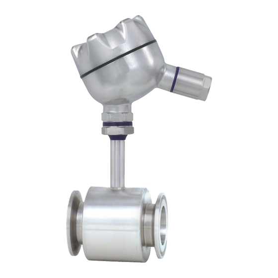
In-line resistance thermometer, Ex i, model TR25
Options: Sealing combination at neck tube, cable gland in hygienic design
®
TYPE EL
CLASS I
JUNE 2018
Operating instructions
Betriebsanleitung
EN
DE
Kapitel
Inhaltsverzeichnis

Verwandte Anleitungen für WIKA TR25


Inhaltszusammenfassung für WIKA TR25
- Seite 33 8. Zusätzliche Hinweise für Geräte mit EHEDG und 3-A 9. Elektrische Anschlusswerte 10. Berechnungsbeispiele für die Eigenerwärmung des Rohrkörpers an der Sensoreinbaustelle 11. Wartung und Reinigung 12. Störungen 13. Demontage, Rücksendung und Entsorgung Anlage: EU-Konformitätserklärung Konformitätserklärungen finden Sie online unter www.wika.de. WIKA Betriebsanleitung Typ TR25 (Ex i)
-
Seite 34: Allgemeines
… weist auf eine möglicherweise gefährliche Situation hin, die zu geringfügigen oder leichten Verletzungen bzw. Sach- und Umweltschäden führen kann, wenn sie nicht gemieden wird. Information … hebt nützliche Tipps und Empfehlungen sowie Informationen für einen effizi- enten und störungsfreien Betrieb hervor. WIKA Betriebsanleitung Typ TR25 (Ex i) -
Seite 35: Sicherheit
Die technischen Spezifikationen in dieser Betriebsanleitung sind einzuhalten. Eine unsachgemäße Handhabung oder ein Betreiben des Gerätes außerhalb der technischen Spezifikationen macht die sofortige Stilllegung und Überprüfung durch einen autorisierten WIKA-Servicemitarbeiter erforderlich. WIKA Betriebsanleitung Typ TR25 (Ex i) -
Seite 36: Personalqualifikation
Festigkeit (Druckstufe) wie der Behälter oder die Rohrleitung aufweisen. Die Schutzrohre bzw. Messgeräte sind nicht für abrasiven Medien geeignet. ■ Den Ein-/Ausbau nur im drucklosen Zustand vornehmen. Vorsicht vor heißen ■ Oberflächen und Restmedien! WIKA Betriebsanleitung Typ TR25 (Ex i) -
Seite 37: Besondere Gefahren
■ Bedarf jederzeit Hilfe zur Stelle ist. dass das Bedienpersonal regelmäßig in allen zutreffenden Fragen von ■ Arbeitssicherheit, Erste-Hilfe und Umweltschutz unterwiesen wird, sowie die Betriebsanleitung und insbesondere die darin enthaltenen Sicherheitshinwei- se kennt. WIKA Betriebsanleitung Typ TR25 (Ex i) - Seite 38 Dieses Gerät nicht in Sicherheits- oder in Not-Aus-Einrichtungen benutzen. Fehlerhafte Anwendungen des Gerätes können zu Verletzungen führen. Am Gerät können im Fehlerfall aggressive Medien mit extremer Temperatur und unter hohem Druck oder Vakuum anliegen. GEFAHR! Auf ausreichende Erdung des Schutzrohres achten. WIKA Betriebsanleitung Typ TR25 (Ex i)
-
Seite 39: Beschilderung, Sicherheitskennzeichnungen Typenschild (Beispiel)
Transmittertyp (nur bei Ausführung mit Transmitter) Angaben zur Ausführung (Meeselement, Ausgangssignal, Messbereich...) Sensor gemäß Norm: F (Dünnfilm-Messwiderstand) Zulassungsrelevante Daten Vor Montage und Inbetriebnahme des Gerätes unbedingt die Betriebs- anleitung lesen! WIKA Betriebsanleitung Typ TR25 (Ex i) -
Seite 40: Technische Daten
Ingenieurpraxis (PED Artikel 4, Absatz 3) ausgelegt und hergestellt. Bei Geräten > DN 25 (1") und der damit verbundenen Kennzeichnung auf dem Messge- ■ rät bzw. Schutzrohr bestätigt WIKA die Konformität mit der Druckgeräterichtlinie nach Konformitätsbewertungsverfahren Modul H. Weitere technische Daten siehe WIKA-Datenblatt TE 60.25 und Bestellunterlagen. -
Seite 41: Aufbau Und Funktion
® PROFIBUS PA zur Verfügung zu stellen. ® 4.2 Abmessungen in mm Ausführung mit Clampanschluss ■ Anschlusskopf Anschlusssockel, Transmitter (Option) Rohrkörper Legende: Halsrohrlänge N (M ) Halslänge Einbaulänge Ø D Rohrinnendurchmesser Ø D Clampstutzen WIKA Betriebsanleitung Typ TR25 (Ex i) - Seite 42 1) Für den maximalen Druckbereich die Druckstufe der Clampklammer beachten. 2) Maximale Betriebstemperatur 150 °C 3) Alle innendruckbeaufschlagte Schutzrohre dieser Typenreihe mit einem Nenndurchmesser (DN) größer 25 mm werden nach Modul H der Druckgeräterichtlinie gefertigt und geprüft. WIKA Betriebsanleitung Typ TR25 (Ex i)
- Seite 43 Rd 65 x 1/6 84 70 40 53 x 1,5 Rd 78 x 1/6 84 70 25 Flanschanschlüsse, Klemmverbindungen und 70 x 2 Rd 95 x 1/6 88 72 25 weitere Nennweiten auf Anfrage. WIKA Betriebsanleitung Typ TR25 (Ex i)
-
Seite 44: Lieferumfang
3. Bei längerer Einlagerung (mehr als 30 Tage) einen Beutel mit Trocknungsmittel der Verpackung beilegen. WARNUNG! Vor der Einlagerung des Gerätes (nach Betrieb) alle anhaftenden Messstoffres- te entfernen. Dies ist besonders wichtig, wenn der Messstoff gesundheitsge- fährdend ist, wie z. B. ätzend, giftig, krebserregend, radioaktiv, usw. WIKA Betriebsanleitung Typ TR25 (Ex i) -
Seite 45: Inbetriebnahme, Betrieb
Betrieb genommen werden, nachdem der Sachverständige festgestellt hat, dass es in den für den Explosionsschutz wesentlichen Merkmalen den Anforderungen entspricht. Außerdem muss der Sachverständige hierfür eine Bescheinigung erstellen und das Betriebsmittel mit einem Prüfzeichen versehen. WIKA Betriebsanleitung Typ TR25 (Ex i) -
Seite 46: Besondere Bedingungen Für Die Verwendung (X-Conditions) Versionen Mit Ø
Bei Verwendung eines Schutzrohres/Halsrohres muss das Gesamtgerät so konstruiert sein, dass ein Einbau in einer Art möglich ist, die zu einem genügend dichten Spalt (IP67) oder einem flammendurchschlagsicheren Spalt (IEC/EN 60079-1) hin zum weniger gefähr- deten Bereich führt. WIKA Betriebsanleitung Typ TR25 (Ex i) -
Seite 47: Ex-Kennzeichnung
1) Die Werte in Klammern gelten für Sonderausführungen. Diese Fühler werden mit besonderen Vergussmassen gefertigt. Weiterhin werden sie mit Gehäusen aus CrNi-Stahl und mit Kabelverschraubungen für den Tieftempera- turbereich ausgestattet Beim Einbau eines Transmitters und/oder einer Digitalanzeige gelten die besonderen Bedingungen aus der Baumusterprüfbescheinigung (siehe Punkt 17). WIKA Betriebsanleitung Typ TR25 (Ex i) - Seite 48 Falls kein Transmitter oder keine Digitalanzeige im Gehäuse montiert ist, findet in diesem auch keine zusätzliche Erwärmung statt. Mit eingebautem Transmitter (optional mit Digital- anzeige) kann eine Erwärmung betriebsbedingt durch den Transmitter oder Digitalanzeige stattfinden. WIKA Betriebsanleitung Typ TR25 (Ex i)
- Seite 49 Die Verwendung eines Betriebsmittels für Anwen- dungen, bei denen eine niedrigere Temperaturklasse (z. B. T2) als die gekennzeichnete gefordert ist, ist zulässig. Hierbei sicherstellen, dass die maximale Umgebungstemperatur für den sicheren Betrieb des Gerätes nicht überschritten wird. WIKA Betriebsanleitung Typ TR25 (Ex i)
-
Seite 50: Maximale Mediumstemperatur
20 mm 50 mm 50 mm 200 °C 100 mm 100 mm > 200 °C ≤ 450 °C WARNUNG! Auch aus Gründen der Arbeitssicherheit und der Ressourcenschonung sollten heiße Oberflächen durch eine Isolierung gegen Berührung und Energieverlust geschützt werden. WIKA Betriebsanleitung Typ TR25 (Ex i) -
Seite 51: Montagebeispiele Im Explosionsgefährdeten Bereichen
Der Fühler samt Gehäuse oder Anschlusskopf befindet sich in Zone 0 (Zone 20). Es ist ein Stromkreis vom Typ Ex ia zu verwenden. Anschlussköpfe/Gehäuse aus Aluminium sind in Zone 0 nicht zulässig. WIKA verwendet an dieser Stelle Anschlussköpfe/Gehäuse aus CrNi-Stahl. - Seite 52 Gewindeanschlüsse oder Rohranschlüsse. Die benutzten Schweißteile, Prozessanschlüsse, Klemmverschraubungen, Schutzrohre oder Gehäuse müssen so ausgelegt sein, dass sie allen durch den Prozess entstehenden Einflüssen wie zum Beispiel Temperatur, Durchflusskräften, Druck, Korrosion, Schwingung und Stößen widerstehen. WIKA Betriebsanleitung Typ TR25 (Ex i)
-
Seite 53: Zusätzliche Hinweise Für Geräte Mit Ehedg Und 3-A
Teile korrosiv angreifen. Temperaturschocks oder schnelle Temperaturänderungen vermeiden. Die Temperatur- ■ differenz zwischen Reinigungsmittel und Klarspülung mit Wasser sollte möglichst gering sein. Negativbeispiel: Reinigung mit 80 °C und Klarspülung mit +4 °C kaltem Wasser. WIKA Betriebsanleitung Typ TR25 (Ex i) -
Seite 54: Elektrische Anschlusswerte
) = Werte siehe „Tabelle 2“ (Spalte 2), Kapitel 7.1.2 “Ex-Kennzeichnung” Die innere Induktivität (L ) und Kapazität (C ) des TR25 sind vernachlässigbar klein. Sensorstromkreis in Zündschutzart Eigensicherheit Ex ia, oder ib, IIC Nur zum Anschluss an eigensichere Stromkreise mit folgenden maximalen Ausgangswer- ten für Geräte der Gerätegruppe II (explosionsfähige Gasatmosphären):... - Seite 55 9.3 Elektrische Daten mit eingebautem Transmitter nach dem FISCO-Modell Die eingesetzten Transmitter/Digitalanzeigen für den Einsatzbereich entsprechend dem FISCO-Modell gelten als FISCO Feldgeräte. Es gelten die Anforderungen nach IEC/EN 60079-27 und die Anschlussbedingungen der Zulassungen gemäß FISCO. WIKA Betriebsanleitung Typ TR25 (Ex i)
-
Seite 56: Berechnungsbeispiele Für Die Eigenerwärmung Des Rohrkörpers An Der Sensoreinbaustelle
10. Berechnungsbeispiele für die Eigenerwärmung des ... 10. Berechnungsbeispiele für die Eigenerwärmung des Rohr- körpers an der Sensoreinbaustelle Rohr-In-Line-Widerstandsthermometer Typ TR25 mit eingebautem Kopftransmitter Typ T32.1S. Die Speisung erfolgt beispielsweise über ein Messumformerspeisegerät Typ KFD2-STC4-EX1 (WIKA-Artikel-Nr. 2341268). ergibt sich aus der Addition der Mediumstemperatur sowie der Eigenerwärmung. Die Eigenerwärmung hängt ab von der zugeführten Leistung P... -
Seite 57: Wartung Und Reinigung
Es wird empfohlen, das Messgerät in regelmäßigen Zeitabständen von ca. 24 Monaten zu rekalibrieren. Dieser Zeitraum verringert sich abhängig vom Einsatzfall. Das Messgerät muss zur Kalibrierung demontiert werden. Die Kalibrierung kann nur durch den Hersteller erfolgen. WIKA Betriebsanleitung Typ TR25 (Ex i) -
Seite 58: Störungen
Gerät unverzüglich außer Betrieb zu setzen, sicherzustellen, dass kein Druck bzw. Signal mehr anliegt und gegen versehentliche Inbetrieb- nahme zu schützen. In diesem Falle Kontakt mit dem Hersteller aufnehmen. Bei notwendiger Rücksendung die Hinweise siehe Kapitel 13.2 „Rücksendung“ beachten. WIKA Betriebsanleitung Typ TR25 (Ex i) -
Seite 59: Demontage, Rücksendung Und Entsorgung
Thermometer nur im drucklosen Zustand demontieren! 13.2 Rücksendung WARNUNG! Beim Versand des Gerätes unbedingt beachten: Alle an WIKA gelieferten Geräte müssen frei von Gefahrstoffen (Säuren, Laugen, Lösungen, etc.) sein. Zur Rücksendung des Gerätes die Originalverpackung oder eine geeignete Transportver- packung verwenden. -
Seite 60: Anlage: Eu-Konformitätserklärung
Anlage: EU-Konformitätserklärung WIKA Betriebsanleitung Typ TR25 (Ex i) - Seite 61 Anlage: EU-Konformitätserklärung WIKA Betriebsanleitung Typ TR25 (Ex i)
- Seite 62 Anlage: EU-Konformitätserklärung WIKA Betriebsanleitung Typ TR25 (Ex i)
- Seite 64 WIKA subsidiaries worldwide can be found online at www.wika.com. WIKA-Niederlassungen weltweit finden Sie online unter www.wika.de. WIKA Alexander Wiegand SE & Co. KG Alexander-Wiegand-Strasse 30 63911 Klingenberg • Germany Tel. +49 9372 132-0 +49 9372 132-406 info@wika.de www.wika.de WIKA operating instructions model TR25 (Ex i)