Herunterladen Inhalt Inhalt Diese Seite drucken

Werbung

Verfügbare Sprachen
  • DE

Verfügbare Sprachen

  • DEUTSCH, seite 27
Copyright Notice:
Copyright Notice:
Copyright Notice:
Copyright Notice:
Copyright Notice:
No part of this installation guide may be reproduced, transcribed, transmitted, or
translated in any language, in any form or by any means, except duplication of
documentation by the purchaser for backup purpose, without written consent of
ASRock Inc.
Products and corporate names appearing in this guide may or may not be registered
trademarks or copyrights of their respective companies, and are used only for
identification or explanation and to the owners' benefit, without intent to infringe.
Disclaimer:
Disclaimer:
Disclaimer:
Disclaimer:
Disclaimer:
Specifications and information contained in this guide are furnished for informational
use only and subject to change without notice, and should not be constructed as a
commitment by ASRock. ASRock assumes no responsibility for any errors or
omissions that may appear in this guide.
With respect to the contents of this guide, ASRock does not provide warranty of any
kind, either expressed or implied, including but not limited to the implied warranties or
conditions of merchantability or fitness for a particular purpose.
In no event shall ASRock, its directors, officers, employees, or agents be liable for
any indirect, special, incidental, or consequential damages (including damages for
loss of profits, loss of business, loss of data, interruption of business and the like),
even if ASRock has been advised of the possibility of such damages arising from any
defect or error in the guide or product.
This device complies with Part 15 of the FCC Rules. Operation is subject to the
following two conditions:
(1) this device may not cause harmful interference, and
(2) this device must accept any interference received, including interference that
may cause undesired operation.
ASRock Website: http://www.asrock.com
Copyright©2004 ASRock INC. All rights reserved.
ASRock K7VT4A Pro Motherboard
Published December 2004
1 1 1 1 1

Werbung

Inhaltsverzeichnis
loading

Inhaltszusammenfassung für ASROCK K7VT4A Pro

  • Seite 1 ASRock. ASRock assumes no responsibility for any errors or omissions that may appear in this guide. With respect to the contents of this guide, ASRock does not provide warranty of any kind, either expressed or implied, including but not limited to the implied warranties or conditions of merchantability or fitness for a particular purpose.
  • Seite 2 Game Port Connector (GAME1) Primary Serial ATA Connector (SATA1) Flash Memory Secondary Serial ATA Connector (SATA2) Shared USB 2.0 Header (JUSB45, Blue) Power LED Connector (PWR_LED1) J1 Jumper (FID0, FID1, FID2, FID3, FID4) 2 2 2 2 2 ASRock K7VT4A Pro Motherboard...
  • Seite 3 2 x USB 2.0 Port (USB2, USB3) Line In (Light Blue) Serial Port: COM1 Line Out (Lime) PS/2 Keyboard Port (Purple) Microphone (Pink) PS/2 Mouse Port (Green) 2 x Shared USB 2.0 Port (USB4, USB5) 3 3 3 3 3 ASRock K7VT4A Pro Motherboard...
  • Seite 4: Package Contents

    Introduction Introduction Introduction Introduction Thank you for purchasing ASRock K7VT4A Pro motherboard, a reliable motherboard produced under ASRock’s consistently stringent quality control. It delivers excellent performance with robust design conforming to ASRock’s commitment to quality and endurance. This Quick Installation Guide contains introduction of the motherboard and step-by- step installation guide.
  • Seite 5: Specifications

    : 1 PS/2 Mouse Port, 1 PS/2 Keyboard Port, 1 Serial Port: COM1, 1 Parallel Port (ECP/EPP Support) 6 ready-to-use USB 2.0 Ports, 1 RJ-45 Port, Audio Jack: Line In / Line Out / Microphone 5 5 5 5 5 ASRock K7VT4A Pro Motherboard...
  • Seite 6 “Manual” in BIOS. See page 9 for the details of “FSB Select Jumpers” adjustment, and page 25 of “User Manual” in the Support CD for “CPU Host Frequency” configuration. 6 6 6 6 6 ASRock K7VT4A Pro Motherboard...
  • Seite 7: Cpu Installation

    CPU. The lever clicks on the side tab to indicate that it is locked. Step 5. Install CPU fan and heatsink. For proper installation, please kindly refer to the instruction manuals of your CPU fan and heatsink vendors. 7 7 7 7 7 ASRock K7VT4A Pro Motherboard...
  • Seite 8 Installation of Memory Modules (DIMM) Installation of Memory Modules (DIMM) Installation of Memory Modules (DIMM) K7VT4A Pro motherboard provides two 184-pin DDR (Double Data Rate) DIMM slots. Please make sure to disconnect power supply before adding or removing DIMMs or the system components.
  • Seite 9: Installing An Expansion Card

    PCI slots: PCI slots are used to install expansion cards that have the 32-bit PCI interface. AGP slot: The AGP slot is used to install a graphics card. The ASRock AGP slot has a special design of clasp that can securely fasten the inserted graphics card.
  • Seite 10 Note: The set of J1 Jumper allows users to adjust the multiplier of CPU. See page 14 of User Manual in the Support CD for details. However, the system will work well without the adjustment of multiplier. You do not have to adjust the multiplier for normal usage. ASRock K7VT4A Pro Motherboard...
  • Seite 11 1.5 Gb/s data transfer rate. Serial ATA (SATA) Either end of the SATA data Data Cable cable can be connected to the SATA hard disk or the SATA connector on the motherboard. ASRock K7VT4A Pro Motherboard...
  • Seite 12 This is an interface for front panel audio cable that allows conve- (9-pin AUDIO1) nient connection and control of (see p.2 item 24) audio devices. System Panel Connector This connector accommodates several system front panel (9-pin PANEL1) functions. (see p.2 item 16) ASRock K7VT4A Pro Motherboard...
  • Seite 13 STEP 2: Connect the SATA power cable to the SATA hard disk. STEP 3: Connect one end of the SATA data cable to the motherboard’s SATA connector. STEP 4: Connect the other end of the SATA data cable to the SATA hard disk. ASRock K7VT4A Pro Motherboard...
  • Seite 14 SATA driver diskette before you start the OS installation. STEP 1: Insert the ASRock Support CD into your optical drive to boot your system. (Do NOT insert any floppy diskette into the floppy drive at this moment!) STEP 2: During POST at the beginning of system boot-up, press <F11>...
  • Seite 15 Main Menu automatically if “AUTORUN” is enabled in your computer. If the Main Menu does not appear automatically, locate and double-click on the file “ASSETUP. EXE” from the “BIN” folder in the Support CD to display the menus. ASRock K7VT4A Pro Motherboard...
  • Seite 16 ASRock K7VT4A Pro Motherboard...
  • Seite 17 ® ® “ ” “ ” “ ” “ ” “ ” “ ” ASRock K7VT4A Pro Motherboard...
  • Seite 18 ASRock K7VT4A Pro Motherboard...
  • Seite 19 ASRock K7VT4A Pro Motherboard...
  • Seite 20 “ ” ASRock K7VT4A Pro Motherboard...
  • Seite 21 ASRock K7VT4A Pro Motherboard...
  • Seite 22 “ ” SATA1 SATA2 ASRock K7VT4A Pro Motherboard...
  • Seite 23 AUX1 ASRock K7VT4A Pro Motherboard...
  • Seite 24 ASRock K7VT4A Pro Motherboard...
  • Seite 25 ASRock K7VT4A Pro Motherboard...
  • Seite 26 ® ® ASRock K7VT4A Pro Motherboard...
  • Seite 27 1. Einführung 1. Einführung 1. Einführung Wir danken Ihnen für den Kauf des ASRock K7VT4A Pro Motherboard, ein zuverlässiges Produkt, welches unter den ständigen, strengen Qualitätskontrollen von ASRock gefertigt wurde. Es bietet Ihnen exzellente Leistung und robustes Design, gemäß der Verpflichtung von ASRock zu Qualität und Halbarkeit.
  • Seite 28: Spezifikationen

    5.1 Kanal AC’97 Audio LAN: Speed: 802.3u (10/100 Ethernet), unterstützt Wake-On-LAN Hardware Monitor: Überwachung der CPU-Temperatur Motherboardtemperaturerkennung CPU-Überhitzungsschutz durch rechtzeitigen Systemshutdown (ASRock U-COP)(Siehe VORSICHT 1) Drehzahlmessung für CPU-Lüfter Drehzahlmessung für Gehäuselüfter Spannungsüberwachung: +12V, +5V, +3.3V, Vcore PCI-Slots: 5 slots nach PCI-Spezifikation 2.2 AGP-Slot: 1 AGP-Slot, unterstützt 1.5V, 8X/4X AGP-Karten...
  • Seite 29 FSB-Auswahljumper entsprechend der FSB Ihrer AMD CPU einstellen, bevor Sie “CPU Host Frequency” im BIOS auf “Manual” (Manuell) einstellen. Siehe Seite 33 für detaillierte Anweisungen zur Einstellung des FSB-Auswahljumpers und Seite 25 im Benutzerhandbuch auf der Support CD für die CPU Host-Frequenz-Konfiguration. ASRock K7VT4A Pro Motherboard...
  • Seite 30: Sicherheitshinweise Vor Der Montage

    Schritt 5: Installieren Sie einen aktiven CPU-Kühler, der die gesamte Fläche der CPU abdeckt und eine ausreichende Wärmeableitung für den von Ihnen verwendeten CPU-Typ bietet. Weitere Hinweise finden Sie der Installationsanleitung für Ihren CPU-Kühler. ASRock K7VT4A Pro Motherboard...
  • Seite 31: Installation Der Speichermodule (Dimm)

    2.2 Installation der Speichermodule (DIMM) 2.2 Installation der Speichermodule (DIMM) 2.2 Installation der Speichermodule (DIMM) Das K7VT4A Pro-Motherboard hat zwei 184-pol. DDR- (Double Data Rate) DIMM- Steckplätze. Achten Sie darauf, das Netzteil abzustecken, bevor Sie DIMMs oder Systemkomponenten hinzufügen oder entfernen.
  • Seite 32: Einbau Einer Erweiterungskarte

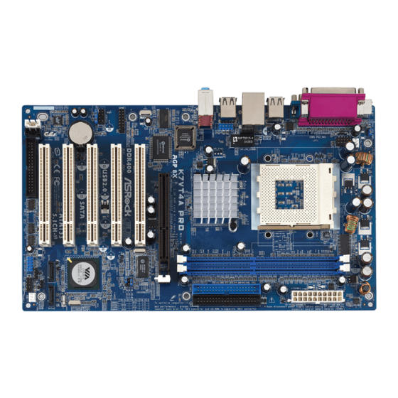
    (PCI- und AGP GP-Slots): -Slots): -Slots): Es gibt 5 PCI-Steckplätze und 1 AGP-Steckplatz auf dem K7VT4A Pro Motherboard. PCI-Slots: PCI-Slots werden zur Installation von Erweiterungskarten mit dem 32bit PCI-Interface genutzt. AGP-Slot: Der AGP-Steckplatz dient zur Installation einer Grafikkarte. Der ASRock AGP-Steckplatz hat speziell entwickelte Klammern, die die eingefügte...
  • Seite 33: Einstellung Der Jumper

    Hinweis: Um +5VSB nutzen zu können, muss das Netzteil auf dieser Leitung 2A oder mehr leisten können. JR1- / JL1-Jumper (siehe S.2, Punkt 23) Hinweis: Wenn die JR1- und JL1- Jumper verbunden sind, können die Audioanschlüsse an dem Frontfeld sowie an der Rückwand arbeiten. ASRock K7VT4A Pro Motherboard...
  • Seite 34 Hinweis: Die Einstellung des J1-Jumpers legt den Multiplikator der CPU-Frequenz fest. Siehe Seite 14 im Benutzerhandbuch auf der Support CD für Details. Ohne Einstellung des Multiplikators wird das System auch eine gute Arbeit leisten. Normalerweise müssen Sie die Einstellung des Multiplikators nicht vornehmen. ASRock K7VT4A Pro Motherboard...
  • Seite 35 CD-ROM mit dem sekundären IDE-Anschluss (IDE2, schwarz). Seriell-ATA-Anschlüsse Diese beiden Serial ATA- (SATA-)Verbínder (SATA1: siehe S.2, Punkt 12) SATA1 SATA2 unterstützten SATA-Datenkabel (SATA2: siehe S.2, Punkt 13) für interne Massenspeichergeräte. Die aktuelle SATA-Schnittstelle ermöglicht eine Datenübertragungsrate bis 1,5 Gb/s. ASRock K7VT4A Pro Motherboard...
  • Seite 36 ASRock I/O Plus™ (9-pin JUSB45) gemeinsam genutzt. Bei (siehe S.2, Punkt 28) Verwendung der vorderseitigen USB- Anschlüsse durch Verbinden des vorseitigen USB-Kabels mit diesem Header (JUSB45) werden die USB-Anschlüsse 4,5 auf ASRock I/O Plus™ nicht funktionieren. ASRock K7VT4A Pro Motherboard...
  • Seite 37 Verbinden Sie das CPU - Lüfterkabel mit diesem (3-pin CPU_FAN1) Anschluss und passen Sie den (siehe S.2, Punkt 2) schwarzen Draht dem Erdungsstift an. ATX-Netz-Header Verbinden Sie die ATX- Stromversorgung mit diesem (20-pin ATXPWR1) Header. (siehe S.2, Punkt 6) ASRock K7VT4A Pro Motherboard...
  • Seite 38 SCHRITT 2: Verbinden Sie das SATA-Netzkabel mit der SATA-Festplatte. SCHRITT 3: Schließen Sie ein Ende des SATA-Datenkabels am SATA-Anschluss des Motherboards an. SCHRITT 4: Schließen Sie das andere Ende des SATA-Datenkabels an die SATA- Festplatte an. ASRock K7VT4A Pro Motherboard...
  • Seite 39 Sie eine SATA-Treiberdiskette, bevor Sie mit der Installation des Betriebssystems beginnen. SCHRITT 1: Legen Sie die ASRock Support-CD in Ihr optisches Laufwerk, um Ihr System hochzufahren. (Legen Sie zu diesem Zeitpunkt KEINE Diskette in das Diskettenlaufwerk ein!) SCHRITT 2: Während des Selbsttests zu Beginn des Systemstarts drücken Sie...
  • Seite 40 Sie können die RAID-Konfiguration auch mit “VIA RAID Tool” in einer Windows- Umgebung einstellen. Beziehen Sie sich auf das Dokument “Anleitung für VIA RAID Tool” auf der Support-CD, das sich im Ordner des folgendes Pfades befindet: .. \ VIA RAID Tool ASRock K7VT4A Pro Motherboard...
  • Seite 41 ASSETUP.EXE im BIN-Verzeichnis der Support-CD, um die Menüs aufzurufen. Das Setup-Programm soll es Ihnen so leicht wie möglich machen. Es ist menügesteuert, d.h. Sie können in den verschiedenen Untermenüs Ihre Auswahl treffen und die Programme werden dann automatisch installiert. ASRock K7VT4A Pro Motherboard...
  • Seite 42 1. Introduction 1. Introduction Merci pour votre achat d’une carte mère ASRock K7VT4A Pro, une carte mère très fiable produite selon les critères de qualité rigoureux de ASRock. Elle offre des performances excellentes et une conception robuste conformément à l’engagement d’ASRock sur la qualité...
  • Seite 43 Mesure de température de la carte mère Coupure du CPU en cas de surchauffe afin de protéger la durée de vie du CPU (ASRock U-COP)(voir ATTENTION 1) Tachéomètre ventilateur CPU; Tachéomètre ventilateur châssis Monitoring de la tension: +12V, +5V, +3.3V, Vcore Slots PCI: 5 slots PCI spécification 2.2...
  • Seite 44 “Fréquence hôte processeur” sur “Manuel” dans le BIOS. Voir la page 48 pour les détails sur les réglages des “Cavaliers de sélection de bus frontal”, et la page 25 du “Manuel de l’utilisateur” sur le CD d’assistance pour la configuration de la “Fréquence hôte de processeur”. ASRock K7VT4A Pro Motherboard...
  • Seite 45 CPU. Le verrouillage du levier dans son encoche latérale est annoncé par un clic. Etape 5. Installez le ventilateur et le radiateur du CPU. Pour une installation correcte, reportez-vous aux manuels du fabricant du ventilateur et du radiateur de CPU. ASRock K7VT4A Pro Motherboard...
  • Seite 46 2.2 Installation des modules mémoire (DIMM) 2.2 Installation des modules mémoire (DIMM) 2.2 Installation des modules mémoire (DIMM) La carte mère K7VT4A Pro propose deux emplacements DIMM DDR (Double Débit de données) à 184 broches. Ayez bien le soin de débrancher l’alimentation avant d’ajouter ou de retirer des modules DIMM ou les composants du système.
  • Seite 47 2.3 Slot d’extension (Slots PCI et Slot AGP) 2.3 Slot d’extension (Slots PCI et Slot AGP) Il y a 5 emplacements PCI et 1 emplacement AGP sur la carte mère K7VT4A Pro. Slots PCI: Les slots PCI sont utilisés pour installer des cartes d’extension dotées d’une interface PCI 32 bits.
  • Seite 48 Note: Pour sélectionner +5VSB, il faut obligatoirement 2 Amp et un courant standby supérieur fourni par l’alimentation. Cavaliers JR1 / JL1 (voir p.2 fig. 23) Note: Si les cavaliers JR1 et JL1 sont en court-circuit, les connecteurs audio des panneaux avant et arrière peuvent fonctionner. ASRock K7VT4A Pro Motherboard...
  • Seite 49 Voir la page 14 du manuel de l’utilisateur sur le CD d’assistance pour les détails. Toutefois, le système fonctionnera correctement sans réglage du multiplieur. Vous n’avez pas besoin d’ajuster le multiplieur dans le cadre de l’utilisation normale. ASRock K7VT4A Pro Motherboard...
  • Seite 50 (SATA1: voir p.2 fig. 12) SATA1 SATA2 charge les câbles SATA pour (SATA2: voir p.2 fig. 13) les périphériques de stockage internes. L’interface SATA actuelle permet des taux transferts de données pouvant aller jusqu’à 1,5 Go/s. ASRock K7VT4A Pro Motherboard...
  • Seite 51 En-tête USB 2.0 partagé Cet en-tête USB45 est partagé avec les ports USB 2.0 (JUSB45 br.9) 4 et 5 sur ASRock I/O Plus™. (voir p.2 fig. 28) Lorsque vous utilisez les ports USB du panneau frontal en connectant le câble USB du panneau frontal à...
  • Seite 52 Veuillez connecter une unité d’alimentation ATX sur ce (ATXPWR1 br. 20) connecteur. (voir p.2 fig. 6) Connecteur de l’indicateur Veuillez connecter un câble d’alimentation pour indicateur d’alimentation 3 broches sur connecteur. (PWR_LED1 br. 3) (voir p.2 fig. 14) ASRock K7VT4A Pro Motherboard...
  • Seite 53 ETAPE 2 : Connectez le câble d’alimentation SATA au disque dur SATA. ETAPE 3 : Connectez l’une des extrémités du câble de données SATA sur le connecteur SATA de la carte mère. ETAPE 4 : Connectez l’autre extrémité du câble de données SATA au disque dur SATA. ASRock K7VT4A Pro Motherboard...
  • Seite 54 SATA, vous devez créer une disquette de pilotage SATA avant de lancer l’installation du système d’exploitation. ETAPE 1 : Insérez le CD de soutien ASRock dans votre lecteur de disque optique pour démarrer votre système. (N’insérez AUCUNE disquette dans le lecteur de disquette pour l’instant!)
  • Seite 55 Vous pouvez également régler la configuration RAID en utilisant le “VIA RAID Tool” dans l’environnement Windows. Veuillez vous référer au document contenu sur le CD de support, “Guide d’utilisation de le VIA RAID Tool”, qui se trouve dans le dossier ci- dessous : .. \ VIA RAID Tool ASRock K7VT4A Pro Motherboard...
  • Seite 56 “AUTORUN” est activé dans votre ordinateur. Si le Menu principal n’apparaît pas automatiquement, localisez dans le CD technique le fichier ASSETUP.EXE dans le dossier BIN et double-cliquez dessus pour afficher les menus. ASRock K7VT4A Pro Motherboard...
  • Seite 57 1. Introduzione Grazie per aver scelto una scheda madre ASRock K7VT4A Pro, una scheda madre affidabile prodotta secondo i severi criteri di qualità ASRock. Le prestazioni eccellenti e il design robusto si conformano all’impegno di ASRock nella ricerca della qualità e della resistenza.
  • Seite 58 Sensore per la temperatura del processore Sensore temperatura scheda madre Chiusura automatica del processore in caso di surriscaldamento per proteggere la CPU (ASRock U-COP)(vedi ATTENZIONE 1) Indicatore di velocità per la ventola del processore Indicatore di velocità per la ventola di raffreddamento Voltaggio: +12V, +5V, +3.3V, Vcore...
  • Seite 59 CPU AMD prima di impostare la configurazione della “Frequenza Host della CPU” su “Manuale” nel BIOS. Si veda pagina 63 per avere maggiori informazioni sulla regolazione “Selezione Jumper FSB”, e pagina 25 del “Manuale utente” nel CD per la configurazione della “Frequenza Host della CPU”. ASRock K7VT4A Pro Motherboard...
  • Seite 60: Installazione

    Quando la leva fa clic sulla linguetta laterale significa che è bloccata. Step 5. Installare la ventola del processore e l’heatsink. Per una corretta installazione, per favore fare riferimento ai manuali di istruzione dei produttori della ventola e dell’heatsink del processore. ASRock K7VT4A Pro Motherboard...
  • Seite 61 2.2 Installazione dei moduli di memoria (DIMM) 2.2 Installazione dei moduli di memoria (DIMM) La motherboard K7VT4A Pro mette a disposizione due slot DIMM DDR (Double Data Rate) da 184 pin. Scollegare l’alimentazione elettrica prima di aggiungere o rimuovere i DIMM o altri componenti del sistema.
  • Seite 62 2.3 Slot di espansione (PCI e slot AGP) 2.3 Slot di espansione (PCI e slot AGP) La motherboard K7VT4A Pro dispone di cinque slot PCI e uno slot AGP. Slot PCI: Sono utilizzati per installare schede di espansione con Interfaccia PCI a 32-bit.
  • Seite 63 Nota: Per selezionare +5VSB, si richiedono almeno 2 Ampere e il consumo di corrente in standby sarà maggiore. Jumper JR1 / JL1 (vedi p.2 item 23) Nota: Se i jumper JR1 e JL1 sono in corto, possono funzionare i connettori audio del pannello frontale e del pannello posteriore. ASRock K7VT4A Pro Motherboard...
  • Seite 64 CPU. Si veda pagina 14 del Manuale utente nel CD per avere maggiori informazioni. Tuttavia, il sistema funziona correttamente anche senza la regolazione del moltiplicatore. Il moltiplicatore non deve essere regolato per il funzionamento normale. ASRock K7VT4A Pro Motherboard...
  • Seite 65 SATA1 SATA2 dati SATA per dispositivi di (SATA2: vedi p.2 item 13) immagazzinamento interni. ATA (SATA) supportano cavi SATA per dispositivi di memoria interni. L’interfaccia SATA attuale permette velocità di trasferimento dati fino a 1.5 Gb/s. ASRock K7VT4A Pro Motherboard...
  • Seite 66 Collettore USB 2.0 Questo collettore USB45 è condiviso condiviso con le porte USB 2.0 4 e 5 su ASRock I/O Plus™. (9-pin JUSB45) Quando si utilizzano le porte (vedi p.2 item 28) USB del pannello frontale, attaccando il cavo USB...
  • Seite 67 Collegare la sorgente d’alimentazione ATX a questo (20-pin ATXPWR1) collettore. (vedi p.2 item 6) Connettore del LED di Collegare il cavo del LED di accensione accensione a 3 pin a questo connettore. (3-pin PWR_LED1) (vedi p.2 item 14) ASRock K7VT4A Pro Motherboard...
  • Seite 68 SAT T T T T A A A A A dischi rigidi SA dischi rigidi SA dischi rigidi SA La scheda madre K7VT4A Pro supporta la funzione di collegamento e scambio a caldo per i dispositivi SATA. NOTA Che cosa è la funzione di collegamento a caldo? Se i dischi rigidi SATA NON sono impostati per una configurazione RAID, è...
  • Seite 69 Se si vuole installare Windows 2000 o Windows XP sui dischi rigidi SATA, è necessario creare un dischetto driver SATA prima di iniziare l’installazione del sistema operativo. 1° PASSO: Inserire il CD di supporto ASRock nel lettore ottico prima di accendere il sistema. (NON inserire nessun dischetto floppy nel drive in questo momento!) 2°...
  • Seite 70 Inserire il CD di supporto nel lettore CD-ROM. Se la funzione “AUTORUN” è attivata nel computer, apparirà automaticamente il Menù principale. Se il Menù principale non appare automaticamente, posizionarsi sul file ASSETUP. EXE nel CESTINO del CD di supporto e cliccare due volte per visualizzare i menù. ASRock K7VT4A Pro Motherboard...
  • Seite 71 1. Introducción 1. Introducción Gracias por su compra de ASRock K7VT4A Pro placa madre, una placa de confianza producida bajo el control de calidad estricto y persistente. La placa madre provee realización excelente con un diseño robusto conforme al compromiso de calidad y resistencia de ASRock.
  • Seite 72 : 1 puerto de ratón PS/2, 1 puerto de teclado PS/2, 1 puerto serial: COM 1, 1 puerto paralelo: soporta ECP/EPP, 6 puertos USB 2.0 predeterminados, 1 puerto RJ-45, Audio Jack: Line In / Line Out / Micrófono ASRock K7VT4A Pro Motherboard...
  • Seite 73 “FSB Select Jumpers” (Jumpers de selección de FSB) y la página 25 del “User Manual” (Manual del usuario) en el CD de soporte para obtener información sobre la configuración de “CPU Host Frequency” (Frecuencia de host de CPU). ASRock K7VT4A Pro Motherboard...
  • Seite 74 CPU, examine su orientación o examine si los pins están ya encorvados. Paso 4. Encierre el zócalo bajando la palanca. Paso 5. Instale el disipador de calor con ventilador del CPU ( consulte la documentación del disipador de calor). ASRock K7VT4A Pro Motherboard...
  • Seite 75 2.2 Instalación de Memoria 2.2 Instalación de Memoria 2.2 Instalación de Memoria La placa base K7VT4A Pro proporciona dos zócalos DIMM DDR (Doble velocidad de datos) de 184 contactos Asegúrese de desconectar la fuente de alimentación antes de añadir o retirar módulos DIMM o componentes del sistema.
  • Seite 76 2.3 Ranuras de Expansión (Ranuras PCI y AGP ) 2.3 Ranuras de Expansión (Ranuras PCI y AGP ) En la placa base K7VT4A Pro hay 5 ranuras PCI y 1 AGP. Ranura PCI: Para instalar tarjetas de expansión que tienen 32-bit Interface PCI.
  • Seite 77 Atención: Para elegir +5VSB, se necesita corriente mas que 2 Amp proveida por la fuente de electricidad. Jumpers JR1 / JL1 (vea p.2, No. 23) Atención: Si los jumpers JR1 y JL1 son cortos, los conectores de audio del panel frontal y los del panel posterior podrán funcionar. ASRock K7VT4A Pro Motherboard...
  • Seite 78 CPU. Consulte la página 14 del manual del usuario en el CD de soporte para obtener información más detallada. En cualquier caso, el sistema funcionará bien sin ajustar el multiplicador. No es necesario que ajuste el multiplicador para un uso normal. ASRock K7VT4A Pro Motherboard...
  • Seite 79 La interfaz SATA actual permite una velocidad de transferencia de 1.5 Gb/s. Cable de datos de Ambos extremos del cable serie ATA (SATA) pueden conectarse al disco duro SATA o la conexión de la placa base. ASRock K7VT4A Pro Motherboard...
  • Seite 80 USB del panel (vea p.2, No. 28) frontal conectando el cable USB del panel frontal a este cabezal (JUSB45), los puertos USB 4 y 5 en el ASRock I/O Plus no funcionarán. Conector de Audio Interno Permite recepción de input audio de fuente sónica como...
  • Seite 81 (3-pin PWR_LED1) encendido en esta conexión. (vea p.2, No. 14) Conexión de juegos Conecte un cable de juegos a esta conexión si se instala el (15-pin GAME1) soporte del puerto de juegos. (vea p.2, No. 26) ASRock K7VT4A Pro Motherboard...
  • Seite 82: Configuración Raid

    HDDs SAT T T T T A A A A A HDDs SA HDDs SA HDDs SA La placa base K7VT4A Pro soporta la función de conexión en caliente para Dispositivos SATA. NOTA ¿Qué es la función de conexión en caliente? Si los HDDs SATA no están fijados para su configuración RAID, se...
  • Seite 83 SATA antes de iniciar la instalación del SO. PASO 1: Inserte el CD de soporte de ASRock en la unidad óptica de la unidad para iniciar el sistema. (NO inserte ningún disquete en la unidad de disco en este momento) PASO 2: Durante la comprobación inicial (POST) del sistema, pulse la tecla <F11>...
  • Seite 84 Para iniciar la instalación, ponga el CD en el lector de CD y se desplegará el Menú Principal automáticamente si «AUTORUN» está habilitado en su computadora. Si el Menú Principal no aparece automáticamente, localice y doble-pulse en el archivo ASSETUP.EXE para iniciar la instalación. ASRock K7VT4A Pro Motherboard...

Inhaltsverzeichnis