Herunterladen Inhalt Inhalt Diese Seite drucken

Werbung

Verfügbare Sprachen
  • DE

Verfügbare Sprachen

  • DEUTSCH, seite 26
Copyright Notice:
Copyright Notice:
Copyright Notice:
Copyright Notice:
Copyright Notice:
No part of this installation guide may be reproduced, transcribed, transmitted, or
translated in any language, in any form or by any means, except duplication of
documentation by the purchaser for backup purpose, without written consent of
ASRock Inc.
Products and corporate names appearing in this guide may or may not be registered
trademarks or copyrights of their respective companies, and are used only for
identification or explanation and to the owners' benefit, without intent to infringe.
Disclaimer:
Disclaimer:
Disclaimer:
Disclaimer:
Disclaimer:
Specifications and information contained in this guide are furnished for informational
use only and subject to change without notice, and should not be constructed as a
commitment by ASRock. ASRock assumes no responsibility for any errors or
omissions that may appear in this guide.
With respect to the contents of this guide, ASRock does not provide warranty of any
kind, either expressed or implied, including but not limited to the implied warranties or
conditions of merchantability or fitness for a particular purpose.
In no event shall ASRock, its directors, officers, employees, or agents be liable for
any indirect, special, incidental, or consequential damages (including damages for
loss of profits, loss of business, loss of data, interruption of business and the like),
even if ASRock has been advised of the possibility of such damages arising from
any defect or error in the guide or product.
ASRock Website: http://www.asrock.com
Copyright©2003 ASRock INC. All rights reserved.
ASRock K7S41 / K7S41GX Motherboard
Published December 2003
1 1 1 1 1

Werbung

Inhaltsverzeichnis
loading

Inhaltszusammenfassung für ASROCK K7S41

  • Seite 1 ASRock. ASRock assumes no responsibility for any errors or omissions that may appear in this guide. With respect to the contents of this guide, ASRock does not provide warranty of any kind, either expressed or implied, including but not limited to the implied warranties or conditions of merchantability or fitness for a particular purpose.
  • Seite 2 (FSB_SEL0/FSB_SEL1/FSB_SEL2) Chassis Fan Connector Internal Audio Connector: CD1 (CHA_FAN1) (Black) Power LED Connector Internal Audio Connector: AUX1 (PWR_LED1) (White) System Panel Connector FID Jumpers (PANEL1) (FID0, FID1, FID2, FID3, FID4) 2 2 2 2 2 ASRock K7S41 / K7S41GX Motherboard...
  • Seite 3 (FSB_SEL0/FSB_SEL1) Chassis Fan Connector Internal Audio Connector: CD1 (CHA_FAN1) (Black) Power LED Connector Internal Audio Connector: AUX1 (PWR_LED1) (White) System Panel Connector FID Jumpers (PANEL1) (FID0, FID1, FID2, FID3, FID4) 3 3 3 3 3 ASRock K7S41 / K7S41GX Motherboard...
  • Seite 4 (K7S41 / K7S41GX) Parallel Port Line Out (Lime) RJ-45 Port USB 2.0 Ports Game Port VGA Port Microphone (Pink) PS/2 Keyboard Port (Purple) Line In (Light Blue) PS/2 Mouse Port (Green) 4 4 4 4 4 ASRock K7S41 / K7S41GX Motherboard...
  • Seite 5: Package Contents

    1. Introduction 1. Introduction 1. Introduction Thank you for purchasing ASRock K7S41 / K7S41GX motherboard, a reliable motherboard produced under ASRock’s consistently stringent quality control. It delivers excellent performance with robust design conforming to ASRock’s com- mitment to quality and endurance.
  • Seite 6 2 slots with PCI Specification 2.2 AGP slot: 1 AGP slot, supports 1.5V, 8X/4X AGP card (see CAUTION 2) AMR slot: 1 slot, supports ASRock MR card (Optional) USB 2.0: 6 USB 2.0 ports: includes 4 default USB 2.0 ports on the rear panel, plus one connector to support 2 additional USB 2.0 ports...
  • Seite 7 “Manual” option as the FSB setting in BIOS setup to perform over clocking. Please check page 24 of the User Manual in the Support CD for details. 7 7 7 7 7 ASRock K7S41 / K7S41GX Motherboard...
  • Seite 8: Cpu Installation

    Step 5. Install CPU fan and heatsink. For proper installation, please kindly refer to the instruction manuals of your CPU fan and heatsink vendors. 8 8 8 8 8 ASRock K7S41 / K7S41GX Motherboard...
  • Seite 9 2.2 Installation of Memory Modules (DIMM) 2.2 Installation of Memory Modules (DIMM) 2.2 Installation of Memory Modules (DIMM) K7S41 / K7S41GX motherboard provides two 184-pin DDR (Double Data Rate) DIMM slots. Please make sure to disconnect power supply before adding or removing DIMMs or the system components.
  • Seite 10: Installing An Expansion Card

    2.3 Expansion Slots (PCI, AMR, and AGP Slots) There are 2 PCI slots, 1 AMR slot, and 1 AGP slot on K7S41 / K7S41GX motherboard. PCI slots: PCI slots are used to install expansion cards that have the 32-bit PCI interface.
  • Seite 11 Note: To select +5VSB, it requires 2 Amp and higher standby current provided by power supply. (see p.2/p.3 No. 24) (see p.2/p.3 No. 23) Note: If the jumpers JL1 and JR1 are short (see the figure above), both front panel and rear panel audio connectors can work. ASRock K7S41 / K7S41GX Motherboard...
  • Seite 12 Connector Figure Description FDD Connector (33-pin FLOPPY1) (see p.2/p.3 No. 17) the red-striped side to Pin1 Note: Make sure the red-striped side of the cable is plugged into Pin1 side of the connector. ASRock K7S41 / K7S41GX Motherboard...
  • Seite 13 (AUX1: see p.2/p.3 No. 29) or MPEG card. Front Panel Audio Connector This is an interface for front panel audio cable that allows conve- (9-pin AUDIO1) nient connection and control of (see p.2/p.3 No. 25) audio devices. ASRock K7S41 / K7S41GX Motherboard...
  • Seite 14 Serial port connector This COM1 connector supports a serial port module. (9-pin COM1) (see p.2/p.3 No. 22) Power LED Connector Please connect a 3-pin power LED cable to this connector. (3-pin PWR_LED1) (see p.2/p.3 No. 14) ASRock K7S41 / K7S41GX Motherboard...
  • Seite 15 EXE from the BIN folder in the Support CD to display the menus. “PC-DIY Live Demo” ASRock presents you a multimedia PC-DIY live demo, which shows you how to install your own PC system step by step. To see this demo program, ®...
  • Seite 16 ASRock K7S41 / K7S41GX Motherboard...
  • Seite 17 ASRock K7S41 / K7S41GX Motherboard...
  • Seite 18 ® ® ASRock K7S41 / K7S41GX Motherboard...
  • Seite 19 ° ASRock K7S41 / K7S41GX Motherboard...
  • Seite 20 ASRock K7S41 / K7S41GX Motherboard...
  • Seite 21 ASRock K7S41 / K7S41GX Motherboard...
  • Seite 22 ” ” ASRock K7S41 / K7S41GX Motherboard...
  • Seite 23 “ ” AUX1 ASRock K7S41 / K7S41GX Motherboard...
  • Seite 24 ASRock K7S41 / K7S41GX Motherboard...
  • Seite 25 ® ® “PC-DIY Live Demo” ASRock “PC-DIY Live Demo” ® ® Microsoft Media Player ..\ MPEGAV \ AVSEQ01.DAT ASRock K7S41 / K7S41GX Motherboard...
  • Seite 26: Einführung

    1. Einführung 1. Einführung 1. Einführung Wir danken Ihnen für den Kauf des ASRock K7S41 / K7S41GX Motherboard, ein zuverlässiges Produkt, welches unter den ständigen, strengen Qualitätskontrollen von ASRock gefertigt wurde. Es bietet Ihnen exzellente Leistung und robustes Design, gemäß der Verpflichtung von ASRock zu Qualität und Halbarkeit.
  • Seite 27: Spezifikationen

    1 AGP-Slot, unterstützt 1.5V, 8X/4X AGP-Karten (siehe VORSICHT 2) AMR-Slot: Unterstützt ASRock MR-Karten (Option) USB 2.0: 6 USB 2.0-Anschlüsse: einschließlich 4 Standard-USB 2.0-Anschlüsse auf der Rückseite, plus einem Header zur Unterstützung 2 zusätzlicher USB 2.0-Anschlüsse (siehe VORSICHT 3) ASRock K7S41 / K7S41GX Motherboard...
  • Seite 28 Motherboards entscheidet die Jumper-Einstellung. Sie müssen den FSB- Jumper gemäß Ihrer AMD-CPU setzen, bevor Sie mit der Option “Manual” als FSB-Einstellung im BIOS-Setup Overclocking ausführen. Details hierzu siehe Seite 24 der Bedienungsanleitung auf der Support-CD. ASRock K7S41 / K7S41GX Motherboard...
  • Seite 29: Sicherheitshinweise Vor Der Montage

    Schritt 5: Installieren Sie einen aktiven CPU-Kühler, der die gesamte Fläche der CPU abdeckt und eine ausreichende Wärmeableitung für den von Ihnen verwendeten CPU-Typ bietet. Weitere Hinweise finden Sie der Installationsanleitung für Ihren CPU-Kühler. ASRock K7S41 / K7S41GX Motherboard...
  • Seite 30: Installation Der Speichermodule (Dimm)

    2.2 Installation der Speichermodule (DIMM) 2.2 Installation der Speichermodule (DIMM) 2.2 Installation der Speichermodule (DIMM) Das K7S41 / K7S41GX-Motherboard hat zwei 184-pol. DDR- (Double Data Rate) DIMM-Steckplätze. Achten Sie darauf, das Netzteil abzustecken, bevor Sie DIMMs oder Systemkomponenten hinzufügen oder entfernen.
  • Seite 31: Einbau Einer Erweiterungskarte

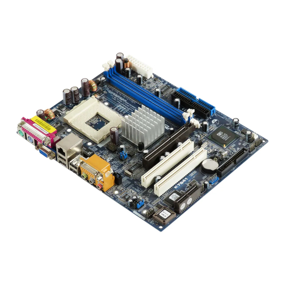
    -, und AGP GP-Slots): -Slots): -Slots): Es gibt 3 PCI-, 1 AMR-, und 1 AGP-Slot auf dem K7S41 / K7S41GX-Motherboard. PCI-Slots: PCI-Slots werden zur Installation von Erweiterungskarten mit dem 32bit PCI-Interface genutzt. AMR-Slot: Der AMR-Steckplatz dient zur Aufnahme der ASRock MR-Karte (Option) mit v.92 Modem-Funktionalität.
  • Seite 32: Einstellung Der Jumper

    Hinweis: Um +5VSB nutzen zu können, muss das Netzteil auf dieser Leitung 2A oder mehr leisten können. (siehe S.2/S.3, Punkt 24) (siehe S.2/S.3, Punkt 23) Hinweis: Sind die Jumper JL1 und JR1 kurzgeschlossen (siehe obige Abbildung), funktionieren die Audioanschlüsse auf der Vorderseite und der Rückseite. ASRock K7S41 / K7S41GX Motherboard...
  • Seite 33: Anschlüsse

    Anschluss für das Floppy-Laufwerk (33-Pin FLOPPY1) die rotgestreifte Seite auf Stift 1 (siehe S.2/S.3, Punkt 17) Hinweis: Achten Sie darauf, dass die rotgestreifte Seite des Kabel mit der Stift 1- Seite des Anschlusses verbunden wird. ASRock K7S41 / K7S41GX Motherboard...
  • Seite 34 (AUX1: siehe S.2/S.3, Punkt 28) zu verbinden. Anschluss für Audio auf Dieses Interface zu einem der Gehäusevorderseite Audio-Panel auf der Vorderseite Ihres Gehäuses, ermöglicht (9-Pin AUDIO1) Ihnen eine bequeme (siehe S.2/S.3, Punkt 25) Kontrolle über Audio-Geräte. ASRock K7S41 / K7S41GX Motherboard...
  • Seite 35 Diese Anschlussleiste für COM1 unterstützt ein serielles (9-pin COM1) Port-Modul. (siehe S.2/S.3 - Punkt 22) Anschluss für Verbinden Sie ein 3-pin. Kabel Betriebsanzeige (LED) der Betriebsanzeige (LED) mit diesem Anschluss. (3-pin PWR_LED1) (siehe S.2/S.3, Punkt 14) ASRock K7S41 / K7S41GX Motherboard...
  • Seite 36 Sie können in den verschiedenen Untermenüs Ihre Auswahl treffen und die Programme werden dann automatisch installiert. “PC-DIY Live Demo” ASRock präsentiert Ihnen eine Multimedia PC-DIY Live Demo, die Ihnen verdeutlicht, wie man Schritt für Schritt ein eigenes PC-System montiert. ®...
  • Seite 37 1. Introduction 1. Introduction Merci pour votre achat d’une carte mère ASRock K7S41 / K7S41GX, une carte mère très fiable produite selon les critères de qualité rigoureux de ASRock. Elle offre des performances excellentes et une conception robuste conformément à l’engagement d’ASRock sur la qualité...
  • Seite 38 Contrôle de la température du châssis, Coupure du CPU en cas de surchauffe afin de protéger la durée de vie du CPU (ASRock U-COP)(voir ATTENTION 1), Tachéomètre ventilateur CPU, Tachéomètre ventilateur châssis, Monitoring de la tension: +12V, +5V, +3V, Vcore Slots PCI: 2 slots PCI spécification 2.2...
  • Seite 39 FSB en fonction de votre UC AMD avant d’utiliser l’option “Manuel” comme réglage FSB dans la Configuration BIOS pour appliquer un over clocking. Veuillez consulter la page 24 du Manuel de l’utilisateur dans le CD d’assistance plus de détails. ASRock K7S41 / K7S41GX Motherboard...
  • Seite 40 CPU. Le verrouillage du levier dans son encoche latérale est annoncé par un clic. Etape 5. Installez le ventilateur et le radiateur du CPU. Pour une installation correcte, reportez-vous aux manuels du fabricant du ventilateur et du radiateur de CPU. ASRock K7S41 / K7S41GX Motherboard...
  • Seite 41 2.2 Installation des modules mémoire (DIMM) 2.2 Installation des modules mémoire (DIMM) La carte mère K7S41 / K7S41GX propose deux emplacements DIMM DDR (Double Débit de données) à 184 broches. Ayez bien le soin de débrancher l’alimentation avant d’ajouter ou de retirer des modules DIMM ou les composants du système.
  • Seite 42 2.3 Slot d’extension (Slots PCI, AMR, et AGP) Il y a 2 slots PCI, 1 slot AMR, et 1 slot AGP sur la carte mère K7S41 / K7S41GX. Slots PCI: Les slots PCI sont utilisés pour installer des cartes d’extension dotées d’une interface PCI 32 bits.
  • Seite 43 (voir p.2/p.3 fig. 24) (voir p.2/p.3 fig. 23) Note: Si les cavaliers JL1 et JR1 sont court-circuités (voir le figure ci-dessus), les connecteurs audio du panneau avant et du panneau arrière peuvent fonctionner. ASRock K7S41 / K7S41GX Motherboard...
  • Seite 44 (FLOPPY1 br. 33) le côté avec fil rouge côté Broche1 (voir p.2/p.3 fig. 17) Note: Assurez-vous que le côté avec fil rouge du câble est bien branché sur le côté Broche1 du connecteur. ASRock K7S41 / K7S41GX Motherboard...
  • Seite 45 (AUX1: voir p.2/p.3 fig. 29) carte MPEG. Connecteur audio panneau C’est une interface pour un câble avant audio en façade qui permet le branchement et le contrôle (AUDIO1 br. 9) commodes de périphériques (voir p.2/p.3 fig. 25) audio. ASRock K7S41 / K7S41GX Motherboard...
  • Seite 46 Ce connecteur COM1 supporte un module port série. (COM1 br. 9) (voir p.2/p.3 fig. 22) Connecteur de l’indicateur Veuillez connecter un câble d’alimentation pour indicateur d’alimentation 3 broches sur connecteur. (PWR_LED1 br. 3) (voir p.2/p.3 fig. 14) ASRock K7S41 / K7S41GX Motherboard...
  • Seite 47 ASSETUP.EXE dans le dossier BIN et double-cliquez dessus pour afficher les menus. “PC-DIY Live Demo” ASRock vous présente une démonstration multimédia PC-DIY qui vous montre comment installer votre propre système PC pas à pas. Pour ® visualiser cette démonstration, vous pouvez lancer Microsoft...
  • Seite 48 1. Introduzione Grazie per aver scelto una scheda madre ASRock K7S41 / K7S41GX, una scheda madre affidabile prodotta secondo i severi criteri di qualità ASRock. Le prestazioni eccellenti e il design robusto si conformano all’impegno di ASRock nella ricerca della qualità...
  • Seite 49 K7S41: PC3200 (DDR400) / PC2700 (DDR333) / PC2100 (DDR266), Max. 2GB; * Per PC3200 (DDR400), potete trovare la lista aggiornata delle memorie supportati anche sul sito di ASRock. ASRock website http://www.asrock.com K7S41GX: PC2700 (DDR333) / PC2100 (DDR266), Max. 2GB IDE:...
  • Seite 50 FSB a seconda della propria CPU AMD prima di usare l’opzione “Manuale” come impostazione FSB nel BIOS per effettuare l’overclocking. Per ulteriori dettagli, si prega di fare riferimento alla pagina 24 del Manuale per l’utente nel CD di supporto. ASRock K7S41 / K7S41GX Motherboard...
  • Seite 51 Quando la leva fa clic sulla linguetta laterale significa che è bloccata. Step 5. Installare la ventola del processore e l’heatsink. Per una corretta installazione, per favore fare riferimento ai manuali di istruzione dei produttori della ventola e dell’heatsink del processore. ASRock K7S41 / K7S41GX Motherboard...
  • Seite 52 2.2 Installazione dei moduli di memoria (DIMM) 2.2 Installazione dei moduli di memoria (DIMM) La motherboard K7S41 / K7S41GX mette a disposizione due slot DIMM DDR (Double Data Rate) da 184 pin. Scollegare l’alimentazione elettrica prima di aggiungere o rimuovere i DIMM o altri componenti del sistema.
  • Seite 53 2.3 Slot di espansione (Slot PCI, Slot AMR, e Slot AGP) 2.3 Slot di espansione (Slot PCI, Slot AMR, e Slot AGP) Esistono 2 slot PCI, 1 slot AMR, e 1 slot AGP su entrambe le schede madri K7S41 / K7S41GX.
  • Seite 54 (vedi p.2/p.3, No. 24) (vedi p.2/p.3, No. 23) Nota: Se i jumper JL1 e JR1 sono in corto (vedere la figura più sopra) i connettori audio del pannello anteriore e del pannello posteriore possono funzionare. ASRock K7S41 / K7S41GX Motherboard...
  • Seite 55 Connettore del Floppy disk (33-pin FLOPPY1) (vedi p.2/p.3, No. 17) Lato del Pin1 con la striscia rossa Nota: Assicurarsi che il lato del cavo con la striscia rossa sia inserito nel lato Pin1 del connettore. ASRock K7S41 / K7S41GX Motherboard...
  • Seite 56 ROM,TV tuner, o schede (AUX1: vedi p.2/p.3, No. 29) MPEG. Connettore audio sul È un’interfaccia per il cavo del pannello frontale pannello audio. Che consente connessione facile e controllo (9-pin AUDIO1) dei dispositivi audio. (vedi p.2/p.3, No. 25) ASRock K7S41 / K7S41GX Motherboard...
  • Seite 57 Questa guida COM1 supporta un modulo porta seriale. (9-pin COM1) (vedi p.2/p.3, No. 22) Connettore del LED di Collegare il cavo del LED di accensione accensione a 3 pin a questo connettore. (3-pin PWR_LED1) (vedi p.2/p.3, No. 14) ASRock K7S41 / K7S41GX Motherboard...
  • Seite 58 EXE nel CESTINO del CD di supporto e cliccare due volte per visualizzare i menù. “PC-DIY Live Demo” ASRock presenta un PC-DIY live demo multimediale, che ti mostra come installare il tuo PC passo a passo. Per vedere questo programma demo, si ®...
  • Seite 59 1. Introducción 1. Introducción Gracias por su compra de ASRock K7S41 / K7S41GX placa madre, una placa de confianza producida bajo el control de calidad estricto y persistente. La placa madre provee realización excelente con un diseño robusto conforme al compromiso de calidad y resistencia de ASRock.
  • Seite 60 Velocidad: 802.3u (10/100 Ethernet), soporta Wake-On-LAN Monitor Hardware: Sensores de temperatura del procesador y del chasis, Apago automático en caso de temperature sobre-elevada del procesador para proteger el procesador (ASRock U-COP) (vea ATENCIÓN 1), Taquímetros de los ventiladores del procesador y del chasis,...
  • Seite 61 CPU AMD antes de utilizar la opción “Manual” como valor de configuración FSB de la BIOS para forzar la velocidad. Consulte la página 24 del Manual de usuario incluido en el CD de soporte para obtener una información más detallada. ASRock K7S41 / K7S41GX Motherboard...
  • Seite 62 CPU, examine su orientación o examine si los pins están ya encorvados. Paso 4. Encierre el zócalo bajando la palanca. Paso 5. Instale el disipador de calor con ventilador del CPU ( consulte la documentación del disipador de calor). ASRock K7S41 / K7S41GX Motherboard...
  • Seite 63 2.2 Instalación de Memoria 2.2 Instalación de Memoria 2.2 Instalación de Memoria La placa base K7S41 / K7S41GX proporciona dos zócalos DIMM DDR (Doble velocidad de datos) de 184 contactos Asegúrese de desconectar la fuente de alimentación antes de añadir o retirar módulos DIMM o componentes del sistema.
  • Seite 64 K7S41/K7S41GX. Ranuras PCI: Para instalar tarjetas de expansión que tienen 32-bit Interface PCI. Ranura AMR: Ranura AMR se utilizar para insertar una tarjeta ASRock MR (opcional) y funcionalidad de módem v.92. Ranura AGP: La ranura AGP se utiliza para instalar una tarjeta gráfica. La ranura AGP ASRock tiene un diseño especial de seguro para fijar con...
  • Seite 65 Atención: Para elegir +5VSB, se necesita corriente mas que 2 Amp proveida por la fuente de electricidad. (vea p.2/p.3, No. 24) (vea p.2/p.3, No. 23) Atención: Si los puentes JL1 y JR1 son cortos (véase la figura anterior), se pueden utilizar las conexiones de sonido frontal o trasera. ASRock K7S41 / K7S41GX Motherboard...
  • Seite 66 (vea p.2/p.3, No.17) la banda roja debe quedar en el mismo lado que el contacto 1 Atención: Asegúrese que la banda roja del cable queda situado en el mismo lado que el contacto 1 de la conexión. ASRock K7S41 / K7S41GX Motherboard...
  • Seite 67 (AUX1: vea p.2/p.3, No.29) Conector de audio de panel Este es una interface para frontal cable de audio de panel frontal que permite conexión y control (9-pin AUDIO1) conveniente de apparatos de (vea p.2/p.3, No.25) Audio. ASRock K7S41 / K7S41GX Motherboard...
  • Seite 68 El COM1 header soporta un Módulo de Puerto Serial. (9-pin COM1) (vea p.2/p.3, No.22) Conexión de LED de encendido Conecte el cable de 3 contactos del LED de (3-pin PWR_LED1) encendido en esta conexión. (vea p.2/p.3, No.14) ASRock K7S41 / K7S41GX Motherboard...
  • Seite 69 Si el Menú Principal no aparece automáticamente, localice y doble-pulse en el archivo ASSETUP.EXE para iniciar la instalación. “PC-DIY Live Demo” ASRock presenta Usted un multimedia PC-DIY live demo, que muestra como se instalar su sistema de PC paso a paso. Para ver este demo programa, puede usar Microsoft ®...
  • Seite 70 Gratos por comprar nossa placa–mãe K7S41 / K7S41GX, um produto confiável feito com ASRock um estrito controle de qualidade consistente. Com um excelente desempenho, essa placa é dotada de um projeto robusto que atende a ASRock de compromisso com a qualidade e durabilidade.
  • Seite 71: Especificações

    PC3200 (DDR400) / PC2700 (DDR333) / PC2100 (DDR266), Máx. 2GB; * Para PC3200 (DDR400), você também poderá encontrar no website da ASRock, as últimas listas de suporte para a Memória. Website de ASRock http://www.asrock.com K7S41GX: PC2700 (DDR333) / PC2100 (DDR266), Máx. 2GB...
  • Seite 72 FSB de acordo com a sua CPU AMD antes de usar a opção “Manual” de configuração do FSB na configuração do BIOS para realizar over-clocking. Por favor leia a página 24 do manual usuário no CD de suporte para obter mais detalhes. ASRock K7S41 / K7S41GX Motherboard...
  • Seite 73: Instalação

    à posição correta, a alavanca clica na aba lateral, indicando que está travada. º passo: instale o ventilador da CPU e o dissipador de calor. Para fazer uma instalação correta, consulte antes os manuais de instrução dos fabricantes da CPU e do dissipador de calor. ASRock K7S41 / K7S41GX Motherboard...
  • Seite 74 2.2 Instalação dos Módulos de Memória (DIMM) 2.2 Instalação dos Módulos de Memória (DIMM) A placa mãe K7S41 / K7S41GX fornece 2 slots de DDR (Taxa Dupla de Dados) DIMM tem 184 pinos. Certifique-se de desconectar a fonte de alimentação antes de adicionar ou remover módulos DIMM ou outros componentes do sistema.
  • Seite 75 2.3 Slots de Expansão (Slots de PCI, AMR, e AGP) 2.3 Slots de Expansão (Slots de PCI, AMR, e AGP) Há 2 slots de PCI, 1 de AMR, e 1 de AGP na placa–mãe do K7S41 / K7S41GX. Slots PCI: Os slots PCI se usam para instalar placas de expansão com uma...
  • Seite 76 Nota: Para escolher +5VSB, é preciso uma corrente de stand by de 2 A ou mais. (veja a folha 2/3, No. 24) (veja a folha 2/3, No. 23) Nota: Se os jumpers JL1 e JR1 estiverem conectados, tanto os conectores do painel frontal quanto do traseiro funcionarão. ASRock K7S41 / K7S41GX Motherboard...
  • Seite 77 (FLOPPY 1, 33 pinos) (veja a folha 2/3, No. 17) o lado com listras vermelhas para o Pino 1 Nota: Certifique-se de que o lado com listras vermelhas no cabo seja conectado ao lado Pino 1 do conector. ASRock K7S41 / K7S41GX Motherboard...
  • Seite 78 Conector Áudio do painel Esta é uma interface para o frontal cabo de áudio no painel frontal, que permite uma conexão e (AUDIO1 de 9 pinos) controle convenientes dos (veja a folha 2/3, No. 25) dispositivos de áudio. ASRock K7S41 / K7S41GX Motherboard...
  • Seite 79 Módulo de Porto Serial. (COM1 de 9 pinos) (veja a folha 2/3, No. 22) Conector de LED de força Este conector suporta um LED de força. (PWR_LED1 de 3 pinos) (veja a folha 2/3, No. 14) ASRock K7S41 / K7S41GX Motherboard...
  • Seite 80 CD e execute o “ASSETUP. EXE” localizado na pasta “BIN”. “PC-DIY Live Demo” ASRock presenta você um multimedia PC-DIY demo vivo, que mostra você como instalar seu sistema de PC passo a passo. Para ver este demo programa, você pode usar Microsoft ®...

Diese Anleitung auch für:

K7s41gx

Inhaltsverzeichnis