bürkert 8792 Handbuch
Elektropneumatischer stellungsregler
Vorschau ausblenden
Andere Handbücher für 8792:
- Bedienungsanleitung (214 Seiten) ,
- Kurzanleitung (56 Seiten) ,
- Schnellstartanleitung (48 Seiten)
Inhaltsverzeichnis
Verfügbare Sprachen
Verfügbare Sprachen
Quicklinks
We reserve the right to make
technical changes without notice.
Technische Änderungen
vorbehalten.
Sous resérve de modification
techniques.
www.burkert.com
© 2009 Bürkert Werke GmbH & Co. KG
Operating Instructions 0907/02_EU-ml_00806106
1.
QuicksTarT
The operating instructions describe the entire life cycle of the
device. Keep these instructions in a location which is easily
accessible to every user and make these instructions available
to every new owner of the device.
Important Safety Information!
Read Quickstart carefully and thoroughly. Study in par-
ticular the chapters entitled Basic Safety Instructions and
Intended Use.
•
Quickstart must be read and understood.
Quickstart for positioner Type 8792-8793 explains, for
example, how to install and start-up the device.
A detailed description of the device can be found in the
operating instructions for positioner Type 8792-8793.
These instructions also include the warranty provisions and
details about the correct disposal of the device.
The operating instructions can be found on the
enclosed CD and on the Internet at:
www.burkert.com
8792-8793
english
2
Documentation
Type
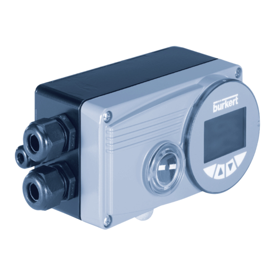
Type 8792, 8793
Positioner
Electropneumatic position controller
Elektropneumatischer Stellungsregler
Quickstart
English
Deutsch
2.
symbols
The following symbols are used in these instructions.
Danger!
Warns of an immediate danger!
•
Failure to observe the warning may result in a fatal or
serious injury.
Warning!
Warns of a potentially dangerous situation!
•
Failure to observe the warning may result in a serious or
fatal injury.
Caution!
Warns of a possible danger!
•
Failure to observe this warning may result in a medium
or minor injury.
note!
Warns of damage to property!
Important tips and recommendations for safe and
the flawless functioning of the device.
→
designates a procedure which you must carry out.
english
3
Inhaltsverzeichnis

Verwandte Anleitungen für bürkert 8792


Inhaltszusammenfassung für bürkert 8792
-
Seite 20: Der Quickstart
Der Quickstart muss gelesen und verstanden werden. • Bei Nichtbeachtung können schwere Verletzungen oder Tod die Folge sein. Der Quickstart für den Positioner Typ 8792-8793 erläutert Vorsicht! beispielhaft die Montage und Inbetriebnahme des Gerätes. Die ausführliche Beschreibung des Gerätes finden Warnt vor einer möglichen Gefährdung! -
Seite 21: Bestimmungsgemässe Verwendung
BesTimmungsgemässe 3.1. Vorhersehbarer Fehlgebrauch VerwenDung • Die Positioner Typ 8792 und Typ 8793 dürfen Sie nicht in explosionsgefährdeten Bereichen einsetzen. Bei nicht bestimmungsgemäßem Einsatz des Posi- • Speisen Sie in die Medienanschlüsse des Systems keine tioners Typ 8792 / 8793 können Gefahren für Per- aggressiven oder brennbaren Medien ein. - Seite 22 Typ 8692 6.1. allgemeine Beschreibung Die Stellung des Antriebs (Hub) wird entsprechend des Der Positioner Typ 8792 / 8793 ist ein digitaler, elektropneu- Stellungs-Sollwertes geregelt. Der Stellungs-Sollwert kann matischer Stellungsregler für pneumatisch betätigte Stetig- durch ein externes Einheitssignal vorgegeben werden.
-
Seite 23: Aufbau Des Positioners
Typ 8792, 8793 Technische DaTen 6.3. aufbau des Positioners 7.3.1. Betriebsbedingungen Mechanische Stellungsanzeige hinWeis! Bedienmodul mit Beim Einsatz im Außenbereich kann das Gerät durch Display und Tasten Sonneneinstrahlung und Temperaturschwankungen belastet werden, die Fehlfunktionen oder Undichtheiten Arbeitsanschluss 2 bewirken können! (Anschluss: A2) Überdruck-... -
Seite 24: Pneumatische Daten
Typ 8792, 8793 Induktive Näherungsschalter 7.3.4. Pneumatische Daten Steuermedium Qualitätsklassen nach DIN ISO 8573-1 Strombegrenzung 100 mA Staubgehalt Klasse 5, max. Teilchengröße 40 µm, Binäre Ausgänge galvanisch getrennt max. Teilchendichte 10 mg/m³ Strombegrenzung 100 mA, Ausgang wird bei Wassergehalt Klasse 3, max. Drucktaupunkt - 20 °C Überlast getaktet... -
Seite 25: Belegung Der Tasten
Typ 8792, 8793 8.3. Belegung der Tasten Belegung Betriebszustand / Taste Bedienebene (erscheint im unteren Balken) Belegung Betriebszustand / linke Wechsel in die Parametrier- AUTOMATIK oder Taste (erscheint im unteren Balken) Bedienebene Auswahl- ebene (MENU) HAND / taste Prozess bedienen... - Seite 26 ID.-Nr. 787 215 von Bürkert bezogen werden. Die zugehö- MENU POS INPUT* rigen Teile sind in der Tabelle „Anbausatz an Schubantriebe“ Anzeige der Ist-Position in der Bedienungsanleitung für den Postioner 8792 / 8793, des Ventilantriebes aufgelistet. (0 ... 100%) MENU INPUT CMD MANU...
-
Seite 27: Anbauwinkel Befestigen
Bügelmontage → Kurzen oder langen Hebel entsprechend dem Hub des Antriebes auswählen. (siehe Tabelle „Anbausatz an Schubantriebe“ in der Bedienungsanleitung für den Positioner 8792 / 8793). → Hebel wie im nachfolgenden Bild dargestellt zusam- menbauen (falls nicht vormontiert). deutsch deutsch 10.1.2. -
Seite 28: Hebelmechanismus Ausrichten
Typ 8792, 8793 Befestigung des Positioners mit Anbauwinkel bei Befestigung des Positioners mit Anbauwinkel bei Antrieben mit Gussrahmen: Antrieben mit Säulenjoch: → Anbauwinkel mit einer oder mehreren Sechskant- → ⑦, ⑪, Anbauwinkel mit den U-Bolzen Scheiben ⑧, ⑪ ⑩ schrauben... -
Seite 29: Remote-Betrieb Mit Externem Wegmesssystem
Typ 8792, 8793 → Positioner auf Anbaukonsole aufsetzen und mit 4 Schwenkantrieb befestigen ③ ④ Zylinderschrauben und Federringen befestigen (siehe nachfolgendes Bild). Anbau- konsole befestigen ④ ③ Wird nach dem Start der Funktion X.TUNE im Grafikdisplay die Meldung X.TUNE ERROR 5 →... - Seite 30 • Die Inbetriebnahme darf nur autorisiertes Fachpersonal Die Vorgehensweise ist in der Bedienungsanleitung mit geeignetem Werkzeug durchführen! für Typ 8792/8793 im Kapitel „Inbetriebnahme und Bedienung des Stellungsreglers / Zusatzfunktionen / Verletzungsgefahr durch ungewolltes Einschalten POS.SENSOR“ beschrieben. der Anlage und unkontrollierten Wiederanlauf! →...
-
Seite 31: Bezeichnung Der Rundsteckverbinder Und Kontakte
Typ 8792, 8793 elekTrische insTallaTiOn 11.2. Bezeichnung der rundsteckverbinder und 11.1. sicherheitshinweise kontakte WarnunG! Betriebsspannung Prozess-Istwert Binäre Ausgänge und diverse Verletzungsgefahr bei unsachgemäßer Installation! Signale • Die Installation darf nur autorisiertes Fachpersonal mit Stecker M12, Stecker M8, Buchse M8, geeignetem Werkzeug durchführen! -
Seite 32: Betriebsspannungrundstecker M12, 8-Polig
Anpassung des Positi- Prozessreglers 8793 oners auslösen (siehe Kapitel „13.2.1. Festlegen der → Den Prozessregler zunächst wie in Kapitel „ 11.3. Grundeinstellungen“). Anschluss des Stellungsreglers Typ 8792“ beschrieben anschließen. 11.4.1. steckerbelegungen des Prozess-istwert-eingangs (rundstecker m8) Eingangs-... - Seite 33 Typ 8792, 8793 Eingangs- DIP- Eingangs- DIP- Pin Belegung Äußere Beschaltung Pin Belegung Äußere Beschaltung typ* Schalter typ* Schalter 4 ... 20 mA nicht belegt Pt 100 nicht belegt - extern (siehe Prozess-Ist 4 ... 20 mA Prozess-Ist versorgt Hinweis...
-
Seite 34: Betriebsspannung
Typ 8792, 8793 12.2. klemmenbelegung bei 12.2.2. ausgangssignale zur leitstelle (z.B. sPs) - kabelverschraubung - (nur bei Option analoger stellungsregler Typ 8792 ausgang und/oder 12.2.1. eingangssignale der leitstelle Binärausgang erforderlich) (z. B. sPs) → Klemmen entsprechend der Ausführung (Optionen) des Positioners anschließen. -
Seite 35: Klemmenbelegung Bei Kabelverschraubung - Prozessregler Typ 8793
→ Den Prozessregler zunächst wie in Kapitel „ 12.2. Klem- versorgt Sensor menbelegung bei Kabelverschraubung - Stellungs- Takt-Eingang + Takt + regler Typ 8792“ beschrieben anschließen. nicht belegt 12.3.1. klemmenbelegungen des Takt-Eingang – Prozess-istwert-eingangs Takt – (GND) Eingangs- Klemme Belegung Äußere Beschaltung... -
Seite 36: Festlegen Der Grundeinstellungen
Typ 8792, 8793 13.2. inbetriebnahme Typ 8792 Automatische Anpassung des Stellungsreglers an die Betriebsbedingungen (X.TUNE) 13.2.1. Festlegen der grundeinstellungen WarnunG! Nehmen Sie bei der Inbetriebnahme des Positioners im Verletzungsgefahr durch plötzliche Ventilbewegung. Hauptmenü (MAIN) folgende Grundeinstellungen vor: Während der Ausführung der X.TUNE - Funktion bewegt Eingabe des Eingangssignals (INPUT) sich das Ventil selbsttätig aus seiner augenblicklichen... -
Seite 37: Manuelles Verändern Des Prozess-Sollwertes
Typ 8792, 8793 13.3.1. grundeinstellungen des Unempfindlichkeitsbereich des PID-Prozessreglers Prozessreglers Verstärkungsfaktor des Prozessreglers ENTER ENTER P.CONTROL PARAMETER DBND 0,1 % Nachstellzeit 0.00 Vorhaltezeit Arbeitspunkt 0,0% EXIT FILTER Filterung des Prozess-Istwert-Eingangs ENTER EXIT SETUP PV INPUT PV SCALE Angabe der Signalart für Prozess-Istwert... -
Seite 38: Entsorgung
Typ 8792, 8793 enTsOrgung → Entsorgen Sie das Gerät und die Verpackung umweltgerecht. hinWeis! Umweltschäden durch von Medien kontaminierte Geräteteile. • Geltende Entsorgungsvorschriften und Umweltbestim- mungen einhalten. Hinweis: Beachten Sie die nationalen Abfallbeseitigungsvorschriften. deutsch...