Inhaltsverzeichnis
Werbung
Verfügbare Sprachen
Verfügbare Sprachen
Quicklinks
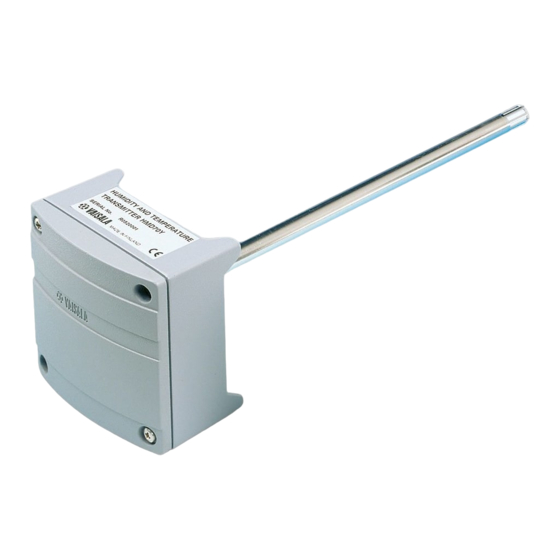
HUMIDITY TRANSMITTER HMD60U
HUMIDITY AND TEMPERATURE TRANSMITTER HMD60Y
MOUNTING
62 (2.44)
250 (9.84)
Ø 12
(0.47)
100 (3.94)
Mounting hole 82 (3.23)>>>
Figure 1 Dimensions of the HMD60U/Y
GROUNDING
Figure 2 Signal cable grounding with
bushing 18941HM
HMD60U/Y Operating Manual
The
temperature transmitters are two-wire
transmitters. They are duct mounted, and
the electronics can be disconnected
without dismantling the installation.
Mount the transmitter with two screws.
Place the drilling template on the duct
surface and drill the holes as indicated.
Remember to drill an additional hole for
calibration purposes. The calibration can
be conveniently performed on site with
the HMI41 or HM70 portable indicators
equipped with an appropriate probe and
optional calibration cable.
Open the lid and mount the cable
bushing set 18941HM. Ground the cable
by connecting the contact tongues inside
the bushing to an exposed length of cable
braid as shown in Figure 2.
short-circuit risk, do not expose more
cable
connecting the braid to the contact
tongues.
HMD60U/Y
humidity
braid
than
is
necessary
*M210276EN*
M210276EN-C
and
To minimize
for
1
Werbung
Inhaltsverzeichnis

Verwandte Anleitungen für Vaisala HMD60U


Inhaltszusammenfassung für Vaisala HMD60U
- Seite 1 HMI41 or HM70 portable indicators equipped with an appropriate probe and optional calibration cable. Mounting hole 82 (3.23)>>> Figure 1 Dimensions of the HMD60U/Y GROUNDING Open the lid and mount the cable bushing set 18941HM. Ground the cable by connecting the contact tongues inside the bushing to an exposed length of cable braid as shown in Figure 2.
-
Seite 2: Electrical Connections
HMD60U/Y Operating Manual M210276EN-C ELECTRICAL CONNECTIONS TEST Figure 3a. Electrical connections. RH GAIN TEST 3 4 5 RH OFFSET T OFFSET T GAIN Signal cables are connected to a removeable 5-pole screw connector. Make the connections according to Figure 3a above. RH test and T test connectors are used with the HMI41 or HM70 indicator equipped with an appropriate probe and optional calibration cable. - Seite 3 HMI41 or HM70 indicator equipped with attempt to clean the filter. appropriate probe optional calibration cable. adjustment needed, use the one-point calibration potentiometer. If you prefer to calibrate the HMD60U/Y transmitters against saturated salt solutions, use LiCl (11 %RH) and NaCl (75 %RH) solutions.
-
Seite 4: Technical Data
10...35 VDC (R L = 0Ω) GUARANTEE 20...35 VDC (R L =500Ω) Output signal 4...20 mA Vaisala issues a guarantee for the material and Operating temperature range: workmanship of this product under normal operating -5...+55 °C electronics conditions for one year from the date of delivery. -
Seite 5: Montage
HMD60U/Y Bedienungsanleitung M210276EN-C FEUCHTEMESSWERTGEBER HMD60U FEUCHTE- UND TEMPERATURMESSWERTGEBER HMD60Y Die Feuchte- und Temperaturmeßwert- MONTAGE geber HMD60U/Y sind Transmitter zur Verschaltung in Zweileitertechnik. Sie 62 (2.44) 250 (9.84) sind vorgesehen für die Installation in Kanälen und zeichnen sich aufgrund ihres modularen Aufbaus (Elektronik läßt sich separat ohne Demontage der gesamten Ø... -
Seite 6: Elektrische Anschlüsse
HMD60U/Y Bedienungsanleitung M210276EN-C ELEKTRISCHE ANSCHLÜSSE TEST RH GAIN TEST 3 4 5 RH OFFSET T OFFSET T GAIN Abbildung 3: Elektrische Anschlüsse Das Signalkabel wird an eine steckbare, 5-poligen Schraubklemme angeschlossen (Abb. 3). Die Buchsen RHtest und Ttest werden nur bei der Kalibrierung mit dem Feuchtehandmeßgerät/Kalibrator HMI41 zum Anschluß... - Seite 7 HMD60U/Y Bedienungsanleitung M210276EN-C AUFBAUKONZEPT DECKEL AUSBAU DER SONDE UND ELEKTRONIK: 1. Öffnen Sie den Gehäusedeckel. 2. Ziehen Sie die Schraubklemme von ihrem Sockel. 3. Lösen Sie die 2 Befestigungsschrauben. SCHRAUBKLEMME SCHRAUBEN 4. Ziehen Sie die Sonde vorsichtig aus dem Gehäuse.
-
Seite 8: Technische Daten
Krit. A (*zusätzlicher Test) < 0.1 °C Linearität GARANTIE Temperatursensor Pt1000 IEC 751 Kl. B Vaisala gewährt eine Garantie auf Material und Allgemeines Verarbeitung dieses Produktes bei Betrieb unter üblichen Bedingungen von einem (1) Jahr ab dem Datum Lieferscheines. Außergewöhnliche Versorgungsspannung 10...35 VDC (R L = 0Ω) - Seite 9 être effectuée aisément sur le site grâce à l'indicateur portable HMI41 équipé de la sonde appropriée et le câble de calibration (en option). Mounting hole 82 (3.23)>>> Schéma 1 Dimensions de la HMD60U/Y BLINDAGE Ouvrez couvercle installez l'ensemble de presse-étoupe 18941HM.
-
Seite 10: Connexions Electriques
HMD60U/Y Mode d'emploi M210276EN-C CONNEXIONS ELECTRIQUES TEST RH GAIN TEST 3 4 5 RH OFFSET T OFFSET T GAIN Schéma 3: Connexions électriques Les câbles de signaux sont connectés à un bornier à vis 5 pôles. Branchez suivant le schéma 3 ci-dessus. Les connecteurs RH et T test sont utilisés avec l'indicateur HMI41 équipé... - Seite 11 N'essayez pas de nettoyer le filtre. et le câble de calibration. Si un ajustage est nécessaire, utilisez le potentiomètre offset de l'humidité. Si vous préférez calibrer les transmetteurs HMD60U/Y acev des solutions salines saturées, utilisez les solutions LiCl (11 %HR) et NaCl (75 %HR).
-
Seite 12: Fiche Technique
Ce matériel est conforme à la directive CE. GARANTIE meilleur que 0.1 °C Linéarité Vaisala garantit le matériel et la main d'oeuvre de ce Capteur Pt1000 IEC 751 classe B produit dans les conditions normales d'utilisation pour un (1) an à partir de la date de livraison. Les dommages dus à... - Seite 13 отверстие для калибровки. Калибровку можно выполнить на месте установки с помощью портативных индикаторов HMI41 или HM70, оснащенных подхо- дящим датчиком и дополнительным калибровочным кабелем. Монтажное отверстие 82 (3,23) Рисунок 1. Размеры измерителя HMD60U/Y ЗАЗЕМЛЕНИЕ Необходимо открыть крышку и установить комплект...
-
Seite 14: Электрические Соединения
HMD60U/Y. Руководство по эксплуатации M210276EN-C ЭЛЕКТРИЧЕСКИЕ СОЕДИНЕНИЯ ПРОВЕРКА Рисунок 3а. Электрические соединения УСИЛЕНИЕ ПРОВЕРКА 3 4 5 СМЕЩЕНИЕ RH УСИЛЕНИЕ T СМЕЩЕНИЕ T +T -T или или мА мА мА мА Сигнальные кабели подключаются к съемному 5-контактному винтовому зажиму. Выполните подключения, как показано выше на рис. 3а. Испытательные разъемы... - Seite 15 HMD60U/Y. Руководство по эксплуатации M210276EN-C БЛОК ЭЛЕКТРОНИКИ СНЯТИЕ ГОЛОВКИ ДАТЧИКА 1. Откройте крышку. Крышка 2. Отсоедините винтовой зажим. 3. Открутите винты (2 шт.). 4. Аккуратно вытащите головку датчика. УСТАНОВКА ГОЛОВКИ ДАТЧИКА Винтовой зажим Винты 1. Вставьте головку датчика на место.
-
Seite 16: Технические Данные
Выходной сигнал 4—20 мА Диапазон рабочих ГАРАНТИЯ температур: блок электроники От -5 до +55 °C Компания Vaisala предоставляет гарантию на материалы головка датчика От -40 до +80 °C и качество изготовления данного прибора в течение Диапазон одного года с момента поставки... - Seite 17 HMD60U/Y 取扱説明書 M210276EN-C 蓋を開け、ケーブルブッシングセット 18941HM を取り付けます。図 2 に示すとおり、ブッシング内の接点突起 をケーブル編組の露出部分に接続して接 地します。 短絡が発生するリスクを最小限に抑える ために、編組を接点突起に接続するため に必要となる長さ以上にケーブル編組を 露出させないでください。...
- Seite 18 HMD60U/Y 取扱説明書 M210276EN-C...
- Seite 19 HMD60U/Y 取扱説明書 M210276EN-C...
- Seite 20 HMD60U/Y 取扱説明書 M210276EN-C INTERCAP 15778HM ...