
Verwandte Anleitungen für Vaisala GMW20


Inhaltszusammenfassung für Vaisala GMW20
- Seite 1 User’s Guide www.vaisala.com Vaisala CARBOCAP® Carbon Dioxide Transmitter Series GMW20 M210196EN-B...
- Seite 2 User’s Guide _____________________________________________________ GMW20...
-
Seite 3: Inhaltsverzeichnis
User’s Guide _____________________________________________________ GMW20 Table of Contents Basics of the GMW20 Series ..........2 Mounting ..................2 Electrical Connections ............4 Power Supply Requirements..........5 Technical Data ................7 Relays and Other Accessories ..........8 Dimensions (in Millimeters)........... 9... -
Seite 4: Basics Of The Gmw20 Series
In case adjustment is needed, contact Vaisala Service or local Vaisala representative. The reading of the GMW20 can be checked and adjusted with the serial com adapter 19040GM and the calibration software available from www.vaisala.com. The checking in the field can also be done with calibration gas and a multimeter. - Seite 5 User’s Guide _____________________________________________________ GMW20 Figure 1 Cable routing Thread the power wires and output signal wire through the center hole of the back plate. In case of surface wiring, make (e.g.with a pliers) cut-out by removing the attenuated part at lower edge of the back plate.
-
Seite 6: Electrical Connections
User’s Guide _____________________________________________________ GMW20 Electrical Connections See the requirements for the power supply in the Technical Data section. Connect the nominal 24 V supply on the PCB between the terminals + and -. Connect the common wire to terminal 0 and the other wire either to terminal V (voltage output) or to the terminal mA (current output). -
Seite 7: Power Supply Requirements
User’s Guide _____________________________________________________ GMW20 Power Supply Requirements The GMW20 uses a nominal 24 VAC/VDC power supply maintaining a voltage of 18...30 VDC or 20...26 VAC for all load conditions and all mains voltages. Although the power input includes a halfwave rectifier, it is recommended to use a DC supply to avoid current peaks (Current consumption: peak 170 mA, average 85 mA). - Seite 8 User’s Guide _____________________________________________________ GMW20 CONTROLLER GMW20 Supply Signal 24VAC voltage output GMW20 Supply Signal 24VAC voltage output Figure 3 Connection of separate AC supplies (recommended) GMW20 CONTROLLER Signal 24VAC output SHAR ED Supply COMMON voltage LINE GMW20 Supply Signal voltage...
-
Seite 9: Technical Data
User’s Guide _____________________________________________________ GMW20 Technical Data Property Description / value Measuring ranges 0 ... 2000 ppm CO 0 ... 5000 ppm CO 0 ... 10 000 ppm CO 0 ... 20 000 ppm CO Accuracy at 25 °C against certified... -
Seite 10: Relays And Other Accessories
User’s Guide _____________________________________________________ GMW20 Weight GMW21 100g GMW21 with display 130g GMW22 GMW22 with display 120g Relays and Other Accessories Transmitters can be ordered with or without relays. The default relay trigger point has been set to 1000 ppm. This can be changed with the optional software kit 19222GM. -
Seite 11: Dimensions (In Millimeters)
User’s Guide _____________________________________________________ GMW20 Dimensions (in Millimeters) 66.7 Figure 5 GMW21 and GMW21D 66.7 Figure 6 GMW22 and GMD22D... -
Seite 12: Legal Notice
The contents are subject to change without prior notice. Please observe that this manual does not create any legally binding obligations for Vaisala towards the customer or end user. All legally binding commitments and agreements are included exclusively in the applicable supply contract or Conditions of Sale. -
Seite 13: Co2-Messwertgeber Vaisala Carbocap® Der Serie Gmw20
Benutzerhandbuch www.vaisala.com CO2-Messwertgeber Vaisala CARBOCAP® der Serie GMW20... - Seite 14 Benutzerhandbuch _______________________________________________ GMW20...
- Seite 15 Benutzerhandbuch _______________________________________________ GMW20 Inhalt Allgemeine Informationen zur Serie GMW20 ....2 Montage ................... 2 Elektrische Anschlüsse ............... 4 Anforderungen der Stromversorgung........5 Technische Daten ................. 7 Relais und weiteres Zubehör............ 8 Abmessungen (in Millimeter) ........... 9...
-
Seite 16: Allgemeine Informationen Zur Serie Gmw20
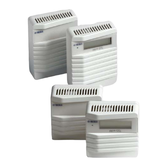
Benutzerhandbuch _______________________________________________ GMW20 Allgemeine Informationen zur Serie GMW20 In Vaialas Messwertgebern der Serie GMW20 wird ein auf Silikon basierender CARBOCAP -Sensor verwendet, der einwandfreie Stabilität und Zuverlässigkeit garantiert. Die Serie besteht aus den folgenden Messwertgebertypen: GMW21 und Displayversion GMW21D... - Seite 17 Benutzerhandbuch _______________________________________________ GMW20 Abbildung 1 Verkabelung Ziehen Sie das Stromkabel und das Ausgangssignalkabel durch die Öffnung am Rückwandblech. Wird keine UP- Dose verwendet, durchstoßen Sie (z. B. mit einer Zange) eine Öffnung für das Kabel, indem Sie die dünnere Stelle am unteren Rand der Bodenplatte entfernen.
-
Seite 18: Elektrische Anschlüsse
Benutzerhandbuch _______________________________________________ GMW20 Elektrische Anschlüsse Informationen zu den Anforderungen der Stromversorgung finden Sie im Abschnitt mit den technischen Daten. Die Versorgungsspannung von 24 V muss zwischen den Klemmen + und – auf der Hauptplatine angeschlossen werden. Die gemeinsame Masseader wird an Klemme 0 und die Signalader an Klemme V (Spannungsausgang) oder an Klemme mA (Stromausgang) angeschlossen. -
Seite 19: Anforderungen Der Stromversorgung
Benutzerhandbuch _______________________________________________ GMW20 Anforderungen der Stromversorgung Der Messwertgeber der Serie GMW20 wird mit einer Nennspannung von 24 V AC/V DC betrieben. Die Stromversorgung sollte eine Spannung zwischen 18 und 30 V DC oder 20 und 26 V AC bei allen Lastbedingungen und Netzspannungsschwankungen bereitstellen können. - Seite 20 Benutzerhandbuch _______________________________________________ GMW20 STEUERGERÄT GMW20 AUS- 24 V GANG Versorgung- Signalaus- 24 V AC sspannung gang GMW20 AUS- 24 V GANG Versorgung- Signalaus- 24 V AC gang sspannung Abbildung 3 Anschluss separater AC-Versorgungen (empfohlen) GMW20 STEUERGERÄT AUS- 24 V Signalaus-...
-
Seite 21: Technische Daten
Benutzerhandbuch _______________________________________________ GMW20 Technische Daten Eigenschaft B eschreibung/Wert Messbereiche 0 ... 2000 ppm CO 0 ... 5000 ppm CO 0 ... 10.000 ppm CO 0 ... 20.000 ppm CO Genauigkeit bei 25 °C gemäß (2 % v. Ew. + 2 % des... -
Seite 22: Benutzerhandbuch
Benutzerhandbuch _______________________________________________ GMW20 Gewicht GMW21 100 g GMW21 mit Display 130 g GMW22 90 g GMW22 mit Display 120 g Relais und weiteres Zubehör Messwertgeber können mit oder ohne Relais bestellt werden. Der Relaisschaltpunkt wurde werkseitig auf 1000 ppm eingestellt. Dieser kann mit dem optionalen Softwarezubehör 19222GM geändert werden. -
Seite 23: Abmessungen (In Millimeter)
Benutzerhandbuch _______________________________________________ GMW20 Abmessungen (in Millimeter) 66.7 Abbildung 5 GMW21 und GMW21D 66.7 Abbildung 6 GMW22 und GMW22D... -
Seite 24: Rechtlicher Hinweis
Inhalts dieses Handbuchs an Dritte. Der Inhalt kann ohne vorherige Ankündigung geändert werden. Diese Anleitung ist keine rechtsverbindliche Vereinbarung zwischen Vaisala und dem Kunden oder Benutzer. Alle rechtsverbindlichen Verpflichtungen und Vereinbarungen sind ausschließlich im anwendbaren Liefervertrag oder den Verkaufsbedingungen enthalten. - Seite 25 取扱説明書 www.vaisala.com ヴァイサラ CARBOCAP® 変換器シリーズ GMW20...
- Seite 26 取扱説明書 _______________________________________________________ GMW20...
- Seite 27 取扱説明書 _______________________________________________________ GMW20 目次 GMW20 シリーズの基本 ..........2 取り付け ..............2 電気的接続 ............... 4 電源要件..............5 技術データ ..............7 リレーおよびその他のアクセサリー........8 寸法 (mm)..............9...
-
Seite 28: Gmw20 シリーズの基本
セ ンサを使用し、優れた安定性と信頼性を備えています。このシリーズは以下の 種類の変換器で構成されています。 GMW21 およびディスプレイバージョン GMW21D (80x108.5x35) mm (80x80x35) mm GMW22 およびディスプレイバージョン GMW22D GMW20 シリーズ変換器は工場から出荷される際に校正されています。一般 的な環境では、5 年間隔で校正を行うことをお勧めします。調整が必要な場 合は、ヴァイサラ サービスまたはお近くのヴァイサラ代理店にお問い合わせく ださい。 GMW20 は連続アダプター19040GM および www.vaisala.com からの口径測 定ソフトウェアと調節することができる。現地での確認は、校正用ガスとマルチ メータを使用して行うこともできます。 取り付け GMW20 は、標準の壁面ボックスや壁面に取り付け可能な状態で出荷 されています。 変換器を取り付ける壁面にドリルで穴を開け、その穴から配線を引き出 します。 底部にある、カバーと背面プレートの間のスロットにドライバーのヘッド を差し込んで回し、変換器のカバーを開きます。 ドライバーで上に押し上げ、プリント回路基板 (PCB) を取り外します (3 ページの 図 1 を参照)。... - Seite 29 取扱説明書 _______________________________________________________ GMW20 図 1 ケーブル配線 電源配線と出力信号配線を背面プレートの中央の穴に通します。壁面 に配線する場合、(ペンチなどで) 背面プレート下部の端にある薄い部 分を取り外して切り欠きを入れます。 基盤の穴と開けた穴の中心を合わせ、基盤を壁面にネジで固定します。 PCB をラッチピン上に位置合わせして基盤に取り付け、所定の位置に はめ込まれるまで右上隅を押し込みます。GMW21D または GMW22D を使用している場合は、PCB 上部にディスプレイモジュールを取り付け ます。 続いて「電気的接続」の作業を行います。...
-
Seite 30: 電気的接続
取扱説明書 _______________________________________________________ GMW20 電気的接続 電源の要件については、「技術データ」を参照してください。 PCB の公称 24 V 電源を端子 + と端子 - の間に接続します。 共通配線を端子 0 に、他の配線を端子 V (電圧出力) または端子 mA (電流出力) に接続します。 ジャンパー 0/4 mA で次のいずれかの電流出力を選択します。 – 4~20 mA: ジャンパーでピンを短絡させる (初期設定) – 0~20 mA: ジャンパーを外す (破棄しないでください) ユニットにアクセサリー (リレー、ディスプレイとリレー、LonWorks イン... -
Seite 31: 電源要件
取扱説明書 _______________________________________________________ GMW20 電源要件 GMW20 では、公称 24 VAC/VDC 電源を使用し、あらゆる負荷条件および あらゆる主電源電圧に対して 18~30 VDC または 20~26 VAC を維持していま す。電源入力には半波整流器が含まれていますが、 DC 電源を使用してピーク電流 (電流消費 : ピーク時 170 mA、平均 85 mA) を回避することをお勧めします。 24 VAC 電源への接続 複数の変換器を 1 つの 24 VAC 変圧器に接続している場合、コモンループ が形成され、短絡が発生する危険が大きくなります。この状況を回避するため に、各変換器に個別のフローティング電源を使用することをお勧めします (図 3 を参照)。... - Seite 32 取扱説明書 _______________________________________________________ GMW20 コントローラ GMW20 24 V 信号出力 電源電圧 24 VAC GMW20 24 V 信号出力 電源電圧 24 VAC 図 3 個別の AC 電源の接続 (推奨) GMW20 コントローラ 24 V 信号出力 24 VAC 電源 電圧 GMW20 24 V 電源 信号出力 電圧 図 4...
-
Seite 33: 技術データ
取扱説明書 _______________________________________________________ GMW20 技術データ 特性 説明/値 測定範囲 0~2000 ppm CO 0~5000 ppm CO 0~10 000 ppm CO 0~20 000 ppm CO 25 °C での認定工場基準に対する精度 (範囲の 2 % + 指示値の 2 %) (再現性と校正の不確かさを含む) 長期安定性 < 範囲の 5 %/5 年間 応答時間 (0~63 %) 1 分... -
Seite 34: リレーおよびその他のアクセサリー
取扱説明書 _______________________________________________________ GMW20 リレーおよびその他のアクセサリー 変換器はリレー付きまたはリレーなしで注文できます。初期設定では、リレー のトリガーポイントは 1000 ppm に設定されています。トリガーポイントは、オプ ションのソフトウェアキット 19222GM で変更できます。 説明 注文コード ディスプレイおよびリレー出力オプション GMI21 リレー出力オプション GMR20 信号付き LonWorks モジュール GML20 (ディスプレイオプション追加時は利用できません) 信号および温度信号付き LonWorks モジュール (ディ GML20T スプレイオプション追加時は利用できません) GMW21 用アナログ温度モジュール GMA20T (ディスプレイオプション追加時は利用できません) シリアル COM アダプター 19040GM 現地検証用ハンディタイプメーター GM70... -
Seite 35: 寸法 (Mm)
取扱説明書 _______________________________________________________ GMW20 寸法 (mm) 66.7 図 5 GMW21 および GMW21D 66.7 図 6 GMW22 および GMW22D... - Seite 36 法律上の表示 © Vaisala 2010 本取扱説明書のいずれの部分も、電子的または機械的手法 (写真複写も含む) であ ろうと、またいかなる形式または手段によっても複製してはならず、版権所有者の書面 による許諾なしに、その内容を第三者に伝えてはなりません。 本取扱説明書の内容は予告なく変更されることがあります。 本取扱説明書は、顧客あるいはエンドユーザーに対してヴァイサラ社を法的に拘束す る義務を生じさせるものではないことをご承知ください。法的に拘束力のあるお約束あ るいは合意事項はすべて、該当する供給契約書または販売条件書に限定して記載さ れています。 保証 保証については、以下をご参照ください。www.vaisala.com/services/warranty.html 本製品は、2 年間の延長保証の対象です。 技術サポート 技術的なお問い合わせについては、以下まで E メールでヴァイサラ社技術サ ポートにご連絡ください。 helpdesk@vaisala.com ヴァイサラサービスセンターのお問い合わせ窓口については、以下をご参照 ください。 www.vaisala.com/services/servicecenters.html...
- Seite 37 操作手册 www.vaisala.com Vaisala CARBOCAP® 二氧化碳变送器系列 GMW20...
- Seite 38 操作手册_________________________________________________________ GMW20...
- Seite 39 操作手册_________________________________________________________ GMW20 目录 GMW20 系列的基本功能 ............2 安装....................2 电气连接..................4 电源要求..................5 技术数据..................7 继电器和其他附件................. 8 尺寸(以毫米表示)..............9...
-
Seite 40: 操作手册
____________________________________ GMW20 操作手册 GMW20 系列的基本功能 Vaisala 的 GMW20 系列变送器使用基于硅的 CARBOCAP 传感器, 铸就了变送器卓越的稳定性和可靠性。该系列包括以下变送器类型: GMW21 和显示屏版本 GMW21D (80x108.5x35) mm GMW22 和显示屏版本 GMW22D (80x80x35) mm GMW20 系列变送器在出厂前已经进行了校准。在良好的环境中,推荐 的校准时间间隔为 5 年。如果需要进行调整,请与 Vaisala 服务或当地 的 Vaisala 代表联系。 GMW20 可以检查和调整与连续适配器 19040GM 和从 www.vaisala.com 的定标软件。使用校准气体和万用表也可以进行现 场检查。... - Seite 41 操作手册_________________________________________________________ GMW20 图 1 电缆线路 将电源线和输出信号线穿过后面板中间的孔。如果要进行表面配 线,请取下(如使用钳子)后面板下边缘的较薄部分,创造一个 开口。 使底座上的孔在所钻孔的上方居中,并使用螺钉将底座固定到 表面。 在闩销上方将印刷电路板对准,将印刷电路板安装到底座中,然后 向下按右上角,直至其卡入到位。使用 GMW21D 或 GMW22D 时,请将显示屏模块安装在印刷电路板上方。 “电气连接” 继续了解 部分。...
-
Seite 42: 电气连接
____________________________________ GMW20 操作手册 电气连接 请参见“技术数据”部分中对电源的要求。 在印刷电路板上的端子 + 和 – 之间连接 24 V 的标称电源。将公共 线连接到端子 0,将另一条线连接到端子 V(电压输出)或端子 mA(电流输出)。 使用跳线 0/4 mA 选择电流输出 – 4 ... 20 mA:跳线使针脚短接(默认情况) – 0 ... 20 mA:断开(不丢弃)跳线。 如果装置具有选用附件(继电器、显示屏和继电器、LonWorks 接口或温度模块),请按照适用手册中所述的过程执行,然后重新 定位外盖。 重新定位外盖。 电源端子 输出信号 端子 电流输 出跳线... -
Seite 43: 电源要求
操作手册_________________________________________________________ GMW20 电源要求 GMW20 使用 24 VAC/VDC 的标称电源,对于所有负载情况和所有电 源电压保持电压为 18...30 VDC 或 20...26 VAC。尽管电源输入包括半 波整流器,但建议使用直流电源来避免出现电流峰值(电流消耗:峰值 为 170 mA,平均为 85 mA)。 连接到 24 VAC 电源 将多个变送器连接到一个 24 VAC 变压器时,会形成一个公共循环,将 增加发生短路的风险。要避免出现此情况,建议为每个变送器使用单独 的浮动电源(请参见 图 3)。 如果多个变送器必须共享一个变压器,则相位 ( ) 必须始终连接到每个 变送器中的 24V 接头,从而通过控制器上的共享公共线保持“极性”... - Seite 44 ____________________________________ GMW20 操作手册 控制器 GMW20 信号输出 供电电压 24VAC GMW20 信号输出 供电电压 24VAC 图 3 单独交流电源的连接(推荐) GMW20 控制器 信号输出 24VAC 供电 电压 GMW20 供电 信号输出 电压 图 4 一个交流电源连接到多个变送器...
-
Seite 45: 技术数据
操作手册_________________________________________________________ GMW20 技术数据 参数 说明/值 测量范围 0 ... 2000 ppm CO 0 ... 5000 ppm CO 0 ... 10 000 ppm CO 0 ... 20 000 ppm CO 温度为 25 °C 时相对于认证的工厂参考 (范围的 2 % + 读数的 2 %)... -
Seite 46: 继电器和其他附件
____________________________________ GMW20 操作手册 继电器和其他附件 可以订购包括或不包括继电器的变送器。默认的继电器触发点设置为 1000 ppm。可以使用可选软件套件 19222GM 更改该设置。 说明 订货代码 显示屏和继电器输出选件 GMI21 继电器输出选件 GMR20 采用 CO 信号的 LonWorks 模块 GML20 (添加显示屏选件后不可用) 采用 CO 信号和温度信号的 LonWorks 模块 GML20T (添加显示屏选件后不可用) GMW21 的模拟温度模块(添加显示屏选件后 GMA20T 不可用) 串行通信适配器 19040GM 用于现场验证的手持式测量仪 GM70... -
Seite 47: 尺寸(以毫米表示
操作手册_________________________________________________________ GMW20 尺寸(以毫米表示) 66.7 图 5 GMW21 和 GMW21D 66.7 图 6 GMW22 和 GMW22D... - Seite 48 法律声明 © Vaisala 2010 未经版权所有人事先书面许可,不得以任何形式或手段, 无论是电子的还是机械的 (其中包括影印),对本手册的任何部分进行复制,也不得将本手册的内容传达 给第三方。 本手册内容如有变更,恕不另行通知。 请注意, 本手册并不会导致 Vaisala 公司要对客户或最终用户付任何连带法律责 任。 所有的法律连带责任和协议只包含在适用供货合同或销售条款中。 担保 有关担保信息,请访问我公司网站: www.vaisala.com/services/warranty.html 本产品包括 2 年的延长保修期 技术支持 有关技术问题,请通过电子邮件与 Vaisala 技术支持部门联系: helpdesk@vaisala.com 有关 Vaisala 服务中心的联系信息,请参见 www.vaisala.com/services/servicecenters.html...
- Seite 50 The contents are subject to change without prior notice. Please observe that this manual does not create any legally binding obligations for Vaisala towards the customer or end user. All legally binding commitments and agreements are included exclusively in the applicable supply contract or Conditions of Sale.