Herunterladen Inhalt Inhalt Diese Seite drucken
Inhaltsverzeichnis

Werbung

Verfügbare Sprachen

Verfügbare Sprachen

SLIP PRINTER
SP298 SERIES
USER'S MANUAL
MODE D'EMPLOI
BEDIENUNGSANLEITUNG
MANUALE DI ISTRUZIONI

Werbung

Inhaltsverzeichnis
loading

Inhaltszusammenfassung für Star SP298 SERIES

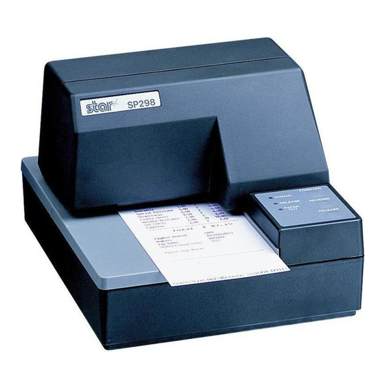
  • Seite 1 SLIP PRINTER SP298 SERIES USER’S MANUAL MODE D’EMPLOI BEDIENUNGSANLEITUNG MANUALE DI ISTRUZIONI...
  • Seite 2: Federal Communications Commission

    ESC/POS, TM-295, TM-290: Seiko Epson Corporation Notice • All rights reserved. Reproduction of any part of this manual in any form whatsoever, without STAR’s express per- mission, is strictly forbidden. • The contents of this manual are subject to change without notice.
  • Seite 3: Inhaltsverzeichnis

    Hexadecimal dump ..............17 Errors ..................18 Chapter 3: Command Summary .............. 20 Star Mode Commands .............. 20 ESC/POS Mode Commands (TM-295 emulation)....26 ESC/POS Mode Commands (TM-290 emulation)....28 Appendix A: Specifications ................. 120 Appendix B: Making DIP Switch Settings..........125 Appendix C: Memory Switch Settings ............
  • Seite 4: Chapter 1: Printer Setup

    Chapter 1: Printer Setup This chapter contains important information on setting up your printer. Be sure to read this chapter carefully before using the printer for the first time. In this chapter you will learn about: Choosing a place for the printer Unpacking and setting up the printer Installing the ribbon cassette Connecting to a host computer...
  • Seite 5: Unpacking The Printer

    Unpacking the printer Check to make sure that the carton contains each of the items shown in the following illustration. Ribbon cassette Printer User’s Manual Ferrite core Fastener If anything is missing, contact the dealer where you bought the printer and ask them to supply the missing part.
  • Seite 6: General Guide

    General guide The following illustrations describe the major components, buttons, and connectors of your printer. Printer cover Protects internal components. Control panel Three indicators show the printer status, and two switches provide control over printer functions. Power switch Document table Turns printer Supports the paper fed power on and off.
  • Seite 7: Removing The Printer Cover

    Removing the printer cover Push straight up on the ridged locations on the sides of the printer cover to remove it from the printer. To replace the cover, slide it back down into position. Gently press down on the cover until you hear it click securely into place. Installing the ribbon cassette Make sure that the printer’s paper release is activated (the paper is not held in place by the paper feed roller).
  • Seite 8 Remove the ribbon cassette from its packaging, and turn its knob in the direction indicated by the arrow to take up any slack in the ribbon. Holding the ribbon cassette so that the ribbon is facing down, install the cassette into the slip printer as shown in the illustration. Press gently but firmly on the cassette until it snaps securely into place.
  • Seite 9: Removing The Ribbon Cassette

    Removing the ribbon cassette Use the following procedure to remove the ribbon cassette from the slip printer when you want to replace it with a new one. Make sure that the printer is turned off and unplugged from its power outlet.
  • Seite 10 Plug the other end of the power cord to a standard household wall outlet. Use the power switch on the left side of the printer to turn power on and off. Important! We recommend that you unplug the printer from the power outlet whenever you do not plan to use it for long periods.
  • Seite 11: Connecting To Your Host Computer

    Connecting to your host computer The computer sends data to the printer through a cable to the printer’s interface (Serial Interface Connector Type: D-sub 25-pin or Parallel Interface Connector Type: 36-pin Centronics compatible). This printer does not come with a cable, so it is up to you to obtain one that suits your needs.
  • Seite 12 Pass the fastener through the ferrite core. 5 cm maximum Fastener Loop the fastener around the cable and lock it. Use scissors to cut off any excess. Pull and cut For a serial cable: Plug one end of the serial cable into the serial port of your computer, and the other end of the cable into the socket on the back of the printer.
  • Seite 13: Connecting To A Peripheral Unit

    Connecting to a peripheral unit You can connect a peripheral unit to the printer using a modular plug. The following describes how to install the ferrite core and make the actual connection. See “Modular plug” on page 137 for details about the type of modular plug that is required.
  • Seite 14: Inserting The Paper Into The Printer

    Loop the fastener around the cable and lock it. Use scissors to cut off any excess. Pull and cut Plug one end of the modular cable into the modular jack of the peripheral. Remove the modular jack cover from the back of the printer and plug the other end of the modular cable into the jack of the printer.
  • Seite 15: Autoside Loading

    Place a piece of the paper onto the printer’s document table and slide its right edge into the printer. Printing will be performed on the side of the paper that is facing up (the one you can see), starting from the top of the paper.
  • Seite 16 Push the right edge of the paper into the printer until it stops. At that time, the PAPER OUT indicator will go out, and the printer mechanism will automatically align the paper for printing from the top. Send data from your host computer to be printed on the paper. After printing, press the RELEASE button to automatically release the paper.
  • Seite 17: Chapter 2: Control Panel Operations

    Chapter 2: Control Panel Operations The control panel gives you some push-button control over the slip printer operation. It also includes indicator lights, which tell you the current status of the printer at a glance. FORWARD POWER RELEASE PAPER REVERSE RELEASE Indicator lights The following table describes the meaning of indicator lights when it is on, off,...
  • Seite 18: Buttons

    Buttons The following table describes the function of the three control buttons of the control panel. Button Description Feeds the slip paper forward, toward the back of the printer. One press FORWARD feeds one line, holding down performs continuous feed. Feeds the slip paper back, toward the front of the printer.
  • Seite 19 This is caused when mechanical parts of the printer get out of alignment. This happens only rarely and you may never experience it at all throughout the life of the printer. If you do have problems, use the following procedure to correct it. Turn on the printer and insert a piece of paper.
  • Seite 20: Hexadecimal Dump

    The dots alignment adjustment setting you selected is stored in printer memory and a pattern is printed using the selected setting followed by the message “Adjust Complete!” The printer ejects the paper after printing is complete. Note: You setting is not registered if you turn off printer power before pressing REVERSE to exit the Dot Alignment Adjust Mode.
  • Seite 21: Errors

    The method used by the printer to recover from a data receive error depends on the current command mode. Command mode Data Receive Error Recover Procedure Star mode The printer prints a question mark. Memory switch 4-0=0 : The printer prints a question mark. ESC/POS mode...
  • Seite 22 #9 and the trailing edge of the paper becomes 38.1 mm or less. In the Star Mode, this enters the print stop operation, but in the ESC/POS Mode, the print stop operation is not entered until the distance between print head pin #9 and the trailing edge of the paper becomes 27.3 mm or less.
  • Seite 23: Chapter 3: Command Summary

    Access the following URL for the latest version of this manual and for updates on supported commands: http://www.star-micronics.co.jp/service/ sp_sup_e.htm Star Mode Commands The following tables show the Star mode commands that are supported by this printer. Character Selection Hexadecimal Control Codes...
  • Seite 24 Hexadecimal Control Codes Function Codes <ESC> “W” n 1B 57 n Sets the magnification rate in character width <ESC> “h” n 1B 68 n Sets the magnification rate in character height <ESC> “–” “1” 1B 2D 31 Selects underlining <ESC> “–” <1> 1B 2D 01 <ESC>...
  • Seite 25 Print Position Control Hexadecimal Control Codes Function Codes <LF> Line feed <CR> Carriage Return <ESC> “a” n 1B 61 n Feeds paper n lines <HT> Horizontal tab <ESC> “A” n 1B 41 n Defines n/72-inch line spacing <ESC> “2” 1B 32 Sets n/72-inch line spacing <ESC>...
  • Seite 26 Dot Graphics Control Hexadecimal Control Codes Function Codes <ESC> “K” n <0> 1B 4B n 00 m 1 m 2 8 dot normal density graphics m 1 m 2 ... <ESC> “L” n 1 n 2 1B 4C n 1 n 2 m 1 m 2 8 dot high density graphics m 1 m 2 ...
  • Seite 27: Page Mode

    Slip Control Hexadecimal Control Codes Function Codes <ESC> <SI> n 1B 0F n Setting slip sensor <ESC> <FF> n 1B 0C n Slip function <ESC> <VT> m n 1B 0B m n Sets the paper eject direction/length <ESC><EM>mn<LF><NUL> 1B 19 n m 0A 00 Sets the wait time until the automatic clamp is activated Page mode Hexadecimal...
  • Seite 28 Hexadecimal Control Codes Function Codes <ESC><ACK><SOH> IB 06 01 Transmits automatic status <ESC><RS> “a” n IB IE 61 n Enables/disables automatic status <ESC> “?” <LF> <NUL> 1B 3F 0A 00 Resets printer hardware and produce a test print...
  • Seite 29: Esc/Pos Mode Commands (Tm-295 Emulation)

    ESC/POS Mode Commands (TM-295 emulation) The following table lists the TM-295 emulation commands that are supported by this printer. Hexadecimal Control Codes Function Codes <HT> Horizontal tab <LF> Line feed Paper eject in single sheet mode <FF> Paper mode print and return <DLE>...
  • Seite 30 Hexadecimal Control Codes Function Codes <ESC> L 1B 4C Selects page mode <ESC> R 1B 52 Selects international character set <ESC> T 1B 54 Selects direction for page mode character printing <ESC> U 1B 55 Selects print direction <ESC> V 1B 56 Designates/cancels 90˚...
  • Seite 31: Esc/Pos Mode Commands (Tm-290 Emulation)

    ESC/POS Mode Commands (TM-290 emulation) The following table lists the TM-290 emulation commands that are supported by this printer. Hexadecimal Control Codes Function Codes <HT> Horizontal tab <LF> Line feed <FF> Paper eject in single sheet mode <ESC> SP 1B 20 Sets size of space to right of character <ESC>...
  • Seite 32 Hexadecimal Control Codes Function Codes <ESC> R 1B 52 Selects international character set Selects the paper-end sensor for sending the no-paper <ESC> c3 1B 63 33 signal <ESC> c4 1B 63 34 Selects the paper-end sensor for stopping printing <ESC> c5 1B 63 35 Enables/disables control panel switches <ESC>...
  • Seite 33 Vidage hexadécimal..............47 Erreurs..................48 Chapitre 3: Résumé des commandes ............50 Les commandes du mode Star ..........50 Commandes du mode ESC/POS (Émulation de la TM-295)... 55 Commandes du mode ESC/POS (Émulation de la TM-290)... 57 APPENDICE: ....................120...
  • Seite 34: Chapitre 1: Configuration De L'imprimante

    Chapitre 1: Configuration de l’imprimante Ce chapitre vous fournira des informations importantes vous permettant de configurer votre imprimante. Veuillez lire attentivement ce chapitre avant d’utiliser l’imprimante pour la première fois. Vous y trouverez des informations qui vous aideront à : choisir l’emplacement de votre imprimante ;...
  • Seite 35: Déballage De L'imprimante

    Déballage de l’imprimante Contrôlez si la caisse contient bien tous les éléments illustrés ci-dessous. Cassette à ruban Imprimante Mode d’emploi Tore de ferrite Attache Si l’un des éléments mentionnés ci-dessus ne se trouve pas dans la caisse, adressez-vous au magasin où vous avez acheté l’imprimante et demandez que la pièce manquante vous soit fournie.
  • Seite 36: Description Générale

    Description générale Les illustrations ci-dessous vous indiquent les principaux éléments, touches et connecteurs de l’imprimante. Capot Protège les organes internes de l’imprimante. Tableau de commande Ce tableau comprend deux interrupteurs de commande des fonctions et trois témoins indiquant le statut de l’imprimante. Interrupteur d’alimentation Cet interrupteur vous permet...
  • Seite 37: Ouverture Du Capot

    Ouverture du capot Appuyez droit sur les sections cannelées des deux côtés du capot pour le détacher de l’imprimante. Pour remettre le capot en place, glissez-le en place et rabaissez-le. Appuyez délicatement sur le capot jusqu’à ce qu’il se verrouille dans un déclic. Installation de la cassette à...
  • Seite 38 Déballez la cassette à ruban et tournez son bouton dans la direction indiquée par la flèche afin de tendre correctement le ruban. Saisissez la cassette à ruban de sorte que le ruban soit orienté vers le bas et installez-la dans l’imprimante à papier fort de la manière illustrée. Appuyez sans forcer sur la cassette de sorte qu’elle soit correctement verrouillée.
  • Seite 39: Retrait De La Cassette À Ruban

    Retrait de la cassette à ruban Suivez les instructions ci-dessous lorsque vous souhaitez retirer la cassette à ruban afin de la remplacer. Assurez-vous que l’imprimante est hors tension et qu’elle est débranchée de la prise secteur. Retirez le capot de l’imprimante. Saisissez la cassette à...
  • Seite 40 Raccordez l’autre bout du cordon d’alimentation à une prise secteur de tension appropriée. Mettez l’imprimante sous et hors tension à l’aide de l’interrupteur d’alimentation situé sur le côté gauche de l’imprimante. Attention! Nous vous recommandons de débrancher l’imprimante du secteur lorsque vous ne comptez pas l’utiliser pendant une période prolongée.
  • Seite 41: Connexion À Votre Ordinateur-Hôte

    Connexion à votre ordinateur-hôte L’ordinateur communique les données à l’imprimante via le câble connecté à l’interface de l’imprimante (type de connecteur d’interface série : D-Sub à 25 broches ou type de connecteur d’interface parallèle : compatible Centronics à 36 broches). Ce câble n’est pas fourni avec l’imprimante. Vous devrez donc vous en procurer un.
  • Seite 42 Passez l’attache dans le tore de ferrite. 5 cm maximum Attache Passez l’attache autour du tore de ferrite et serrez-la. Coupez l’extrémité de l’attache à l’aide de ciseaux. Tirez et coupez Pour un câble série: Raccordez l’une des extrémités du câble en série au port d’interface en série de votre ordinateur, et l’autre extrémité...
  • Seite 43: Raccordement D'un Appareil Périphérique

    Raccordement d’un appareil périphérique Vous pouvez raccorder un appareil périphérique à l’imprimante à l’aide d’une fiche modulaire. Nous expliquons ci-dessous comment installer le tore de ferrite et faire le raccordement proprement dit. Pour les détails sur le type de fiche modulaire à...
  • Seite 44: Introduction Du Papier Dans L'imprimante

    Passez l’attache autour du tore de ferrite et serrez-la. Coupez l’extrémité de l’attache à l’aide de ciseaux. Tirez et coupez Raccordez une extrémité du câble modulaire à la prise modulaire du périphérique. Retirez le cache de prise modulaire au dos de l’imprimante, et raccordez l’autre extrémité...
  • Seite 45: Autoside Loading

    Placez une feuille de papier dans le bac à papier de l’imprimante et faites glisser son bord droit vers l’imprimante. L’impression se fera sur la face du papier tournée vers le haut (celle que l’on peut voir), à partir du haut du papier.
  • Seite 46 Poussez le bord droit du papier dans l’imprimante jusqu’à ce qu’il soit stoppé. A ce stade, le voyant d’absence de papier PAPER OUT s’éteint et le mécanisme de l’imprimante aligne automatiquement le papier pour commencer l’impression dans le haut de la feuille. Envoyez des données de votre ordinateur pour les imprimer sur le papier.
  • Seite 47: Chapitre 2: Tableau De Commande

    Chapitre 2: Tableau de commande Le panneau de commandes permet de contrôler le fonctionnement de l’imprimante de papier fort par boutons poussoir. Il contient également des témoins lumineux qui vous indiquent l’état de l’imprimante en un simple coup d’œil. FORWARD POWER RELEASE PAPER...
  • Seite 48: Touches

    Touches Le tableau ci-dessous vous explique la fonction des trois touches du tableau de commande. Touche Description Alimente le papier fort vers l’avant, vers le dos de l’imprimante. Une FORWARD pression fait avancer le papier d’une ligne, une pression continue produit une avance continue.
  • Seite 49 Ce problème est causé par un décalage des pièces mécaniques de l’imprimante. Ce problème est relativement rare et il est possible que vous ne le rencontriez jamais. Si toutefois vous rencontrez ce problème, suivez les instructions ci- dessous afin de le corriger. Mettez l’imprimante sous tension et introduisez un morceau de papier.
  • Seite 50: Vidage Hexadécimal

    Le réglage d’alignement des points que vous avez sélectionné est sauvegardé dans la mémoire, et l’imprimante imprime une série de lignes graduées correspondant à l’état d’impression sélectionné, suivie du message “Adjust Completed!”, vous indiquant que le réglage est terminé. L’imprimante éjecte ensuite le morceau de papier fort.
  • Seite 51: Erreurs

    Mode de commandes Procédure de correction d’une erreur de réception des données Mode Star L’imprimante imprime un point d’interrogation. Interrupteur mémoire 4–0=0 : l’imprimante imprime un point d’interrogation.
  • Seite 52 #9 de tête d’impression et le bord arrière du papier devient 38,1 mm ou moins. En Mode Star, ceci fait passer à l’arrêt d’impression, mais en mode ESC/POS, l’arrêt d’impression n’est pas atteint avant que la distance entre la broche #9 de tête d’impression et le bord arrière ne devienne 27,3 mm ou moins.
  • Seite 53: Chapitre 3: Résumé Des Commandes

    Pour obtenir la dernière version de ce manuel et pour les mises à jour des commandes supportées, consultez l’adresse URL suivante : http://www.star- micronics.co.jp/service/sp_sup_e.htm. Les commandes du mode Star Les tableaux ci-dessous vous montrent les commandes du mode Star qui sont supportées par l’imprimante. Sélection des caractères Code de contrôle Code hexadécimal...
  • Seite 54 Code de contrôle Code hexadécimal Fonction <ESC> “W” n 1B 57 n Règle l’indice d’amplification pour la largeur des caractères <ESC> “h” n Règle l’indice d’amplification pour la hauteur des 1B 68 n caractères <ESC> “–” “1” 1B 2D 31 Validation du soulignement <ESC>...
  • Seite 55 Commandes de position d’impression Code de contrôle Code hexadécimal Fonction <LF> Avance d’une ligne <CR> Retour chariot <ESC> “a” n 1B 61 n Avance du papier de n lignes <HT> Tabulation horizontale <ESC> “A” n 1B 41 n Sélection d’un interligne de n/72èmes de pouce <ESC>...
  • Seite 56 Commandes de graphiques en points Code de contrôle Code hexadécimal Fonction <ESC> “K” n <0> m1 m2 ... 1B 4B n 00 m1 m2... Impression de graphiques à densité normale <ESC> “L” n1 n2 m1 m2... 1B 4C n1 n2 m1 m2... Impression de graphiques à haute densité Impression de graphiques téléchargés Code de contrôle Code hexadécimal...
  • Seite 57: Autres Commandes

    Mode de page Code de contrôle Code hexadécimal Fonction <ESC> “n” 1B 6E Sélection du mode page <ESC> “!” 1B 21 Sélection du mode ligne <ESC> “*” ... 1B 2A ... Réglage de la zone d’impression en mode page <ESC> “T” n 1B 54 n Sélection du sens d’impression en mode page <FF>...
  • Seite 58: Commandes Du Mode Esc/Pos (Émulation De La Tm-295)

    Commandes du mode ESC/POS (Émulation de la TM-295) Le tableau ci-dessous donne la liste des commandes d'émulation de la TM-295 qui sont supportées par l'imprimante. Code de contrôle Code hexadécimal Fonction <HT> Tabulation horizontale <LF> Avance de ligne Ejection du papier en mode une feuille <FF>...
  • Seite 59 Code de contrôle Code hexadécimal Fonction <ESC> L 1B 4C Sélection du mode page <ESC> R 1B 52 Sélection du jeu de caractères internationaux Sélection du sens d’impression pour l’impression des <ESC> T 1B 54 caractères en mode page <ESC> U 1B 55 Sélection du sens d’impression <ESC>...
  • Seite 60: Commandes Du Mode Esc/Pos (Émulation De La Tm-290)

    Commandes du mode ESC/POS (Émulation de la TM-290) Le tableau ci-dessous donne la liste des commandes d'émulation de la TM-290 qui sont supportées par l'imprimante. Code de contrôle Code hexadécimal Fonction <HT> Tabulation horizontale <LF> Avance de ligne <FF> Ejection du papier en mode une feuille <ESC>...
  • Seite 61 Code de contrôle Code hexadécimal Fonction <ESC> R 1B 52 Sélection du jeu de caractères internationaux Commande au capteur de papier d’envoyer le signal <ESC> c3 1B 63 33 “papier épuisé”. Commande au capteur de papier d’interrompre <ESC> c4 1B 63 34 l’impression.
  • Seite 63 Sedezimaler Datenausdruck............77 Fehler ..................78 Kapitel 3: Zusammenfassung der Befehle ..........80 Befehle des Star-Modus.............. 80 Befehle des ESC/POS-Modus (TM295 Emulation) ....85 Befehle des ESC/POS-Modus (TM290 Emulation) ....87 ANHANG: ....................120 Der Anhang der Bedienungsanleitung ist nur im englischen Sprache.
  • Seite 64: Kapitel 1: Drucker-Einrichtung

    Kapitel 1: Drucker-Einrichtung Dieses Kapitel enthält wichtige Informationen zur Vorbereitung Ihres Druckers. Bitte dieses Kapitel sorgfältig durchlesen, bevor Sie den Drucker zum ersten Mal in Betrieb nehmen. In diesem Kapitel erfahren Sie Einzelheiten über: Wahl eines Aufstellungsorts für den Drucker Auspacken und Vorbereiten des Druckers Einsetzen der Farbbandkassette Anschließen an den Hostcomputer...
  • Seite 65: Auspacken Des Druckers

    Auspacken des Druckers Überprüfen Sie den Kartoninhalt, und vergewissern Sie sich, daß alle unten abgebildeten Teile vorhanden sind. Farbbandkassette Drucker Bedienungsanleitung Ferritkern Kabelbinder Falls Teile fehlen, wenden Sie sich zwecks Nachlieferung bitte an den Fachhandel, bei dem das Gerät gekauft wurde. Im Hinblick auf einen eventuellen zukünftigen Transport des Druckers empfiehlt es sich, den Lieferkarton und das gesamte Verpackungsmaterial aufzubewahren.
  • Seite 66: Allgemeine Anleitung

    Allgemeine Anleitung Die folgenden Abbildungen zeigen die Hauptbauteile des Druckers. Druckerabdeckung Schützt interne Bauteile. Bedienfeld Drei Anzeigen zeigen den Druckerzustand, und zwei Schalter erlauben Steuerung von Druckerfunktionen. Netzschalter Zum Ein- und Ausschalten Dokumentenauflage des Druckers. Stützt das Quittungspapier, das in den Quittungsdrucker eingeschoben wird.
  • Seite 67: Abnehmen Der Druckerabdeckung

    Abnehmen der Druckerabdeckung Die geriffelten Teile an den Druckerseiten gerade nach oben drücken, um die Abdeckung abzunehmen. Zum Schließen die Abdeckung wieder nach unten aufsetzen. Vorsichtig aufdrücken, bis sie hörbar einrastet. Einsetzen der Farbbandkassette Stellen Sie sicher, daß die Papierfreigabe des Druckers aktiviert ist (das Papier wird nicht von der Papier-Zufuhrrolle festgehalten).
  • Seite 68 Die Farbbandkassette aus der Verpackung nehmen, und den Knopf auf der Farbbandkassette im Uhrzeigersinn drehen, um eventuell vorhandene Bandschlaufen aufzuwickeln. Die Farbbandkassette so halten, daß das Farbband nach unten weist und die Kassette in den Drucker einsetzen, wie in der Abbildung gezeigt. Die Farbbandkassette sanft aber fest herunterdrücken, bis sie hörbar einrastet.
  • Seite 69: Entnehmen Der Farbbandkassette

    Entnehmen der Farbbandkassette Folgendermaßen verfahren, um die Farbbandkassette zum Austausch aus dem Drucker zu nehmen. Sicherstellen, daß der Drucker ausgeschaltet und von der Betriebsstromversorgung getrennt ist. Die Druckerabdeckung abnehmen. Die Farbbandkassette wie in der Abbildung gezeigt greifen und vorsichtig aus dem Druckmechanismus ziehen. Die unter “Einsetzen der Farbbandkassette”...
  • Seite 70 Den anderen Stecker des Netzkabels an eine Netzsteckdose anschließen. Den Netzschalter an der linken Seite des Druckers zum Ein- und Ausschalten verwenden. Wichtig! Wir empfehlen, den Netzstecker aus der Steckdose zu ziehen, wenn der Drucker längere Zeit lang nicht benutzt werden soll. Der Drucker sollte vorzugsweise an einem Platz aufgestellt werden, der leichten Zugang zur Netzsteckdose gewährt.
  • Seite 71: Anschließen An Den Hostcomputer

    Anschließen an den Hostcomputer Die Datenübertragung vom Computer zum Drucker erfolgt über ein Kabel, das an die Schnittstelle des Druckers (serieller Anschluß, Typ D-sub, 25 polig bzw. paralleler Anschluß, Typ Centronics-kompatibel, 36 polig) angeschlossen wird. Das Kabel ist im Lieferumfang dieses Druckers nicht enthalten und muß getrennt gekauft werden.
  • Seite 72 Führen Sie den Kabelbinder durch den Ferritkern. Maximum 5 cm Kabelbinder Führen Sie den Kabelbinder um das Kabel und sperren Sie ihn. Schneiden Sie überschüssiges Band mit einer Schere ab. Ziehen und abschneiden Für ein serielles Schnittstellenkabel: Ein Ende des Kabels an den seriellen Anschluß des Computers anschließen und das andere Ende an die Buchse an der Rückseite des Druckers an.
  • Seite 73: Anschluß An Ein Peripheriegerät

    Anschluß an ein Peripheriegerät Es kann ein Peripheriegerät an den Drucker mit einem Modularstecker angeschlossen werden. Im folgenden wird beschrieben, wie der Ferritkern angebracht und die Verbindung hergestellt wird. Siehe “Modularstecker” auf Seite 137 für den Typ von Modularstecker, der dazu erforderlich ist. Beachten Sie, daß...
  • Seite 74: Papier In Den Drucker Einlegen

    Das Befestigungsband um das Kabel wickeln und sperren. Schneiden Sie überschüssiges Band mit einer Schere ab. Ziehen und abschneiden Einen Stecker des Modularkabels in die Modularbuchse am Peripheriegerät stecken. Die Modularbuchsenabdeckung von der Rückseite des Druckers abnehmen, und den anderen Stecker des Modularkabels in die Modularbuchse am Drucker stecken.
  • Seite 75: Automatischer Papiereinzug (Autoside Loading ™ )

    Legen Sie ein Blatt Papier auf den Dokumententisch des Druckers und schieben Sie die rechte Ecke in den Drucker. Der Ausdruck erfolgt auf der Seite, die nach oben zeigt (die Seite, die Sie sehen können) und beginnt am oberen Rand des Blattes. Wichtig! Benutzen Sie kein verknicktes oder verwelltes Papier.
  • Seite 76 Schieben Sie die rechte Ecke des Blattes in den Drucker, bis Sie einen Widerstand spüren. Zu diesem Zeitpunkt wird die Anzeige PAPER OUT ausgehen und der Druckermechanismus zieht das Blatt automatisch ein und richtet es an der Druckstartposition aus. Senden Sie die Druckdaten, die auf dieses Blatt gedruckt werden sollen, von ihrem Computer zum Drucker.
  • Seite 77: Kapitel 2: Bedienfeld

    Kapitel 2: Bedienfeld Das Bedienungsfeld enthält einige Tasten, mit deren Hilfe Sie den Drucker bedienen künnen. Es enthält auch einige LED-Anzeigen, die Sie über den aktuellen Status des Druckers informieren. FORWARD POWER RELEASE PAPER REVERSE RELEASE Anzeigeleuchten Die folgende Tabelle stellt die Bedeutung des Leuchtens, Nichtleuchtens oder Blinkens der Anzeigeleuchten dar.
  • Seite 78: Tasten

    Tasten Die folgende Tabelle stellt die Funktion der drei Steuertasten am Bedienfeld dar. Taste Beschreibung Drücken, um das Quittungspapier zur Rückseite des Druckers FORWARD zuzuführen. Ein Tastendruck schiebt um eine Zeile vor, Gedrückthalten schiebt kontinuierlich vor. Drücken , um das Quittungspapier zur Vorderseite des Druckers REVERSE zurückzuführen.
  • Seite 79 Der Grund dafür ist, daß mechanische Teile des Druckers gegeneinander verschoben werden. Dies geschieht nur selten, und die meisten Anwender werden während der Lebensdauer des Druckers damit nicht konfrontiert werden. Falls aber dieses Problem auftritt, kann es auf folgende Weise behoben werden.
  • Seite 80: Sedezimaler Datenausdruck

    Die Einstellungen für die Punktausrichtung werden im Druckerspeicher gespeichert, und ein Muster wird mit der gewählten Einstellung ausgedruckt, gefolgt von der Meldung “Adjust Complete!”. Der Drucker gibt das Papier nach dem Druckvorgang aus. Hinweis: Wenn der Drucker ausgeschaltet wird, ohne die Taste REVERSE zum Verlassen des Punkteinstellmodus zu drücken, werden die Einstellungen nicht gespeichert.
  • Seite 81: Fehler

    Daten versucht zu beheben, ist davon abhängig, in welchen aktuellen Befehlsmodus der Drucker geschaltet ist. Befehlsmodus Methode zur Behebung des Datenempfangsfehlers Star-Modus Der Drucker druckt ein Fragezeichen. Speicherschalter 4-0 = 0:Der Drucker druckt ein Fragezeichen. ESC/POS-Modus Speicherschalter 4-0 = 1:Der Drucker löscht die empfangenen...
  • Seite 82 Der Hinterkantensensor (BOF) erkennt den Papier-Verbraucht-Zustand, wenn der Abstand zwischen dem Druckkopf-Pin Nr. 9 und der Hinterkante des Papiers 38,1 mm oder weniger wird. Im Star-Modus wird dadurch der Druck- Stopp-Modus eingeschaltet, aber im ESC/POS-Modus wird der Druck-Stopp- Modus nicht eingeschaltet, bevor der Abstand zwischen Druckkopf-Pin Nr. 9 und der Hinterkante des Papiers 27,3 mm oder weniger wird.
  • Seite 83: Kapitel 3: Zusammenfassung Der Befehle

    Kapitel 3: Zusammenfassung der Befehle Dieser Drucker unterstützt zwei verschiedene Befehlsmodi: den Star-Modus und den ESC/POS-Modus, Der Star-Modus emuliert den Befehlssatz der Star-Drucker. Der Modus ESC/ POS emuliert den Epson TM295 oder TM-290 Quittungsdrucker. In diesem Kapitel werden alle von diesem Drucker unterstützten Befehle aufgeführt.
  • Seite 84 Steuerbefehle Sedezimal-Codes Funktion <ESC> “W” n 1B 57 n Druck mit doppelter Zeichenbreite ein- bzw. ausschalten <ESC> “h” n 1B 68 n Druck mit doppelter Zeichenhöhe ein- bzw. ausschalten <ESC> “–” “1” 1B 2D 31 Unterstreichen einschalten <ESC> “–” <1> 1B 2D 01 <ESC>...
  • Seite 85: Ändern Der Druckposition

    Ändern der Druckposition Steuerbefehle Sedezimal-Codes Funktion <LF> Zeilenvorschub <CR> Wagenrücklauf <ESC> “a” n 1B 61 n Papiervorschub n Zeilen einstellen <HT> Nächste horizontale Tabulatorposition <ESC> “A” n 1B 41 n Zeilenabstand n/72 Zoll definieren <ESC> “2” 1B 32 Zeilenabstand von n/72 Zoll ausführen <ESC>...
  • Seite 86: Druck Von Rastergrafiken

    Druck von Rastergrafiken Steuerbefehle Sedezimal-Codes Funktion 1B 4B n 00 m1 m2 <ESC> “K” n <0> m1 m2 ... Grafikdruck in normaler Auflösung 1B 4C n1 n2 m1 m2 <ESC> “L” n1 n2 m1 m2 ... Grafikdruck in hoher Auflösung Druck von heruntergeladenen Zeichen Steuerbefehle Sedezimal-Codes...
  • Seite 87: Befehle Für Seitenmodus

    Befehle für Seitenmodus Steuerbefehle Sedezimal-Codes Funktion <ESC> “n” 1B 6E Seitenmodus wählen <ESC> “!” 1B 21 Zeilenmodus wählen <ESC> “*” ... 1B 2A ... Druckbereich im Seitenmodus einstellen <ESC> “T” n 1B 54 n Druckrichtung im Seitenmodus einstellen <FF> Im Seitenmodus drucken Weitere Befehle Steuerbefehle Sedezimal-Codes...
  • Seite 88: Befehle Des Esc/Pos-Modus (Tm295 Emulation)

    Befehle des ESC/POS-Modus (TM-295 Emulation) Die folgende Tabelle führt die TM-295 Emulationsbefehle aus, die von diesem Drucker unterstützt werden. Steuerbefehle Sedezimal-Codes Funktion <HT> Horizontaler Tab <LF> Zeilenvorschub Papierauswurf im Einzelblattmodus <FF> Papiermodus drucken und zurückschalten <DLE> <EOT> Übertragung in Echtzeit aktivieren (nur serielle 10 04 Schnittstelle) <CAN>...
  • Seite 89 Steuerbefehle Sedezimal-Codes Funktion <ESC> L 1B 4C Seitenmodus wählen <ESC> R 1B 52 Internationalen Zeichensatz wählen <ESC> T 1B 54 Richtung für Seitendruck-Zeichendruck wählen <ESC> U 1B 55 Wahl der Druckrichtung <ESC> V 1B 56 90˚ Zeichendrehung EIN/AUS <ESC> W 1B 57 Druckbereich für Seitenmodus-Druck einstellen <ESC>...
  • Seite 90: Befehle Des Esc/Pos-Modus (Tm290 Emulation)

    Befehle des ESC/POS-Modus (TM-290 Emulation) Die folgende Tabelle führt die TM-290 Emulationsbefehle aus, die von diesem Drucker unterstützt werden. Steuerbefehle Sedezimal-Codes Funktion <HT> Horizontaler Tab <LF> Zeilenvorschub <FF> Papierauswurf im Einzelblattmodus <ESC> SP 1B 20 Leerstelle rechts neben Zeichen einstellen <ESC>...
  • Seite 91 Steuerbefehle Sedezimal-Codes Funktion <ESC> R 1B 52 Internationalen Zeichensatz wählen <ESC> c3 1B 63 33 Papierende-Sensor für Papierende-Signal einstellenn <ESC> c4 1B 63 34 Papierende-Sensor für Druckabbruch einstellen <ESC> c5 1B 63 35 Bedienfeldschalter aktivieren/deaktivieren <ESC> d 1B 64 n Zeilen drucken oder vorschieben <ESC>...
  • Seite 93 Scaricamento esadecimale ............. 107 Errori..................108 Capitolo 3: Sommario dei comandi............110 Comandi del modo Star ............110 Comandi del modo ESC/POS (emulazione TM-295).... 115 Comandi del modo ESC/POS (emulazione TM-290).... 117 APPENDICE: ....................120 L’Appendice appare solo nella sezione in inglese di questo manuale.
  • Seite 94: Capitolo 1: Preparativi

    Capitolo 1: Preparativi Questo capitolo contiene informazioni importanti su come preparare la stampante. Assicurarsi di leggere attentamente questo capitolo prima di usare la stampante per la prima volta. In questo capitolo spieghiamo quanto segue: Scelta di un luogo per la stampante Disimballaggio e installazione della stampante Inserimento della cassetta del nastro Collegamento ad un computer ospite...
  • Seite 95: Disimballaggio Della Stampante

    Disimballaggio della stampante Controllare che lo scatolone contenga tutti gli elementi indicati nella seguente illustrazione. Cassetta del nastro Stampante Manuale di istruzioni Anello di ferrite Fascetta di fissaggio Se dovesse mancare qualcosa, contattare il concessionario da cui si è acquistata la stampante e richiedere la parte mancante.
  • Seite 96: Guida Generale

    Guida generale Le seguenti illustrazioni descrivono le parti principali, i tasti e i connettori della stampante. Coperchio della stampante Protegge i componenti interni. Pannello comandi Tre spie indicano lo stato della stampante e due interruttori permettono di controllare le funzioni della stampante.
  • Seite 97: Rimozione Del Coperchio Stampante

    Rimozione del coperchio stampante Spingere direttamente verso l’alto sulle zigrinature sui lati del coperchio stampante per rimuoverlo dalla stampante. Per rimettere il coperchio, abbassarlo in posizione. Premere leggermente sul coperchio fino a sentire che scatta in posizione. Inserimento della cassetta del nastro Assicurarsi che il meccanismo di rilascio carta della stampante sia attivato (la carta non viene mantenuta in posizione dal rullo di avanzamento carta).
  • Seite 98 Rimuovere la cassetta del nastro dalla confezione e girare la sua manopola nella direzione indicata dalla freccia per eliminare eventuali allentamenti del nastro. Tenendo la cassetta del nastro con il nastro rivolto verso il basso, inserire la cassetta nella stampante di moduli come indicato nell’illustrazione. Premere delicatamente ma con fermezza fino a che la cassetta scatta saldamente in posizione.
  • Seite 99: Rimozione Della Cassetta Del Nastro

    Rimozione della cassetta del nastro Usare il seguente procedimento per rimuovere la cassetta del nastro dalla stampante di moduli quando si desidera sostituirla con un’altra nuova. Assicurarsi che la stampante sia spenta e scollegata dalla presa di corrente. Rimuovere il coperchio della stampante. Afferrare la cassetta del nastro come illustrato e tirarla via dolcemente dal meccanismo di stampa.
  • Seite 100 Collegare l’altro capo del cavo di alimentazione ad una presa di corrente normale. Usare l’interruttore di alimentazione sul lato sinistro della stampante per accendere e spegnere. Importante! Consigliamo di scollegare la stampante dalla presa di corrente quando si prevede di non usarla per un lungo periodo. Per questo motivo, la stampante deve essere collocata in modo che la presa di corrente sia vicina e facilmente accessibile.
  • Seite 101: Collegamento Al Computer Ospite

    Collegamento al computer ospite Il computer invia dati alla stampante tramite un cavo collegato all’interfaccia della stampante (tipo connettore interfaccia seriale: D-sub a 25 terminali o tipo connettore interfaccia parallela: compatibile Centronics a 36 terminali). Questa stampante non è dotata di cavo, che deve essere acquistato a seconda delle esigenze di impiego.
  • Seite 102 Far passare la fascetta di fissaggio attraverso l’anello di ferrite. 5 cm massimo Fascetta di fissaggio Avvolgere la fascetta intorno al cavo e fissarla. Usare delle forbici per tagliare la parte in eccesso. Tirare e tagliare Per un cavo seriale: Collegare un capo del cavo seriale alla porta seriale del computer e l’altro capo alla presa sul retro della stampante.
  • Seite 103: Collegamento Ad Un'unità Periferica

    Collegamento ad un’unità periferica Si può collegare un’unità periferica alla stampante usando una spina modulare. Di seguito descriviamo come installare l’anello di ferrite ed eseguire il collegamento. Vedere “Modulare necessario” a pagina 137 per dettagli sul tipo di spina modulare necessario. Notare che la stampante non è dotata di spina o filo modulare, che devono essere acquistati in base alle esigenze di impiego.
  • Seite 104: Inserimento Della Carta Nella Stampante

    Avvolgere la fascetta intorno al cavo e fissarla. Usare delle forbici per tagliare la parte in eccesso. Tirare e tagliare Collegare un capo del cavo modulare alla presa modulare della periferica. Rimuovere il coperchio presa modulare dal retro della stampante e collegare l’altro capo del cavo modulare alla presa sulla stampante.
  • Seite 105: Autoside Loading

    Collocare un foglio di carta sul ripiano documenti della stampante ed inserire il bordo destro nella stampante. La stampa verrà eseguita sul lato della carta rivolto verso l’alto (quello visibile), partendo dal margine superiore del foglio. Importante! Non usare carta sgualcita o arricciata. In caso di utilizzo di carta a più copie, allineare esattamente i fogli.
  • Seite 106 Spingere il bordo destro della carta nella stampante fino al suo arresto. A questo punto, la spia PAPER OUT si spegnerà, e il meccanismo della stampante allineerà automaticamente la carta per la stampa partendo dal margine superiore. Inviare i dati da stampare sulla carta dal computer principale. Terminata la stampa, premere il tasto RELEASE per rilasciare automaticamente la carta.
  • Seite 107: Capitolo 2: Operazioni Con Il Pannello Comandi

    Chapter 2: Operazioni con il pannello comandi Il pannello di controllo consente di controllare il funzionamento della stampante tipo slip mediante l’uso di tasti. Esso comprende inoltre alcune spie luminose che consentono all’operatore di conoscere con una rapida occhiata lo stato operativo della stampante.
  • Seite 108: Tasti

    Tasti La seguente tabella descrive le funzioni dei tre tasti di controllo del pannello comandi. Tasto Descrizione Fa avanzare il modulo di carta in avanti, verso il retro della stampante. FORWARD Una pressione del tasto fa avanzare la carta di una riga, tenendo il tasto premuto viene eseguito l’avanzamento continuo.
  • Seite 109 Questo è causato da una perdita di allineamento delle parti meccaniche della stampante. Questo succede solo raramente e può non verificarsi mai durante l’uso della stampante. Se si hanno problemi, usare il seguente procedimento per correggerli. Accendere la stampante ed inserire un foglio di carta. Spegnere la stampante.
  • Seite 110: Scaricamento Esadecimale

    L’impostazione di allineamento punti selezionata viene conservata nella memoria della stampante e viene stampato uno schema che impiega l’impostazione selezionata seguito dal messaggio “Adjust complete!”. La stampante espelle la carta una volta completata la stampa. Nota: Le impostazioni non sono registrate se si spegne la stampante prima di premere REVERSE per uscire dal modo di regolazione allineamento punti.
  • Seite 111: Errori

    Il metodo usato dalla stampante per ripristinare un errore di ricezione dati dipende dal modo comandi attivo. Modo comandi Procedimento di soluzione errore di ricezione dati Modo Star La stampante stampa un punto di domanda. Interruttore di memoria 4-0=0: la stampante stampa un punto Modo ESC/POS interrogativo.
  • Seite 112 Quando il morsetto automatico è abilitato con l’interruttore di memoria 5-1, l’operazione di morsetto automatico viene eseguita circa 0,7 secondi (valore originale nel modo Star; il valore iniziale nel modo ESC/POS è di circa 1 secondo) dopo che la presenza della carta è stata individuata dai sensori TOF e BOF, dopo una condizione di carta esaurita.
  • Seite 113: Capitolo 3: Sommario Dei Comandi

    Chapter 3: Sommario dei comandi Questa stampante supporta due diversi modi di comando: il modo Star e il modo ESC/POS. Il modo Star emula i modelli precedenti di stampanti Star. Il modo ESC/POS emula la stampante slip Epson TM-295 o TM-290.
  • Seite 114 Codici di controllo Codici esadecimali Funzione Imposta il fattore d’ingrandimento per la larghezza del <ESC> “W” n 1B 57 n carattere <ESC> “h” n 1B 68 n Imposta il fattore d’ingrandimento per l’altezza del carattere <ESC> “–” “1” 1B 2D 31 Seleziona la sottolineatura <ESC>...
  • Seite 115 Controllo della posizione di stampa Codici di controllo Codici esadecimali Funzione <LF> Avanzamento riga <CR> Ritorno carrello <ESC> “a” n 1B 61 n Avanzamento carta di n righe <HT> Tabulazione orizzontale <ESC> “A” n 1B 41 n Definisce l’interlinea a n/72 di pollice <ESC>...
  • Seite 116 Controllo grafica a punti Codici di controllo Codici esadecimali Funzione 1B 4B n 00 m1 m2 <ESC> “K” n <0> m1 m2 ... Stampa la grafica a densità normale 1B 4C n1 n2 m1 m2 <ESC> “L” n1 n2 m1 m2 ... Stampa la grafica ad alta densità...
  • Seite 117: Altri Comandi

    Controllo moduli Codici di controllo Codici esadecimali Funzione <ESC> <SI> n 1B 0F n Impostazione sensore dello slip <ESC> <FF> n 1B 0C n Funzione di slip <ESC> <VT> m n 1B 0B m n Imposta la direzione/lunghezza dell’espulsione della carta Imposta il tempo di attesa per l’attivazione del blocco <ESC><EM>mn<LF><NUL>...
  • Seite 118: Comandi Del Modo Esc/Pos (Emulazione Tm-295)

    Codici di controllo Codici esadecimali Funzione <ESC> <RS> “a” n IB IE 61 n Abilita/disabilita lo stato automatico Ripristino hardware della stampante ed esecuzione di una <ESC> “?” <LF> <NUL> 1B 3F 0A 00 stampa di prova...
  • Seite 119 Comandi del modo ESC/POS (emulazione TM-295) La seguente tabella elenca i comandi di emulazione TM-295 supportati da questa stampante. Codici di controllo Codici esadecimali Funzione <HT> Tabulazione orizzontale <LF> Avanzamento di riga Espulsione carta in modo foglio singolo <FF> Stampa in modo pagina e ritorno <DLE>...
  • Seite 120: Comandi Del Modo Esc/Pos (Emulazione Tm-290)

    Codici di controllo Codici esadecimali Funzione <ESC> L 1B 4C Seleziona il modo pagina <ESC> R 1B 52 Selezione il gruppo caratteri internazionali Seleziona la direzione per la stampa caratteri del modo <ESC> T 1B 54 pagina <ESC> U 1B 55 Seleziona la direzione di stampa <ESC>...
  • Seite 121 Comandi del modo ESC/POS (emulazione TM-290) La seguente tabella elenca i comandi di emulazione TM-290 supportati da questa stampante. Codici di controllo Codici esadecimali Funzione <HT> Tabulazione orizzontale <LF> Avanzamento di riga <FF> Espulsione carta in modo foglio singolo <ESC> SP 1B 20 Imposta le dimensioni dello spazio a destra del carattere <ESC>...
  • Seite 122 Codici di controllo Codici esadecimali Funzione <ESC> R 1B 52 Selezione il gruppo caratteri internazionali Slezionare il sensore carta per l’invio del segnale di <ESC> c3 1B 63 33 assenza <ESC> c4 1B 63 34 Selezionare il sensore di fine carta per l’arresto <ESC>...
  • Seite 123: Appendix A: Specifications

    ESC/POS mode (TM-290 emulation) Interface Serial (RS-232C standard) Parallel (centronics compatible) Data Buffer Star mode: 2 K bytes / 35 bytes ESC/POS mode: 512 bytes / 35 bytes Reliability Mechanism (MCBF): 2.5 million lines Printer head life: 70 million characters...
  • Seite 124: Printing Specifications

    63mm Character Set Star Mode ASCII : 96 / Block Graphics : 64 / Special : 64 / Katakana : 64 / IBM Special : 64 / IBM Block Graphics : 50 / International :11 / Slashed Zero / Code Page 858 / Code Page 852...
  • Seite 125: Paper Specifications

    Paper Specifications Paper Width 80 to 182mm / 3.15″ to 7.17″ Paper Length 80 to 257mm / 3.15″ to 10.8″ Copies Original + 2 Paper Thickness 1-ply: 0.09 to 0.2mm / 0.0035″ to 0.0079″ Duplicates 0.12 mm (minimum for 2-ply forms) to 0.25 mm/0.0047″ to 0.0098″ <Maximum 0.2 mm when printing graphics>...
  • Seite 126 Paper Feed Drive Stepping motor Pitch Star Mode: Adjustable in 1/144″ units ESC/POS Mode: Adjustable in n/60″ units (approximate) Speed (while printing) 3.5″ per second Speed (while ejecting) 4.5″ per second Important! Slip paper must be flat, smooth, and free of curls, bends, wrinkles and folds, all...
  • Seite 127: Power Supply Specifications

    Power Supply Specifications Power Supply AC Adaptor PS48-24A, switching type Input 90 to 264V AC, 50/60Hz 24V DC ± 5%, 2.0A Output Plug 3-pin POWER JACK TCP 8927 (Hoshiden brand or equivalent.) Consumption Current Conditions: 24V, excluding external equipment driving Operating Continuous ASCII printing + paper feed: 0.6A (approximate averages)
  • Seite 128: Appendix B: Making Dip Switch Settings

    Appendix B: Making DIP Switch Settings The printer’s DIP switches let you specify communications parameters, receive buffer size, and emulation. This Appendix explains the settings you can make and tells you how to actually change DIP switch settings. Accessing the DIP switches The DIP switches are located inside the printer, underneath the document table.
  • Seite 129 It is not necessary to remove the document table completely, just move it enough so you can get at the DIP switches inside. (For Serial Interface) (For Parallel Interface) Note: If the document table seems to be getting caught on the rollers, it means that you are not pressing down at point (a) enough.
  • Seite 130 Switch 1 Switch 2 1200BPS 2400BPS 4800BPS 9600BPS Command Emulation Switch 7 Switch 8 Star mode ESC/POS (TM-295) ESC/POS (TM-290) Not used (*1) *1: Never set switch 7 to OFF at the same time that switch 8 is set to ON.
  • Seite 131 Reset input disabled Enable #31 pin (nInit) “Low” input Disable *3 Command Emulation Switch 7 Switch 8 Star mode ESC/POS (TM-295) ESC/POS (TM-290) Not used (*4) *1 Automatic status function When valid, the status occurrence conditions are as follows. Star mode: All status occurrences enabled.
  • Seite 132 *2 A reset can be performed with pin 31 on the interface by setting DIP switch 1 to ON (the factory default setting). In addition, when a reset can be performed with pin 31, setting DIP switch 2 to OFF sets up the unit to perform a reset when pin 31 and pin 36 are “LOW”.
  • Seite 133: Appendix C: Memory Switch Settings

    Appendix C: Memory Switch Settings Each memory switch is a 16-bit word store in EEPROM. For details on the functions and settings of memory switches, see the separate Programmer’s Manual. The table below shows the factory settings for the memory switches. Memory Switch Hexadecimal Code 0000...
  • Seite 134: Appendix D: Interface

    Direction Function Name — Frame ground Transmission data Receive data STAR Mode When Memory Switch 4-D = 0: Same as DTR signal When Memory Switch 4-D = 1: Always SPACE ESC/POS Mode Same as DTR signal N.C. Not connected • DIP Switch 9 = OFF STAR Mode Status of this signal is not checked.
  • Seite 135: Interface Connections

    Signal Direction Function Name INIT • DIP Switch 10 = OFF This signal not used. • DIP Switch 10 = ON This signal becomes reset signal. Printer is reset whenever signal is in space state with pulse width of 1mS or more. Interface Connections Refer to the interface specifications of the host for details on connecting to its interface connector.
  • Seite 136 D-2. Parallel Interface The two-way parallel interface is compatible with the IEEE1284 compatibility mode, nibble mode and byte mode. Refer to the separate programmer’s manual for details. Table of connection signals for each mode Compatibility Mode Nibble Mode Byte Mode Pin No.
  • Seite 137 Compatibility Mode Nibble Mode Byte Mode Pin No. Direction Signal Name Signal Name Signal Name nInit nInit nInit nFault nDataAvail/Data0,4 nDataAvail EXT GND — — Compulsion Status — — — — nSelectIn 1284Active 1284Active Note: 1. The prefix “n” on the signal name refers to low active signals. If the host does not have any one of the signal lines listed above, two-way communication fails.
  • Seite 138 3. Error condition This signal indicates the status of the paper sensor. [In Star mode] This signal goes to HIGH when either the TOF or the BOF sensor detects that there is no paper. The signal will go to LOW when both the PError TOF and BOF sensor detect that there is paper installed.
  • Seite 139 Signal Name IN/OUT Function Compulsion Compulsion signal (See page 138.) Status 2.2 kΩ pull-up Unused (However, this becomes a reset signal when DIP switch 1 is set nSelectIn to ON and DIP switch 2 is set to OFF. See page 128 for details.) This connector mates with an Amphenol 57-30360 connector Parallel interface connector (printer side)
  • Seite 140: Appendix E: Peripheral Unit Driver Circuit

    Appendix E: Peripheral Unit Driver Circuit This printer is equipped with a circuit for driving peripheral units, such as cash drawers. A 6-pin modular connector for connection of the peripheral unit is located on the back of the printer. To connect to the drive circuit, connect the peripheral unit to the modular connector using a cable supplied by you like that one shown in the figure below.
  • Seite 141 • For continuous driving, do not use drive duty greater than 20%. • The status of the compulsion switch can be known from the following. Star mode : The status of the compulsion switch can be known by using the automatic status function or <ENQ>...
  • Seite 142 • Absolute maximum ratings for diodes D1 and D2 (Ta = 25°C) are: Average Rectified Current Io = 1A Maximum forward surge current (60Hz, 1-cycle sine wave) I = 40A • Absolute maximum rating for transistors TR1 and TR2 (Ta = 25°C) are: Collector current Ic = 2A Collector loss Pc = 1.2W...
  • Seite 144 Tel: 0543-47-0112, Fax: 0543-48-5013 http://www.starmicronics.com Please access the following URL STAR MICRONICS U.K. LTD. http://www.star-micronics.co.jp/service/ Star House, Peregrine Business Park, Gomm Road, frame_sp_spr_e.htm High Wycombe, Bucks, HP13 7DL, U.K. for the lastest revision of the manual. Tel: 01494-471111, Fax: 01494-473333 http://www.starmicronics.co.uk...

Inhaltsverzeichnis