Inhaltsverzeichnis
Werbung
Verfügbare Sprachen
Verfügbare Sprachen
Quicklinks
Manual de instrucciones para la conexión y el uso
SEC
25 26
CN7
F2 (ATO)
15 A
PT1
CN1
1 2 3 4 5 6 7 8 9
Κεντρική μονάδα με οθόνη 24 Vdc για συρόμενη καγκελόπορτα
Manuale per il collegamento e l'uso
Connection and operating manual
Manuel de raccordement et d'utilisation
Anschluss- und Bedienungsanleitung
Εγχειρίδιο σύνδεσης και χρήσης
CN8
F1 (5x20)
F 3.15A
DL1
STPA
DL9
DL10
DL2
DL3
APCH
APED
STOP
FOTO
CN2
10 11 12 13 14 15 16
Centrale con display a 24 Vdc per cancello scorrevole
Control panel with display at 24 Vdc for sliding gate
Centrale avec afficheur 24 Vdc pour portail coulissant
Central con pantalla de 24 Vdc para cancela corredera
Steuergerät 24 Vdc mit Display für Schiebetorantrieb
PROGRAM. MENU'
AC
DL11
P2
P5
P3
ESC
OK
P4
CN9
U1
CN11
JP3
DL5
DL6
DL8
DL7
FCAP FCCH
ENCB ENCA
CN3
CN4
17 18 19
P1
AP/CH
U2
CN6
23 24
Art. RS06
Werbung
Kapitel
Inhaltsverzeichnis
Fehlerbehebung

Verwandte Anleitungen für Vimar Elvox RS06


Inhaltszusammenfassung für Vimar Elvox RS06
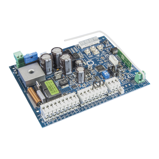
- Seite 1 Manuale per il collegamento e l’uso Connection and operating manual Manuel de raccordement et d’utilisation Manual de instrucciones para la conexión y el uso Anschluss- und Bedienungsanleitung Εγχειρίδιο σύνδεσης και χρήσης PROGRAM. MENU' 25 26 DL11 F2 (ATO) 15 A AP/CH F1 (5x20) F 3.15A...
-
Seite 2: Inhaltsverzeichnis
Indice: Pagina Avvertenze per l’installatore 1 - caratteristiche..........................................1 2 - descrizione della centrale ......................................1 3 - valutazione dei rischi ........................................2 4 - cablaggi elettrici ...........................................2 5 - descrizione led e pulsanti su scheda ...................................7 6 - programmazione rapida ......................................8 7 - programmazione completa ......................................9 diagramma di flusso riassuntivo ....................................15 9 - installazione batterie ........................................17... -
Seite 3: Caratteristiche
1- Caratteristiche Centrale per il comando di motoriduttori scorrevoli a 24 Vdc con potenza nominale di 50 W, prevista con ingressi per finecorsa, encoder (usato per la rilevazione ostacolo e il controllo di velocità) ricevitore integrato e display per la programmazione La centrale permette: di personalizzare lo spazio e la velocità... -
Seite 4: Valutazione Dei Rischi
Valutazione dei rischi prima di iniziare l’installazione dell’automatismo è necessario valutare tutti i possibili punti di pericolo presenti durante la movimentazione del cancello, in Fig.2 vengono evidenziati alcuni dei punti di pericolo del cancello scorrevole. Fig. 2 A - Schiacciamento B - Convogliamento C - Cesoiamento Prima di iniziare l’installazione è... - Seite 5 4.2- Cablaggio lampeggiante, luce di cortesia e spia di segnalazione movimento cancello bianco 24 Vdc 15 W max Motore Uscita alimentazione elettrico accessori 24V dc 300mA 24 Vdc 65 mA max 24 Vdc 65 mA max Fig. 5 Luce di cortesia o spia segnalazione movimento cancello secondo canale radio...
- Seite 6 4.4- Collegamento pulsanti di comando e selettore a chiave Contatti normalmente aperti (i LED rossi AP/CH o APED si accendono quando viene azionato il selettore o i pulsanti collegati in parallelo): Art. EDS1 N.C. N.C. N.O. N.O. comando apertura pedonale comando apertura Fig.
- Seite 7 4.6- Collegamento bordo sensibile o fotocellula interna Con bordo o fotocellula non impegnato il LED STPA deve essere accesso vedi parametro 6. Se non utilizzato fare un ponticello tra COM e STPA. Nel caso sia collegato un bordo sensibile a switch il parametro 6 deve essere settato a 2 e collegando un bordo sensibile resistivo por- tare il parametro 6 a 3 ( l’intervento del bordo durante l’apertura fa invertire il movimento del cancello per circa 10 cm mentre durante la chiusura comanda l’apertura totale).
-
Seite 8: Collegamento Antenna
4.6.3 Collegamento fotocellule con funzione fototest attiva Nel caso venga attivata la funzione fototest (la centrale verifica il funzionamento delle fotocellule, vedi parametro 8), rispettare il seguente collegamento (a ogni partenza del motore la centrale toglie l’alimentazione al trasmettitore della fotocellula per verificare il loro funzionamento): C NC NA STPA come fotocellula interna... -
Seite 9: Descrizione Led E Pulsanti Su Scheda
5- Descrizione dei LED presenti sul circuito: Sigla Descrizione Visualizza la presenza di alimentazione di rete (acceso se presente la tensione di rete) STPA Visualizza lo stato dell’ingresso STPA (morsetto 16), se non impegnato il led verde resta acceso, se non viene utilizzato ponti- cellare tra il morsetto COM e STPA AP/CH Visualizza lo stato dell’ingresso AP/CH (morsetto 11), se non impegnato il led rosso resta spento... -
Seite 10: Programmazione Rapida
6.1- Procedura per la programmazione facilitata del corsa del cancello: Il cancello si porta in posi- Il cancello si chiude Continua la chiusura a zione di completa apertura a velocità ciclo velocità rallentata fino alla e velocità rallentata completa chiusura La centrale memorizza i valori e esce dalla programmazione... -
Seite 11: Programmazione Completa
6.2 Procedura per memorizzare un radiocomando associato al tasto APCH: Premere 2 volte il tasto UP, nel display compare la scritta RAD Premere il tasto OK, nel display compare la scritta 1CH ( indica che il tasto del radiocomando verrà memorizzato come AP/CH della centrale) Premere il tasto OK, nel display compaio 4 pallini, questo indica che la centrale è... - Seite 12 7.1 LRNE: procedura rapida per la programmazione della corsa del cancello Partendo da finecorsa di chiusura impegnato (cancello chiuso), dopo essere entrati in programmazione premendo UP, OK e AP/CH, il cancello parte in aper- tura a velocità rallentata fino all’impegno del finecorsa di apre, dopo 2 secondi il cancello riparte in chiusura a velocità di ciclo e rallenta a circa 50cm della com- pleta chiusura e continua fino all’impegno del finecorsa di chiude, la centrale memorizza la corsa del cancello, con spazi e velocità...
- Seite 13 7.2 RAD: menù gestione radiocomandi si divide in 4 parametri Premendo 1 volta UP Premendo 2 volta UP Premendo 3 volta UP Messaggio Display Descrizione Messaggio Display dopo aver azionato il radiocomando Permette di memorizzare il tasto del radiocomando corrispondente 1 CH 1*** all’ingresso AP/CH...
- Seite 14 N.B.: il primo radiocomando memorizzato configura la centrale per accettare solo i radiocomandi con codifica rolling-code o solo radiocomandi con codifica fissa a 12bit Nel caso sia necessario cancellare tutti i radiocomandi , entrare nel menù RAD, selezionare la voce ALL ( presente tra il numero 001 e 200) pre- mere e tenere premuto il tasto OK per almeno 5 secondi, il display visualizza i 4 pallini per confermare l’operazione.
- Seite 15 7.4 PAR: Permette di modificare tutti i parametri della centrale, premere il tasto OK per visualizzare i parametri,nel display compare la dicitura P01 (parametro numero 1), il tasto UP o DOWN permette di scorrere la lista dei parametri (vedi tabella parametri). Premere il pulsante fino al paramentro da modificare...
- Seite 16 Tabella parametri Numero Valore di Valore parametro Descrizione Valori impostabili defaut modificato Abilita la richiusura automatica ON/OFF Imposta il tempo di richiusura automatica 2-600 secondi 60 secondi Funzionamento ingresso AP/CH 1= durante l’apertura l’ingresso AP/CH non attivo (condominiale) 2=AP/CH come sequenziale ( apre, stop,chiude, stop..) 3=AP/CH come sequenziale (apre,apre,chiude..) Prelampeggio ON/OFF...
-
Seite 17: 8- Diagramma Di Flusso Riassuntivo
N.B: dove avere eseguito la taratura della corsa, se vengono modificati i parametri 11-12-13-14 e 31 dopo la conferma tramite il tasto ENTER nel display compare la scritta APCH , è necessario dare in comando tramite il tasto APCH, il cancello esegue una manovra completa di apertura e di chiusura ( con questa operazione la centrale memorizza le nuove soglie di correnti con le velocità... - Seite 18 Messaggio display Descrizione Nessun allarme memorizzato nella locazione Rilevato un problema su l’uscita che alimentazione del motore Rilevato un ostacolo durante il movimento di apertura Rilevato un ostacolo durante il movimento di chiusura Contatto dell’ingresso FOTO aperto Si è verificata una condizione che ha portato all’arresto del motore Contatto dell’ingresso STPA.
-
Seite 19: Installazione Batterie
9-Diagramma di flusso riassuntivo: Programmazione Programmazione rapida rapida AP/CH Memorizzare il Memorizzare radiocomando il radiocomando APCH come APCH Max 200 Memorizzare il Memorizzare il radiocomando radiocomando come secondo come secondo canale radio canale audio Visualizzazione Visualizzazione locazione di locazione di memoria memoria radiocomando... -
Seite 20: Problemi E Soluzioni
- Controllo non attivo - Controllo su ingresso FOTO Test fotocellula - Controllo su ingresso STPA - Controllo su ingresso STPA e FOTO Spazio di rallentamento 0 ÷ 536 cm chiusura Spazio di rallentamento 0 ÷ 536 cm apertura Velocità di ciclo 50 ÷... -
Seite 21: 11- Parametri Programmabili
0 - Funziona normalmente 1 - Dopo un comando il cancello si apre Con batteria l’automazione e resta aperto resta aperta 2 - Il cancello sia apre e resta aperto 0 - Funzione non attiva 1 - Funzione attiva solo con sicurezze aperte e solo con gli ingressi APCH Funzione uomo presente e PED... -
Seite 22: Problemi E Soluzioni
10-INSTALLAZIONE BATTERIE inserire nel connettore battery card il circuito di carica batteria e collegare le batterie al circuito, con il funzionamento a batteria la velocità del motore è 15% inferiore rispetto la velocità con alimentazione di rete, il numero di manovre con le batterie dipende da il numero di fotocellule presenti nell’impianto e della lunghezza del cancello. - Seite 23 Associazione radiocomandi nomi utenti: N. memoria Utente N. memoria Utente N. memoria Utente...
-
Seite 24: Dichiarazione Ce Di Conformità
DICHIARAZIONE CE DI CONFORMITÀ (Dichiarazione di incorporazione di quasi-macchine allegato IIB Direttiva 2006/42/CE) No.:ZDT00434.00 Il sottoscritto, rappresentante il seguente costruttore Elvox SpA Via Pontarola, 14/A - 35011 Campodarsego (PD) Italy dichiara qui di seguito che i prodotti SCHEDA DI COMANDO - SERIE RS Articoli RS1, RS2, RS3, RS4, RS5, RS6, RS7, RS8, RS12, RS13, RS14 risultano in conformità... - Seite 25 NOTE:...
-
Seite 26: Warnings For The Installer
Contents: Page Warnings for the installer 1 - characteristics..........................................25 2 - description of the control panel ....................................25 3 - risk assessment ...........................................26 4 - electrical wiring harnesses ......................................26 5 - description of LEDs and buttons on board ..................................31 6 - quick programming ........................................31 7 - complete programming ........................................33 summary flowchart ........................................41 9 - installing batteries ........................................44... -
Seite 27: Characteristics
1- Characteristics Control panel for governing sliding gear motors, 24 V dc with 50 W rated power, equipped with inputs for limit switch, encoder (used for obstacle detection and speed control) integrated receiver and display for programming The control panel enables: customizing the space and speed of deceleration in both opening and closing phases equipped with obstacle detection system LED for input diagnostics... -
Seite 28: Risk Assessment
Risk assessment Before starting to install the automatic gate system it is necessary to evaluate all possible points of danger during the movement of the gate. Fig.2 shows some of the danger points of the sliding gate. Fig. 2 A - Crushing B - Conveying C - Shearing Before starting installation you need to check that the gate slides properly, that there are secure mechanical stops and check the gate support system. - Seite 29 4.2- Wiring for flashing light, courtesy light and gate movement warning light white 24 Vdc 15 W max Electric Accessories power supply motor output 24V dc 300mA 24 Vdc 65 mA max 24 Vdc 65 mA max Fig. 5 Courtesy light or gate movement warning light...
-
Seite 30: Connecting Photocells
4.4- Connecting control buttons and key switch Normally open contacts (the red AP/CH or APED LEDS light up when the selector or buttons connected in parallel are operated): Art. EDS1 N.C. N.C. N.O. N.O. pedestrian opening control opening control Fig. 6 4.5- Connecting photocells Normally closed contact (when the photocells are not engaged the PHOTO LED must be on), if not used then jumper between COM. - Seite 31 4.6- Connecting sensitive edge or internal photocell With edge or photocell not engaged the STPA LED must be on, see parameter 6. If not used, jumper between COM and STPA. If a switch sensitive edge is connected, parameter 6 must be set to 2 and when connecting a resistive sensitive edge set parameter 6 to 3 (the edge tripping during opening reverses the movement of the gate by approximately 10 cm whereas during closing it causes total opening).
-
Seite 32: Connecting The Aerial
4.6.3 Connecting photocells with photo-test function active If the photo-test function is activated (the control unit checks the operation of the photocells, see parameter 8), respect the following connection (each time the motor starts the control unit cuts off power to the transmitter of the photocell to check their operation): C NC NA STPA as Safety come... -
Seite 33: Description Of The Leds In The Circuit
5- Description of the LEDS in the circuit: Abbreviation Description Shows whether there is mains power (lit if there is mains voltage) STPA Displays the status of the STPA input (terminal 16), if not engaged the green LED remains lit, if not used then jumper between terminal COM and STPA AP/CH Displays the status of the AP/CH input (terminal 11), if not engaged the red LED remains off... - Seite 34 6.1- Procedure for facilitated gate travel programming: CLOSING The gate goes into the fully The gate closes Continues closing at re- open position and slow at cycle speed duced speed until complete- speed ly closed The control panel saves the values and exits the programming mode Starting with the closing limit switch engaged (gate closed), after entering programming mode by pressing the UP, OK, and AP/CH button, the gate starts...
-
Seite 35: Complete Programming
6.2 Procedure for saving a remote control associated with button APCH: Press the UP button 2 times, the display will show RAD Press the OK button, the display will show 1CH (indicating that the remote control button will be saved as AP/CH of the control panel) Press the OK button, 4 dots will appear on the display, indicating that the control panel is waiting for a remote control button to be tapped (timeout 10 seconds) After pressing the remote control button the display will show a 4-digit number: the first digit indicates association (1 controls the AP/CH input 2 controls the pedestrian entrance or the second channel output) the other 3 indicate the memory cell occupied by the remote control (the first remote control occupies cell 001, the second one... - Seite 36 7.1 LRNE: quick procedure for programming gate travel CLOSING Starting with the closing limit switch engaged (gate closed), after entering programming mode by pressing the UP, OK, and AP/CH button, the gate starts opening at reduced speed until the opening limit switch is engaged. After 2 seconds the gate starts closing at cycle speed and slows down approximately 50cm from being completely closed and continues until the closing limit switch is engaged.
- Seite 37 7.2 RAD: remote control management menu is divided into 4 parameters: Pressing UP 1 time Pressing UP 2 time Pressing UP 3 time Display Message Description Display message after activating the remote control Used to save the remote control button corresponding to the input 1 CH 1*** AP/CH...
- Seite 38 N.B.: The first saved remote control configures the control panel to accept only remote controls with a rolling code or only remote controls with a fixed 12-bit code If you need to delete all the remote controls, enter the RAD menu, select ALL (between number 001 and 200), press and hold the OK button for 5 at least seconds, and the display will show the 4 dots confirming the operation.
- Seite 39 7.4 PAR: Used to modify all the parameters of the control unit, press the OK button to display the list of parameters, the display will show P01 (parameter number 1), the UP or DOWN button lets you scroll through the list of parameters (see parameter table). Press the button until you see the parameter to be modified...
- Seite 40 Parameter table Parameter Default Modified number Description Settable values value value Enables automatic closing ON/OFF Sets the automatic closing time 2-600 seconds 60 seconds AP/CH input operation 1= when opening, AP/CH input not active (condo) 2=AP/CH as sequential (open, stop, close, stop..) 3=AP/CH as sequential (open, open, close..) Pre-flash ON/OFF...
- Seite 41 N.B.: After calibrating the travel, if parameters 11-12-13-14 and 31 are changed after confirming with the ENTER key the display reads APCH, you must give the command by pressing the APCH button, the gate will perform a complete opening and closing cycle (with this operation, the control unit saves the new current thresholds with the modified speeds) 7.5 DEF: used to set the control panel on the default parameters except for parameters 9-10-11-12-14-15-22-23-24-26-31, press and release the OK button,...
- Seite 42 Display message Description No alarm saved in the location Detected a problem on the output powering the motor Detected an obstacle during the opening movement Detected an obstacle during the closing movement PHOTO input contact open A condition has occurred causing the motor to stop STPA input contact open External memory damaged The encoder input is not read correctly or there is no connection between the control panel and the encoder...
-
Seite 43: 8-Summary Flowchart
8-Summary flowchart: Quick program- Programmazione ming rapida AP/CH Save the Memorizzare remote control il radiocomando APCH come APCH Max 200 Save the re- Memorizzare il mote control as radiocomando come secondo a second radio channel canale audio Viewing Visualizzazione memory loca- locazione di tion memoria... - Seite 44 0 - Check not active - Controllo non attivo 1 - Check on PHOTO input Photocell test - Controllo su ingresso FOTO 2 - Check on STPA input Test fotocellula - Controllo su ingresso STPA 3 - Check on STPA and PHOTO input - Controllo su ingresso STPA e FOTO Slowdown distance when Spazio di rallentamento...
-
Seite 45: Reset Counter
0 - Operates normally 0 - Funziona normalmente 1 - After a command, the gate opens With battery the automation 1 - Dopo un comando il cancello si apre Con batteria l’automazione and stays open remains open e resta aperto resta aperta 2 - The gate opens and remains open 2 - Il cancello sia apre e resta aperto... -
Seite 46: Installing Batteries
9- Installing batteries insert the battery charging circuit in the battery card connector and connect the batteries to the circuit, with battery operation the speed of the motor is 15% lower than the speed with mains power, the number of operations with the batteries depends on the number of photocells in the system and the length of the gate. -
Seite 47: 12- User Name Remote Control Association
12- User name remote control association: Memory no. User Memory no. User Memory no. User 45 45... -
Seite 48: Ec Declaration Of Conformity
EC DECLARATION OF CONFORMITY (Declaration of incorporation of partly completed machinery Annex IIB Directive 2006/42/EC) No.:ZDT00434.00 The undersigned, representing the following manufacturer Elvox SpA Via Pontarola, 14/A - 35011 Campodarsego (PD) Italy herewith declares that the products CONTROL BOARD - RS SERIES Articles RS1, RS2, RS3, RS4, RS5, RS6, RS7, RS8, RS12, RS13, RS14 are in conformity with the provisions of the following EU Directive(s) (including all applicable amendments) and that all of the... - Seite 49 NOTES:...
-
Seite 50: Recommandations Pour L'installateur
Index Page Recommandations pour l’installateur 1 - caractéristiques ...........................................49 2 - description de la centrale ......................................49 3 - évaluation des risques .........................................50 4 - câblages électriques ........................................50 5 - description des leds et des boutons sur la carte .................................55 6 - programmation rapide .........................................55 7 - programmation complète ......................................57 8 - diagramme de flux récapitulatif ....................................65 9 - installation des batteries ......................................68... -
Seite 51: Caractéristiques
1- Caractéristiques Centrale de commande pour motoréducteurs coulissants 24 Vcc, puissance nominale 50 W, avec entrées pour fin de course, codeur (pour la détection des obstacles et le contrôle de la vitesse), récepteur intégré et afficheur pour la programmation La centrale permet : de personnaliser l'espace et la vitesse de ralentissement en ouverture et en fermeture elle est équipée d'un système de reconnaissance des obstacles led pour le diagnostic des entrées... -
Seite 52: Évaluation Des Risques
Évaluation des risques Avant de commencer l'installation de l'automatisme, évaluer les points de danger potentiels liés au mouvement du portail (la fig.2 montre quelques-uns des points de danger du portail coulissant). Fig. 2 A - Écrasement B - Convoyage C - Cisaillement Avant de commencer l'installation, vérifier le coulissement du portail, la présence des arrêts mécaniques, leur état et le système de soutien du portail. - Seite 53 4.2 - Câblage clignotant, éclairage de courtoisie et voyant de signalisation du mouvement du portail blanc 24 Vcc, 15 W max Moteur Sortie alimentation électrique accessoires 24 Vcc 300 mA 24 Vcc, 65 mA max 24 Vcc, 65 mA max Fig.
- Seite 54 4.4- Connexion des boutons de commande et du sélecteur à clé Contacts normalement ouverts (les LEDS rouges APCH ou APED s'allument quand le sélecteur ou les boutons reliés en parallèle sont actionnés) : Art. EDS1 N.C. N.C. N.O. N.O. commande ouverture piétons commande ouverture Fig.
- Seite 55 4.6 - Connexion bord sensible ou cellule photoélectrique interne Si le bord ou la cellule photoélectrique ne sont pas actifs, la led STPA doit être allumée ; voir paramètre 6. Si elle n'est pas utilisée, faire un shunt entre COM et STPA. Si un bord sensible est relié à un switch, régler le paramètre 6 sur 2 et amener le paramètre 6 sur 3 en reliant un bord sensible (l'in- tervention du bord durant l'ouverture fait inverser le mouvement du portail sur 10 cm environ alors qu'il commande l'ouverture totale durant la fermeture).
-
Seite 56: Connexion De L'antenne
4.6.3 Connexion cellules photoélectriques avec fonction phototest active Si la fonction phototest est active (la centrale vérifie le fonctionnement des cellules photoélectriques, voir paramètre 8) ; respecter les liaisons suivantes (à chaque démarrage du moteur, la centrale coupe l'alimentation du transmetteur de la cellule photoélectrique pour vérifier son fonctionnement) : C NC NA STPA comme Safety come... -
Seite 57: Description Des Leds Et Des Boutons Sur La Carte
5 - Description des LEDS du circuit Sigle Description Affiche l'alimentation du réseau (allumée si la tension du réseau est présente). STPA Affiche l'état de l'entrée STPA (borne 16) ; si elle n'est pas active, la led verte reste allumée ; si elle n'est pas utilisée, faire un shunt entre les bornes COM et STPA. - Seite 58 6.1- Procédure de programmation facilitée de la course du portail : FERMETURE Le portail s’ouvre Le portail se ferme La fermeture au ralenti complètement au ralenti à la vitesse de cycle continue jusqu'à la fermeture complète La centrale mémorise les valeurs et quitte la programmation En condition de fin de course de fermeture actif (portail fermé), après avoir accédé...
-
Seite 59: Menu Principal
6.2 Procédure pour enregistrer une radiocommande associée à la touche APCH : Appuyer 2 fois sur la touche UP, l'afficheur visualise RAD Appuyer sur OK, l'afficheur visualise 1CH (indique que la touche de la radiocommande sera enregistrée comme AP/CH de la centrale). Appuyer sur OK, l'afficheur visualise 4 points pour indiquer que la centrale est en attente que l'on appuie sur une touche de la radiocommande (temps maxi 10 secondes). - Seite 60 7.1 LRNE : procédure rapide de programmation de la course du portail FERMETURE En condition de fin de course de fermeture actif (portail fermé), après avoir accédé à la programmation en appuyant sur UP, OK et AP/CH, le portail s'ouvre au ralenti jusqu'à...
- Seite 61 7.2 RAD : menu de gestion des radiocommandes comptant 4 paramètres En appuyant 1 fois sur UP En appuyant 2 fois sur UP En appuyant 3 fois sur UP Message Afficheur Description Message Afficheur après avoir actionné la radiocommande Permet d'enregistrer la touche de la radiocommande correspon- 1 CH 1*** dant à...
- Seite 62 N.B. : la première radiocommande enregistrée configure la centrale pour qu'elle accepte uniquement les radiocommandes avec code tournant ou fixe 12 bits. S'il s'avère nécessaire d'effacer toutes les radiocommandes, entrer dans le menu RAD, sélectionner ALL (rubrique présente entre les numéros 001 et 200), appuyer et garder le doigt au moins 5 secondes sur OK, l'afficheur visualise 4 points pour confirmer l’opération.
- Seite 63 7.4 PAR : Permet de modifier tous les paramètres de la centrale, appuyer sur OK pour afficher les paramètres, l'afficheur visualise P01 (paramètre numéro 1), la touche UP ou DOWN permet de parcourir la liste des paramètres (voir tableau des paramètres). Appuyer sur le bouton jusqu'à...
- Seite 64 Tableau des paramètres Numéro Valeur Valeur paramètre Description Valeurs possibles d'usine modifiée Valide la refermeture automatique ON/OFF Définit le temps de refermeture automatique 2-600 secondes 60 secondes Fonctionnement entrée AP/CH 1= durant l'ouverture, l'entrée AP/CH n'est pas validée (co-propriété) 2=AP/CH comme séquentielle (ouvre, stop, ferme, stop..) 3=AP/CH comme séquentielle (ouvre, ouvre, ferme..) Pré-clignotement ON/OFF...
- Seite 65 N.B : après avoir réglé la course, si l'on modifie les paramètres 11-12-13-14 et 31 après avoir confirmé en appuyant sur ENTER, l'afficheur visualise APCH ; lancer une commande à travers la touche APCH, le portail accomplit une manœuvre complète d'ouverture et de fermeture (avec cette opération, la centrale mémorise les nouveaux seuils de courant avec les vitesses modifiées) 7.5 DEF : permet de régler la centrale sur les paramètres d'usine à...
- Seite 66 Message Afficheur Description Aucune alarme mémorisée sur la position Problème détecté sur la sortie d'alimentation du moteur Obstacle détecté durant l'actionnement en ouverture Obstacle détecté durant l'actionnement en fermeture Contact de l’entrée FOTO ouvert Condition ayant déterminé l'arrêt du moteur Contact de l’entrée STPA ouvert Mémoire extérieure endommagée L'entrée codeur n'est pas lue correctement ou connexion entre centrale et codeur absente...
-
Seite 67: Diagramme De Flux Récapitulatif
8-Diagramme de flux récapitulatif : Programmation Programmazione rapide rapida AP/CH Enregistrer Memorizzare la radiocom- il radiocomando mande APCH come APCH Max 200 Enregistrer la Memorizzare il radiocommande radiocomando comme deuxième come secondo canal radio canale audio Affichage Visualizzazione emplacement de locazione di mémoire memoria... - Seite 68 0 - Contrôle non actif - Controllo non attivo 1 - Contrôle sur entrée FOTO Test cellule photoélectrique - Controllo su ingresso FOTO 2 - Contrôle sur entrée STPA Test fotocellula - Controllo su ingresso STPA 3 - Contrôle sur entrée STPA et FOTO - Controllo su ingresso STPA e FOTO Espace de ralentissement Spazio di rallentamento...
- Seite 69 0 - Fonctionne normalement 0 - Funziona normalmente 1 - Après une commande, le portail Avec la batterie, l’automation 1 - Dopo un comando il cancello si apre Con batteria l’automazione s’ouvre et reste ouvert reste ouverte e resta aperto resta aperta 2 - Le portail s’ouvre et reste ouvert 2 - Il cancello sia apre e resta aperto...
-
Seite 70: Installation Des Batteries
9 - Installation des batteries Introduire dans le connecteur « battery card » le circuit du chargeur de batterie et brancher les batteries au circuit ; lorsqu'il fonctionne seulement sur la bat- terie, la vitesse du moteur est réduite de 15 % par rapport à l'alimentation par le réseau ; le nombre de manœuvres avec les batteries dépend du nombre de cellules photoélectriques dans le circuit et de la longueur du portail. -
Seite 71: 12- Association Radiocommandes / Noms Usagers
12- Association radiocommandes / noms usagers : N. mémoire Utilisateur N. mémoire Utilisateur N. mémoire Utilisateur 69 69... -
Seite 72: Déclaration De Conformité
DÉCLARATION DE CONFORMITÉ (Déclaration d'intégration de quasi-machines annexe IIB Directive 2006/42/CE) N° : ZDT00434.00 Je soussigné, représentant le fabricant Elvox SpA Via Pontarola, 14/A - 35011 Campodarsego (PD) Italy déclare ci-dessous que les produits : CARTE DE COMMANDE - SÉRIE RS articles RS1, RS2, RS3, RS4, RS5, RS6, RS7, RS8, RS12, RS13, RS14 sont conformes aux directives communautaires suivantes (ainsi qu'à... - Seite 73 REMARQUE :...
- Seite 74 Índice: Página Advertencias para el instalador 1- Características ..........................................73 2 - Descripción de la central ......................................73 3 - Evaluación de riesgos .........................................74 4 - Cableados eléctricos ........................................74 5 - Descripción de leds y pulsadores en la tarjeta ................................79 6 - Programación rápida ........................................79 7 - Programación completa ......................................81 Diagrama de flujo sinóptico ......................................89 9 - Montaje de baterías ........................................92...
-
Seite 75: 1- Características
1- Características Central para el control de motorreductores para cancelas correderas de 24 Vcc con potencia nominal de 50 W, provista de entradas para fines de carrera, encoder (utilizado para la detección de obstáculos y el control de la velocidad), receptor integrado y pantalla para la programación. La central: - permite personalizar el espacio y la velocidad de desaceleración para abrir y cerrar - está... -
Seite 76: Evaluación De Riesgos
Evaluación de riesgos Antes de empezar a montar el automatismo, es necesario evaluar todos los posibles puntos de peligro durante la maniobra de la cancela: en la Fig. 2 se indican algunos puntos de peligro de la cancela corredera. Fig. 2 A - Aplastamiento B - Arrastre C - Cizallamiento... - Seite 77 4.2- Cableado de luz rotativa, luz de cortesía y piloto de señalización del movimiento de la cancela blanco 24 Vcc 15 W máx Motor Salida alimentación eléctrico accesorios 24 Vcc 300 mA 24 Vcc 65 mA máx 24 Vcc 65 mA máx Fig.
- Seite 78 4.4- Conexión de pulsadores de mando y selector de llave Contactos normalmente abiertos (los LEDS rojos AP/CH (APERTURA/CIERRE) o APED (APERTURA PEATONAL) se encienden al accionar el selector o los pulsadores conectados en paralelo): Art. EDS1 N.C. N.C. N.O. N.O. mando de apertura peatonal mando de apertura Fig.
- Seite 79 4.6- Conexión del borde sensible o de la fotocélula interna Cuando el borde sensible o la fotocélula están libres, el led STPA debe estar encendido, véase el parámetro 6. Si no se utiliza, puentee COM y STPA. Si se conecta un borde sensible a un interruptor, el parámetro 6 debe configurarse a 2, y si el borde sensible es resistivo, el parámetro 6 debe configurarse a 3 (la actuación del borde durante la apertura hace invertir el movimiento de la cancela unos 10 cm, mientras que durante el cierre acciona la apertura total).
- Seite 80 4.6.3 Conexión de las fotocélulas con función Fototest activada Si se activa la función Fototest (la central comprueba el funcionamiento de las fotocélulas, véase el parámetro 8), respete la siguiente conexión (cada vez que el motor se pone en marcha, la central interrumpe la alimentación al transmisor de la fotocélula para comprobar su funcionamiento): C NC NA STPA como fotocélula interna...
-
Seite 81: Descripción De Leds Y Pulsadores En La Tarjeta
5 - Descripción de los LEDS del circuito: Sigla Descripción Muestra la presencia de alimentación de red (está encendido si hay tensión de red). STPA Muestra el estado de la entrada STPA (borne 16): si no está ocupada, el led verde está encendido y, si no se utiliza, hay que puentear los bornes COM y STPA. - Seite 82 6.1- Procedimiento para la programación simplificada de la carrera de la cancela: CIERRE La cancela llega a la posición La cancela se cierra Continúa el cierre a velocidad de apertura total a velocidad a velocidad de ciclo desacelerada hasta el cierre desacelerada total La central guarda los valores...
-
Seite 83: Programación Completa
6.2- Procedimiento para memorizar un mando a distancia asociado a la tecla APCH: Pulse 2 veces la tecla UP, en pantalla aparece RAD Pulse la tecla OK, en pantalla aparece 1CH (indica que la tecla del mando a distancia se va a memorizar como AP/CH de la central). Pulse la tecla OK, en pantalla aparecen 4 puntos para indicar que la central está... - Seite 84 7.1 LRNE: procedimiento rápido para la programación de la carrera de la cancela CIERRE Comenzando con el fin de carrera de cierre ocupado (cancela cerrada), después de entrar en la programación pulsando UP , OK y AP/CH, la cancela se va abriendo a velocidad ralentizada hasta alcanzar el tope de apertura;...
- Seite 85 7.2 RAD: el menú de gestión de mandos a distancia consta de 4 parámetros: Pulsando 1 vez UP Pulsando 2 veces UP Pulsando 3 veces UP Mensaje en pan- Mensaje en pantalla después de accionar el mando a dis- Descripción talla tancia Permite memorizar la tecla del mando a distancia correspondiente...
- Seite 86 Nota: el primer mando a distancia memorizado configura la central para aceptar solo los mandos a distancia con codificación rolling code o solo mandos a distancia con codificación fija de 12 bits. Si fuera necesario borrar todos los mandos a distancia, entre en el menú RAD, seleccione ALL (que se encuentra entre el número 001 y 200), pulse y mantenga pulsada la tecla OK durante al menos 5 segundos: en pantalla aparecen 4 puntos para confirmar la operación.
- Seite 87 7.4 PAR: Permite modificar todos los parámetros de la central: pulse la tecla OK para ver los parámetros y en pantalla aparece P01 (parámetro número 1); con la tecla UP o DOWN es posible desplazarse por la lista de parámetros (consulte la tabla de parámetros). Pulse la tecla hasta el pará- metro a modificar...
-
Seite 88: Tabla De Parámetros
Tabla de parámetros Número Valor por Valor parámetro Descripción Valores configurables defecto modificado Habilita el cierre automático ON/OFF 60 segun- Configura el tiempo de cierre automático 2-600 segundos 1= durante la apertura la entrada AP/CH no está activada (comunidad de Funcionamiento de la entrada AP/CH vecinos) 2=AP/CH como secuencial (abre, para, cierra, para..) - Seite 89 Nota: después de realizar la calibración de la carrera, si se modifican los parámetros 11-12-13-14 y 31, después de la confirmación con la tecla ENTER, en pantalla aparece APCH y es necesario accionar la tecla APCH: la cancela realiza una maniobra completa de apertura y cierre (con esta operación la central guarda los nuevos umbrales de corriente con las velocidades modificadas).
- Seite 90 Mensaje en pantalla Descripción Ninguna alarma memorizada Fallo en la salida que alimenta el motor Se ha detectado un obstáculo durante el movimiento de apertura Se ha detectado un obstáculo durante el movimiento de cierre Contacto de la entrada FOTO abierto Se ha producido una situación que ha conllevado la parada del motor Contacto de la entrada STPA abierto Memoria externa dañada...
-
Seite 91: 8- Diagrama De Flujo Sinóptico
8- Diagrama de flujo sinóptico: Programación Programmazione rápida rapida AP/CH Memorización Memorizzare del mando a il radiocomando distancia APCH come APCH Max 200 Memorización Memorizzare il del mando a radiocomando distancia como come secondo segundo canal de canale audio radio Visualización Visualizzazione ubicación de... - Seite 92 0 - Control no activado - Controllo non attivo 1 - Control de la entrada FOTO Prueba de fotocélula - Controllo su ingresso FOTO 2 - Control de la entrada STPA Test fotocellula - Controllo su ingresso STPA 3 - Control de la entrada STPA y FOTO - Controllo su ingresso STPA e FOTO Espacio de desaceleración Spazio di rallentamento...
- Seite 93 0 - Funciona normalmente 0 - Funziona normalmente 1 - Después de una orden la cancela se Con batería la automatiza- 1 - Dopo un comando il cancello si apre Con batteria l’automazione abre y permanece abierta ción permanece abierta 2 - La cancela se abre y permanece e resta aperto resta aperta...
-
Seite 94: Montaje De Baterías
9- Montaje de las baterías Introduzca el circuito del cargador en el conector de la tarjeta de las baterías y conecte las baterías: con el funcionamiento a batería, la velocidad del motor es un 15% inferior respecto a la velocidad con alimentación de red, el número de maniobras con baterías depende del número de fotocélulas en la instalación y de la longitud de la cancela. -
Seite 95: Asociación De Mandos A Distancia Con Nombres De Usuarios
12-Asociación de mandos a distancia con nombres de usuarios: N. memoria Usuario N. memoria Usuario N. memoria Usuario 93 93... -
Seite 96: Declaración Ce De Conformidad
DECLARACIÓN CE DE CONFORMIDAD (Declaración de incorporación de cuasi máquinas, anexo IIB Directiva 2006/42/CE) N. ZDT00434.00 El abajo firmante, representante del siguiente fabricante Elvox SpA Via Pontarola, 14/A - 35011 Campodarsego (PD) Italia declara que los productos TARJETA DE MANDO - SERIE RS Artículos RS1, RS2, RS3, RS4, RS5, RS6, RS7, RS8, RS12, RS13, RS14 son conformes a lo que establecen las siguientes directivas comunitarias (incluidas todas las modificaciones aplicables) y que... - Seite 97 NOTAS:...
- Seite 98 Inhalt: Seite Hinweise für den Installationstechniker 1- Merkmale .............................................97 2 - Beschreibung des Steuergeräts ....................................97 3 - Risikobewertung ..........................................98 4- Verkabelung ..........................................98 5 - Beschreibung der LEDs und Tasten auf der Leiterplatte .............................103 6 - Schnelle Programmierung ......................................103 7 - Ausführliche Programmierung .....................................105 8 - Ablaufübersicht ..........................................113 9- Installation der Batterien ......................................116 10 - Störungen und Abhilfen .......................................116...
-
Seite 99: 1- Merkmale
1- Merkmale Steuergerät 24 Vdc für Schiebetorantriebe mit Nennleistung 50 W, ausgestattet mit Eingängen für Anschläge, Encoder (zur Erfassung von Hindernissen und Geschwindigkeitsregelung), integriertem Empfänger und Display für die Programmierung Funktionen und Ausstattung des Steuergeräts: Individuelle Einstellung von Bremsweg und -geschwindigkeit beim Öffnen sowie Schließen System zur Hinderniserkennung Diagnose-LED der Eingänge Abnehmbarer Datenspeicher... -
Seite 100: Risikobewertung
Risikobewertung Vor Installation des Antriebs müssen alle möglichen Gefahrenstellen während der Bewegung des Tors bewertet werden, die Abb.2 zeigt einige Gefah- renstellen an einem Schiebetor. Abb. 2 A - Quetschung B - Mitreißen C - Scherung Vor der Installation den leichtgängigen Torlauf, den Einbau und die Robustheit der mechanischen Anschläge sowie die Stützsysteme des Tors überprüfen. Verkabelung 2 x 1 mm 3 x 0,5 mm... -
Seite 101: Funktion
4.2- Verkabelung von Blinkleuchte, Komfortbeleuchtung und Anzeigelampe der Torbewegung Weiß 24 Vdc 15 W max. Elektro- Ausgang für Motor Zubehörversorgung 24Vdc 300mA 24 Vdc 65 mA max. 24 Vdc 65 mA max. Abb. 5 Anzeigelampe der Servicebeleuchtung oder zweiter Funkkanal Torbewegung HINWEIS: Die Verkabelung des Motorausgangs (Klemme 1 und 2) nicht verändern, da der Dip-Schalter 2-2 die Öffnungsrichtung auswählt. -
Seite 102: Anschluss Der Lichtschranken
4.4- Anschluss der Steuertasten und des Schlüsselschalters Arbeitskontakte (die roten LEDS AP/CH oder APED leuchten bei Betätigung des Schlüsselschalters bzw. der parallel geschalteten Tasten auf): Art. EDS1 N.C. N.C. N.O. N.O. Steuerung der Fußgänger-Öffnung Öffnungssteuerung Abb. 6 4.5- Anschluss der Lichtschranken Ruhekontakt (bei nicht aktivierten Lichtschranken muss die LED FOTO erleuchtet sein), sofern nicht verwendet, eine Schaltbrücke zwischen COM. -
Seite 103: Anschluss Der Resistiven Kontaktleiste
4.6- Anschluss der Kontaktleiste oder internen Lichtschranke Bei nicht aktivierter Kontaktleiste bzw. Lichtschranke muss die LED STPA erleuchtet sein, siehe Parameter 6. Sofern nicht verwendet, eine Schaltbrücke zwi- schen COM und STPA einfügen. Bei Anschluss einer Kontaktleiste an Schalter muss der Parameter 6 auf 2, beim Anschließen einer resistiven Kontaktleiste muss der Parameter 6 auf 3 gesetzt sein (die Auslösung der Kontaktleiste beim Öffnen kehrt die Torbewegung um ca. -
Seite 104: Anschluss Der Stopptaste
4.6.3 Anschluss der Lichtschranken mit aktiver Fototest-Funktion Bei Aktivierung der Fototest-Funktion (das Steuergerät prüft den Betrieb der Lichtschranken, siehe Parameter 8) folgenden Anschluss beachten (bei jedem Motorstart unterbricht das Steuergerät die Versorgung zum Sender der Lichtschranke, um die Funktion nachzuweisen): C NC NA STPA als Safety come... -
Seite 105: Beschreibung Der Leds Im Schaltkreis
5- Beschreibung der LEDS im Schaltkreis: Kürzel Beschreibung Zeigt das Anliegen von Netzspannung an (bei anliegender Netzspannung erleuchtet) STPA Zeigt den Status des Eingangs STPA an (Klemme 16), sofern nicht aktiviert, bleibt die grüne LED erleuchtet, sofern nicht ver- wendet, eine Schaltbrücke zwischen der Klemme COM und STPA einfügen AP/CH Zeigt den Status des Eingangs AP/CH (Klemme 11) an, sofern nicht aktiviert, bleibt die rote LED erloschen APED... -
Seite 106: Verfahren Zur Einfachen Programmierung Des Torlaufs
6.1- Verfahren zur einfachen Programmierung des Torlaufs: SCHLIESSEN Das Tor öffnet vollständig Das Tor schließt Das Schließen mit abgebrem- mit abgebremster ster Geschwindigkeit wird bis Geschwindigkeit Zyklusgeschwindigkeit zur vollständigen Schließung fortgesetzt Das Steuergerät speichert die Werte und beendet die Programmierung Ausgehend von beschaltetem Schließanschlag (Tor geschlossen) startet das Tor nach Aufrufen der Programmierung durch Drücken der Tasten UP, OK und AP/CH in Öffnungsbewegung mit abgebremster Geschwindigkeit bis zum Auslösen des Öffnungsanschlags, startet nach 2 Sekunden in Schließbewegung mit Zyklusgeschwindigkeit, bremst ca. -
Seite 107: Verfahren Zum Speichern Einer Der Taste Apch Zugewiesenen Funkfernsteuerung
6.2 Verfahren zum Speichern einer der Taste APCH zugewiesenen Funkfernsteuerung: Die Taste UP 2 Mal drücken, am Display erscheint der Eintrag RAD Die Taste OK drücken, am Display erscheint der Eintrag 1CH (als Hinweis darauf, dass die Taste der Funkfernsteuerung als AP/CH des Steuergeräts gespeichert wird). - Seite 108 7.1 LRNE: Verfahren zur schnellen Programmierung des Torlaufs SCHLIESSEN Ausgehend von beschaltetem Schließanschlag (Tor geschlossen) startet das Tor nach Aufrufen der Programmierung durch Drücken der Tasten UP, OK und AP/CH in Öffnungsbewegung mit abgebremster Geschwindigkeit bis zum Auslösen des Öffnungsanschlags, startet nach 2 Sekunden in Schließbewegung mit Zyklusgeschwindigkeit, bremst ca.
- Seite 109 7.2 RAD: Das Menü für die Verwaltung der Funkfernsteuerungen ist in 4 Parameter gegliedert 1-maligem Druck von UP 2-maligem Druck von UP 3-maligem Druck von UP Displaymeldung Beschreibung Displaymeldung nach Betätigung der Funkfernsteuerung Speicherung der dem Eingang AP/CH entsprechenden Taste der 1 CH 1*** Funkfernsteuerung...
- Seite 110 HINWEIS: Die erste gespeicherte Funkfernsteuerung konfiguriert das Steuergerät dahingehend, entweder nur Funkfernsteuerungen mit Rolling- code oder mit festem 12Bit Code zu erkennen Zum Löschen sämtlicher Funkfernsteuerungen das Menü RAD aufrufen, die Option ALL (im Intervall 001 bis 200) wählen, die Taste OK mindestens 5 Sekunden lang drücken, am Display erscheinen 4 Pünktchen zur Bestätigung des Vorgangs.
- Seite 111 7.4 PAR: Hiermit können alle Parameter des Steuergeräts geändert werden; mit Taste OK die Liste der Parameter aufrufen, am Display erscheint der Eintrag P01 (Parameter Nummer 1), mit der Taste UP oder DOWN kann die Liste der Parameter gescrollt werden (siehe Parametertabelle). Die Taste bis zum Aufrufen des zu ändernden Parame- ters drücken...
-
Seite 112: Beschreibung
Parametertabelle Nummer Standard- Geänderter Parameter Beschreibung Einstellbare Werte Wert Wert Aktiviert das automatische Schließen ON/OFF 60 Sekun- Stellt die Zeit für automatisches Schließen ein 2-600 Sekunden 1= während der Öffnung ist der Eingang AP/CH nicht aktiviert (Mehrfamili- Funktionsweise Eingang AP/CH enhaus) 2=AP/CH als sequenzieller Eingang (Öffnen, Stopp, Schließen, Stopp..) 3=AP/CH als sequenzieller Eingang (Öffnen, Öffnen, Schließen..) - Seite 113 HINWEIS: Werden nach Einstellung des Torlaufs die Parameter 11-12-13-14 und 31 geändert, erscheint bei Bestätigung mit Taste ENTER am Display der Eintrag APCH, mit Taste APCH muss nun ein Steuerbefehl ausgelöst werden. Das Tor führt eine vollständige Öffnungs- und Schließbewegung aus (hiermit speichert das Steuergerät die neuen Stromschwellen mit den geänderten Geschwindigkeiten) 7.5 DEF: hiermit können die Werksparameter des Steuergeräts wiederhergestellt werden, mit Ausnahme der Parameter 9-10-11-12-14-15-22-23-24-26-31, die Taste OK drücken und loslassen, am Display erscheinen 4 Pünktchen zur Bestätigung des Vorgangs.
-
Seite 114: Displaymeldung Beschreibung No
Displaymeldung Beschreibung Kein in der Speicherstelle gespeicherter Alarm Problem am Ausgang für die Motorversorgung Hindernis bei der Öffnungsbewegung festgestellt Hindernis bei der Schließbewegung festgestellt Kontakt des Eingangs FOTO geöffnet Ereignis, das den Stopp des Motors verursacht hat Kontakt des Eingangs STPA geöffnet Externer Speicher beschädigt Encoder-Eingang nicht richtig gelesen oder keine Verbindung zwischen Steuergerät und Encoder Tritt bei Überschreiten des Timeout während der Programmierung ein... -
Seite 115: Ablaufübersicht
8-Ablaufübersicht: Schnelle Pro- Programmazione grammierung rapida AP/CH APCH Funk- Memorizzare fernsteuerung il radiocomando speichern come APCH Max 200 Funkfernsteu- Memorizzare il erung als zwei- radiocomando come secondo ten Funkkanal speichern canale audio Anzeige Visualizzazione Speicherstelle locazione di der Funkfern- memoria steuerung radiocomando Löschen... - Seite 116 0 - Steuerung nicht aktiviert - Controllo non attivo 1 - Steuerung auf Eingang FOTO Lichtschrankentest 2 - Steuerung auf Eingang STPA - Controllo su ingresso FOTO Test fotocellula 3 - Steuerung auf Eingang STPA und - Controllo su ingresso STPA FOTO - Controllo su ingresso STPA e FOTO Bremsweg Schließen...
-
Seite 117: Fehler- Oder Störungsliste
0 - Normaler Betrieb 0 - Funziona normalmente 1 - Nach einem Steuerbefehl öffnet das Bei Batterie bleibt der Antrieb 1 - Dopo un comando il cancello si apre Con batteria l’automazione Tor und bleibt geöffnet geöffnet e resta aperto resta aperta 2 - Das Tor öffnet und bleibt geöffnet 2 - Il cancello sia apre e resta aperto... -
Seite 118: 9-Installation Der Batterien
9-Installation der batterien An den Stecker Battery Card den Ladekreis der Batterien anschließen und die Batterien damit verbinden. Bei reinem Batteriebetrieb ist die Geschwindigkeit des Mo- tors um 15% geringer als die mit Netzversorgung. Die Anzahl der Bewegungen im Batteriebetrieb hängt von der Anzahl der installierten Lichtschranken sowie von der Torlänge ab. -
Seite 119: 12- Zuweisung Funkfernsteuerungen-Benutzername
12- Zuweisung Funkfernsteuerungen-Benutzername: Speichernummer Benutzer Speichernummer Benutzer Speichernummer Benutzer... -
Seite 120: Eg-Konformitätserklärung
EG-KONFORMITÄTSERKLÄRUNG (Einbauerklärung unvollständiger Maschinen nach Anhang IIB der Richtlinie 2006/42/EG) Nr.:ZDT00434.00 Der Unterzeichnende, als Vertreter des Herstellers Elvox SpA Via Pontarola, 14/A - 35011 Campodarsego (PD) Italien erklärt hiermit, dass die Produkte STEUERPLATINE - SERIE RS Artikel RS1, RS2, RS3, RS4, RS5, RS6, RS7, RS8, RS12, RS13, RS14 den Bestimmungen der folgenden Gemeinschaftsrichtlinie(n) (einschließlich aller anwendbaren Veränderungen) entsprechen und dass alle folgenden Bezugsnormen und/oder technischen Spezifikationen angewandt wurden EMV-Richtlinie 2004/108/EG:... - Seite 121 ANMERKUNGEN:...
- Seite 122 Περιεχόμενα: Σελίδα Προειδοποιήσεις για τον τεχνικό εγκατάστασης 1 - χαρακτηριστικά..........................................121 2 - περιγραφή κεντρικής μονάδας ....................................121 3 - αξιολόγηση κινδύνων ........................................122 4 - ηλεκτρικές καλωδιώσεις ......................................122 5 - περιγραφή λυχνιών led και μπουτόν στην πλακέτα ..............................127 6 - γρήγορος προγραμματισμός .......................................127 7 - πλήρης...
-
Seite 123: Προειδοποιήσεις Για Τον Τεχνικό Εγκατάστασης 1 - Χαρακτηριστικά
1- Χαρακτηριστικά Κεντρική μονάδα για τον έλεγχο κινητήρων με μειωτήρα συρόμενης καγκελόπορτας 24 Vdc με ονομαστική ισχύ 50 W, η οποία διαθέτει εισόδους για τερ- ματικό διακόπτη διαδρομής, κωδικοποιητή (χρησιμοποιείται για την ανίχνευση εμποδίων και τον έλεγχο της ταχύτητας), ενσωματωμένο δέκτη και οθόνη για... -
Seite 124: Αξιολόγηση Κινδύνων
Αξιολόγηση κινδύνων Πριν ξεκινήσετε την εγκατάσταση του αυτοματισμού, πρέπει να αξιολογήσετε όλα τα πιθανά επικίνδυνα σημεία που υπάρχουν κατά την κίνηση της καγκελόπορτας. Στην εικόνα 2 επισημαίνονται ορισμένα επικίνδυνα σημεία της συρόμενης καγκελόπορτας. Εικ. 2 A - Συμπίεση B - Μεταφορά C - Κοπή... - Seite 125 4.2- Καλωδίωση φλας, βοηθητικού φωτός και λυχνίας επισήμανσης κίνησης καγκελόπορτας λευκό 24 Vdc 15 W το μέγ. Ηλεκτρικός Έξοδος τροφοδοσίας κινητήρας εξαρτημάτων 24V dc 300mA 24 Vdc 65 mA το μέγ. 24 Vdc 65 mA το μέγ. Εικ. 5 λυχνία επισήμανσης κί- Βοηθητικό...
- Seite 126 4.4- Σύνδεση μπουτόν ελέγχου και επιλογέα με κλειδί Επαφές κανονικά ανοικτές (οι κόκκινες λυχνίες LED AP/CH ή APED ανάβουν όταν ενεργοποιηθούν ο επιλογέας ή τα μπουτόν παράλληλης σύνδεσης): Κωδ. EDS1 N.C. N.C. N.O. N.O. έλεγχος ανοίγματος διέλευσης πεζών έλεγχος ανοίγματος Εικ.
- Seite 127 4.6- Σύνδεση ευαίσθητου άκρου ή εσωτερικού φωτοκυττάρου Όταν το άκρο ή το φωτοκύτταρο δεν είναι ενεργοποιημένο, η λυχνία LED STPA πρέπει να είναι αναμμένη, βλ. παράμετρο 6. Εάν δεν χρησιμοποιείται, γεφυρώ- στε τις εισόδους COM και STPA. Στην περίπτωση που έχει συνδεθεί ένα ευαίσθητο άκρο με διακόπτη, η παράμετρος 6 πρέπει να ρυθμιστεί στην τιμή 2. Εάν συνδεθεί...
-
Seite 128: Σύνδεση Κεραίας
4.6.3 Σύνδεση φωτοκυττάρων με τη λειτουργία fototest ενεργοποιημένη Εάν ενεργοποιηθεί η λειτουργία fototest (η κεντρική μονάδα ελέγχει τη λειτουργία των φωτοκυττάρων, βλ. παράμετρο 8), εκτελέστε την παρακάτω σύνδεση (σε κάθε εκκίνηση του κινητήρα, η κεντρική μονάδα διακόπτει την τροφοδοσία του πομπού του φωτοκυττάρου για να ελέγξει τη λειτουργία του): C NC NA STPA ως... -
Seite 129: Περιγραφή Λυχνιών Led Και Μπουτόν Στην Πλακέτα
5- Περιγραφή των λυχνιών LED που υπάρχουν στο κύκλωμα: Σύντμηση Περιγραφή Εμφανίζει την παροχή τροφοδοσίας δικτύου (η λυχνία είναι αναμμένη εάν υπάρχει τάση δικτύου) STPA Εμφανίζει την κατάσταση της εισόδου STPA (επαφή κλέμας 16). Εάν δεν είναι ενεργοποιημένη, η πράσινη λυχνία led παραμένει αναμμένη, ενώ εάν... - Seite 130 6.1- Διαδικασία για τον απλοποιημένο προγραμματισμό της διαδρομής της καγκελόπορτας: ΚΛΕΙΣΙΜΟ Η καγκελόπορτα μετακινείται Η καγκελόπορτα κλείνει Το κλείσιμο συνεχίζεται με στη θέση πλήρους ανοίγματος με ταχύτητα κύκλου αργή ταχύτητα μέχρι το πλήρες με αργή ταχύτητα κλείσιμο Η κεντρική μονάδα αποθηκεύει τις...
-
Seite 131: Πλήρης Προγραμματισμός
6.2 Διαδικασία για απομνημόνευση ενός τηλεχειριστηρίου που έχει αντιστοιχιστεί στο πλήκτρο APCH: Πατήστε 2 φορές το πλήκτρο ΠΑΝΩ. Στην οθόνη εμφανίζεται η ένδειξη RAD. Πατήστε το πλήκτρο OK. Στην οθόνη εμφανίζεται η ένδειξη 1CH (υποδεικνύει ότι το πλήκτρο του τηλεχειριστηρίου θα αποθηκευτεί ως AP/CH της κεντρικής μονάδας). - Seite 132 7.1 LRNE: γρήγορη διαδικασία για προγραμματισμό της διαδρομής της καγκελόπορτας ΚΛΕΙΣΙΜΟ Ξεκινώντας με τον τερματικό διακόπτη διαδρομής ενεργοποιημένο (κλειστή καγκελόπορτα), μετά την ενεργοποίηση του προγραμματισμού με πάτημα των πλήκτρων ΠΑΝΩ, OK και AP/CH, η καγκελόπορτα ανοίγει με αργή ταχύτητα μέχρι να ενεργοποιηθεί ο τερματικός διακόπτης διαδρομής ανοίγματος. Μετά από 2 δευτερόλεπτα, η...
- Seite 133 7.2 RAD: το μενού διαχείρισης τηλεχειριστηρίων χωρίζεται σε 4 παραμέτρους Εάν πατήσετε 1 φορά το πλή- κτρο ΠΑΝΩ Εάν πατήσετε 2 φορές το πλή- κτρο ΠΑΝΩ Εάν πατήσετε 3 φορές το πλή- κτρο ΠΑΝΩ Μήνυμα οθόνης μετά την ενεργοποίηση του τηλεχειριστη- Μήνυμα...
- Seite 134 ΣΗΜ.: το πρώτο αποθηκευμένο τηλεχειριστήριο διαμορφώνει την κεντρική μονάδα για αποδοχή μόνο των τηλεχειριστηρίων με κωδικοποίηση κυλιόμενου κωδικού ή μόνο των τηλεχειριστηρίων με κωδικοποίηση σταθερού κωδικού 12 bit Εάν πρέπει να διαγραφούν όλα τα τηλεχειριστήρια, ανοίξτε το μενού RAD, επιλέξτε το στοιχείο ALL (Όλα) (μεταξύ του αριθμού 001 και 200), πατή- στε...
- Seite 135 7.4 PAR: Παρέχει τη δυνατότητα τροποποίησης όλων των παραμέτρων της κεντρικής μονάδας. Πατήστε το πλήκτρο OK για να εμφανίσετε τις παραμέτρους. Στην οθόνη εμφανίζεται η ένδειξη P01 (παράμετρος αρ. 1). Το πλήκτρο ΠΑΝΩ ή ΚΑΤΩ παρέχει τη δυνατότητα μετακίνησης στη λίστα παραμέτρων (βλ. πίνακα παραμέτρων).
- Seite 136 Πίνακας παραμέτρων Αριθμός Προεπιλεγ- Τροποποιη- παραμέ- μένη μένη τρου Περιγραφή Ρυθμιζόμενες τιμές τιμή τιμή Ενεργοποιεί το αυτόματο κλείσιμο ON/OFF 60 δευτερό- Ρυθμίζει το διάστημα αυτόματου κλεισίματος 2-600 δευτερόλεπτα λεπτα 1= κατά το άνοιγμα, η είσοδος AP/CH δεν είναι ενεργοποιημένη (λειτουργία πολυκατοικίας) Λειτουργία...
- Seite 137 ΣΗΜ.: μετά τη βαθμονόμηση της διαδρομής, εάν τροποποιηθούν οι παράμετροι 11-12-13-14 και 31, πατήστε το πλήκτρο ENTER μετά την επιβεβαίωση. Στην οθόνη εμφανίζεται η ένδειξη APCH. Πρέπει να δώσετε την εντολή μέσω του πλήκτρου APCH. Η καγκελόπορτα εκτελεί μια πλήρη κίνηση ανοίγματος και κλεισίματος...
- Seite 138 Μήνυμα οθόνης Περιγραφή όχι Κανένας αποθηκευμένος συναγερμός στη θέση Ανιχνεύτηκε πρόβλημα στην έξοδο τροφοδοσίας του κινητήρα Ανιχνεύτηκε εμπόδιο κατά την κίνηση ανοίγματος Ανιχνεύτηκε εμπόδιο κατά την κίνηση κλεισίματος Ανοικτή επαφή εισόδου FOTO Προέκυψε μια κατάσταση που προκάλεσε διακοπή του κινητήρα Ανοικτή...
-
Seite 139: Συνοπτικό Διάγραμμα Ροής
8-Συνοπτικό διάγραμμα ροής: Γρήγορος προ- Programmazione γραμματισμός rapida AP/CH Απομνημόνευση Memorizzare του τηλεχειριστη- il radiocomando ρίου APCH come APCH Max 200 Απομνημόνευση του τηλεχειριστη- Memorizzare il ρίου ως δεύτερο radiocomando κανάλι τηλεχειρι- come secondo στηρίου canale audio Εμφάνιση Visualizzazione θέσης μνήμης locazione di τηλεχειριστηρίου... - Seite 140 0 - Μη ενεργοποιημένος έλεγχος - Controllo non attivo 1 - Έλεγχος στην είσοδο FOTO Έλεγχος φωτοκυττάρου - Controllo su ingresso FOTO 2 - Έλεγχος στην είσοδο STPA Test fotocellula - Controllo su ingresso STPA 3 - Έλεγχος στην είσοδο STPA και FOTO - Controllo su ingresso STPA e FOTO Απόσταση...
- Seite 141 0 - Κανονική λειτουργία 0 - Funziona normalmente 1 - Μετά από μια εντολή, η καγκελόπορτα Με την μπαταρία ο αυτοματισμός 1 - Dopo un comando il cancello si apre Con batteria l’automazione ανοίγει και παραμένει ανοικτή παραμένει ανοικτός 2 - Η καγκελόπορτα ανοίγει και παραμένει e resta aperto resta aperta ανοικτή...
-
Seite 142: Τοποθέτηση Μπαταριών
9-Τοποθετηση μπαταριων εισάγετε στον κονέκτορα της κάρτας μπαταρίας το κύκλωμα φόρτισης μπαταρίας και συνδέστε τις μπαταρίες στο κύκλωμα. Στη λειτουργία με μπαταρία, η ταχύτητα του κινητήρα είναι 15% χαμηλότερη σε σχέση με την ταχύτητα με τροφοδοσία δικτύου. Ο αριθμός των κινήσεων με τις μπαταρίες εξαρτάται από τον αριθμό των φωτοκυττάρων που υπάρχουν στην... -
Seite 143: 12-Αντιστοίχιση Τηλεχειριστηρίων-Ονομάτων Χρηστών
12-Αντιστοίχιση τηλεχειριστηρίων-ονομάτων χρηστών: Αρ. μνήμης Χρήστης Αρ. μνήμης Χρήστης Αρ. μνήμης Χρήστης... -
Seite 144: Δηλωση Συμμορφωσησ Εκ
ΔΗΛΩΣΗ ΣΥΜΜΟΡΦΩΣΗΣ ΕΚ (Δήλωση ενσωμάτωσης οιονεί μηχανών, παράρτημα IIB της οδηγίας 2006/42/ΕΚ) Αρ.:ZDT00434.00 Ο κάτωθι υπογεγραμμένος, αντιπρόσωπος του παρακάτω κατασκευαστή Elvox SpA Via Pontarola, 14/A - 35011 Campodarsego (PD) Italy δηλώνει ότι τα προϊόντα ΠΛΑΚΕΤΑ ΕΛΕΓΧΟΥ - ΣΕΙΡΑ RS Κωδικοί RS1, RS2, RS3, RS4, RS5, RS6, RS7, RS8, RS12, RS13, RS14 συμμορφώνονται... - Seite 145 ΣΗΜΕΙΩΣΕΙΣ:...
- Seite 148 Viale Vicenza 14 36063 Marostica VI - Italy S6I.RS0.600 05 1612 www.vimar.com...