Schartec Jet 500 Anleitung
Inhaltsverzeichnis
Verfügbare Sprachen
Verfügbare Sprachen
Kapitel
Inhaltsverzeichnis

Verwandte Anleitungen für Schartec Jet 500

Inhaltszusammenfassung für Schartec Jet 500
- Seite 1 Anleitung Jet 500/ 800 Schiebetorantrieb für den privaten Bereich English manual begins on Page 18...
-
Seite 2: Inhaltsverzeichnis
3.5 Funktionen und Einstellungen 3.6 Testen und überprüfen 3.7 Bedeutung der LEDs 4. Technische Daten 4.1 Technische Daten Jet 500/ Jet 800 4.2 Technische Daten Lichtschranke SPC 4.3 Technische Daten Handsender SR-2 4.4 Technische Daten Signalleuchte SFL (optional) 5. Installation und Verwendung Zubehör... -
Seite 3: Konformitätserklärung
EU-Konformitätserklärung ist unter folgender Internetadresse verfügbar: www.schartec.de Sehr geehrter Kunde vielen Dank, dass Sie sich für ein Qualitätsprodukt der Marke Schartec entschieden haben. Dank unseres einzigartigen Qualitäts-Management-Systems, sowie einer kontinuierlichen Weiterentwicklung der Produkte erfüllen die Schartec Torantriebe die höchsten Ansprüche an Qualität und Komfort. Wir bedanken uns für Ihr Vertrauen und wünschen Ihnen viel Freude mit Ihrem neuen Schartec... - Seite 4 Leistung Für die Dauer der Garantie beseitigen wir alle Mängel am Produkt, die nachweislich auf einen Material- oder Herstellungsfehler zurückzuführen sind. Wir verpflichten uns, nach unserer Wahl die mangelhafte Ware unentgeltlich gegen mangelfreie zu ersetzen, nachzubessern oder einen Minderwert zu ersetzen.
- Seite 5 10. Bestimmungsgemäße Verwendung Der Schartec Jet Schiebetor-Antrieb ist ausschließlich für den Betrieb von leichtgängigen Schiebetoren im privaten, nicht gewerblichen Bereich vorgesehen. Die maximal zulässige Torgröße und das maximale Gewicht dürfen nicht überschritten werden. Das Tor muss sich leicht von Hand öffnen und schließen lassen.
- Seite 6 16. Weitere wichtige Hinweise 1. Bitte lesen und befolgen Sie alle Sicherheitshinweise und Einbauempfehlungen. 2. Der Torantrieb ist den örtlichen Bestimmungen entsprechen entworfen und hergestellt worden. Der Installateur muss mit den örtlichen Vorschriften in Bezug auf die Installation des Schiebetorantriebs vertraut sein.
-
Seite 7: Installation
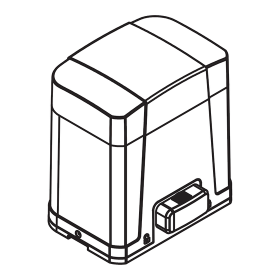
2. Installation 2.1 Standardinstallation (Signalleuchte optional) 1. Schiebetorantrieb 2. Handsender 3. Lichtschranke 4. Signalleuchte 2.2 Beschreibung der Bauteile a. Antriebsritzel e. manuelle Entriegelung b. Endschalter mechanisch f. Steuerung c. 24 V DC Motor g. Geräte-Anschlussklemme d. Back-up batterie (Nicht in EU) -
Seite 8: Abmessungen
2.3 Abmessungen 2.4 Installation des Schiebetorantriebs und der Zahnstangen... -
Seite 9: Vor Installation Prüfen
2.5 Vor Installation prüfen NEIN 2.6 Manuelle Notentriegelung Im Falle eine Stromausfalls oder Defekts nutzen Sie bitte die Notentriegelung um das Tor manuell öffnen zu können. Beachten Sie hierbei folgende Schritte: Schritt 1: Schieben Sie den Deckel der Notentriegelung nach Rechts. Schritt 2: Führen Sie den Schlüssel ein und drehen Sie diesen gegen den Uhrzeigersinn um das Schloss zu entriegeln. -
Seite 10: Funktionen Und Einstellungen
3. Funktionen und Einstellungen 3.1. Anschlussmöglichkeiten Zeigt die LED den Normalbetrieb "OP", dann kann der Torantrieb entweder mit dem Handsender bedient werden oder über die Tasten auf der Steuerung. "UP" = Bewegung in Uhrzeigersinn, "SET" = Stopp, und "DOWN" = Bewegung gegen den Uhrzeigersinn. -
Seite 11: Handsender Einlernen Oder Löschen
3.2 Handsender einlernen oder löschen (1) Handsender einlernen: Drücken Sie “RF Learn” für 2 Sekunden, das LED Display zeigt “CS”. Drücken Sie nun die linke Handsendertaste (A) - das LED Display blinkt 3-mal und nach 5 Sekunden geht aus. Der Handsender ist nun eingelernt. (2) Handsender löschen: Drücken Sie "RF Learn"... - Seite 12 LED Display Function LED Display Function “-L”: System ist nicht eingelernt “LE”: Das System ist im Lernmodus “OP”: Das System ist in Normalbetrieb. Um in das “LP”: System ist in der Lernfahrt. Öffnet Menü zu gelangen, drücken Sie "SET" für 3 Sek. und schließt automatisch.
-
Seite 13: Menü Einstellungen
3.4 Menü Einstellungen Step 1: Drücken Sie "SET" für 3 Sekunden um in das Menü zu gelangen. Step 2: Wählen Sie das gewünschte Menü (siehe Tabelle unten) und bestätigen Sie erneut mit "SET". Die zweite Zahl zeigt die Einstellung im Menü. Wählen Sie erneut mit "UP" und "DOWN" zwischen den Einstellungen und bestätigen Sie diese anschließend mit "SET". - Seite 14 LED Display Definition Function Value Description 0.1A 1.1A 2.1A 3.1A 4.1A 5.1A Einstellung der Kraftabschaltung. 0.2A 1.2A 2.2A 3.2A 4.2A 5.2A (Sicherheitsrücklauf) 0.3A 1.3A 2.3A 3.3A 4.3A 5.3A 0.4A 1.4A 2.4A 3.4A 4.4A 5.4A 0.5A 1.5A 2.5A 3.5A 4.5A 5.5A 0.6A 1.6A 2.6A...
-
Seite 15: Testen Und Überprüfen
● F3 Einstellungen Lichtschranken: Logic F3-1 PH2 Terminal PH1 Terminal Lichtschranke 1 Tor-Status Lichtschranke 2 geschlossen öffnen nicht erlaubt öffnen nicht erlaubt geöffnet kein Effekt Neustart automatischer Zulauf gestoppter Torlauf öffnen nicht erlaubt Neustart automatischer Zulauf während schließen öffnet Tor kein Effekt während öffnen kein Effekt... -
Seite 16: Technische Daten
4. Technische Daten 4.1 Technische Daten Jet 500 / Jet 800 Motor Jet 500 Jet 800 Getriebeart Schneckengetriebe Schneckengetriebe Spitzenkraft 5500N 7000N Zug- Druckkraft 5000N 6500 N Motordrehzahl 3800RPM 3800 RPM Leistung 144W 168W Steuerspannung 24 V DC 24 V DC... -
Seite 17: Installation Und Verwendung Zubehör
5. Installation und Verwendung Zubehör 5.1. Installation Lichtschranke SPC Die Lichtschranke SPC dient als zusätzliche Sicherheitseinrichtung für Torantriebe. Sie besteht aus einem Sender und einem Empfänger und reagiert bei Unterbrechung des Lichtstrahls. SPECIFICATION: Einweg-Lichtschranke Reichweite bis 25 Meter Spannungsversorgung AC/DC 12~24V Reaktionszeit 100MS Strahlart...