Märklin V 200 BR 220 Gebrauchsanleitung
Inhaltsverzeichnis
Verfügbare Sprachen
Verfügbare Sprachen
Quicklinks
220 022-8
Einfüllstutzen
Heizöl
79 t
BD Hamburg
11,
Gew ok
S
97 t
BW Hamburg-Altona
Kssbr. m. Z.
Br
Gew
P
74 t
AW Nürnberg
letzte Br Unt. 27. 8.57
G
58 t
Unt 27.8.56
Löschanlage
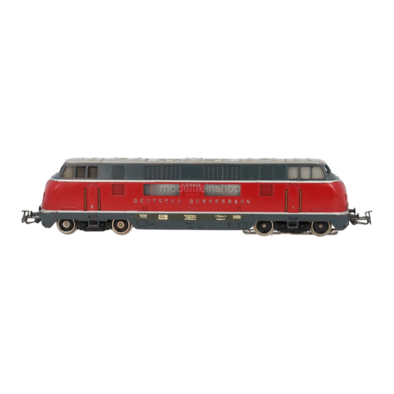
Modell der Baureihe V 200 (BR 220)
Einfüllstutzen
50
m
Kraftstoff
Einfüllstutzen
Kühlwasser
Feuerlöschschlauch
und Anschlußstutzen
Inhaltsverzeichnis

Verwandte Anleitungen für Märklin V 200 BR 220


Inhaltszusammenfassung für Märklin V 200 BR 220
- Seite 1 220 022-8 Einfüllstutzen Einfüllstutzen Heizöl 79 t BD Hamburg Kraftstoff Gew ok 97 t BW Hamburg-Altona Kssbr. m. Z. 74 t AW Nürnberg letzte Br Unt. 27. 8.57 58 t Einfüllstutzen Unt 27.8.56 Kühlwasser Löschanlage Feuerlöschschlauch und Anschlußstutzen Modell der Baureihe V 200 (BR 220)
- Seite 2 Exploitation Vorbild Seite 4 Prototype Page 4 dans le réel Page 4 Grootbedrijf Blz. 4 Betrieb Seite 7 Operation Page 15 Fonctionnement Page 23 Exploitatie Blz. 31 Betrieb auf Operation on Exploitation Bedrijf op der Anlage Seite 39 a layout Page 39 sur réseau Page 39...
- Seite 3 Vorbild Prototype Exploitation dans le réel Grootbedrijf...
-
Seite 4: Informationen Zum Vorbild
Vorbild Prototype Informationen zum Vorbild Information about the prototype Schon kurze Zeit nach der Gründung der Deutschen Bundesbahn wurden A short time after the founding of the German Federal Railroad the path was die Weichen für die zukünftige Entwicklung gestellt. Stand früher die chosen for future development. -
Seite 5: Informatie Over Het Voorbeeld
Exploitation dans le réel Grootbedrijf Information sur le modèle réel Informatie over het voorbeeld Après la fondation des Chemins de fer de la Deutsche Bundesbahn, il ne fallut Korte tijd na het oprichten van de Deutschen Bundesbahn pas attendre très longtemps pour que les grandes lignes du développement (Duitse spoorwegen) werd een nieuwe weg ingeslagen voor de toekomstige futur soient tracées. -
Seite 6: Betrieb
Betrieb 2.1 Funktion Diese Lok mit eingebauter • Automatische Erkennung zwischen • Fahrtrichtungsabhängige • Eingebaute Führerstandsbeleuch- Digital-Elektronik bietet: konventionellem Betrieb und Beleuchtung im Betrieb mit der tung in beiden Führerständen. Mehrzug-Betrieb. Die Auswahl Control Unit, der Mobile Station • Wahlweiser konventioneller zwischen Wechselspannung und oder der Central Station ein-/ aus- •... -
Seite 7: Einstellen Der Betriebsart
Betrieb 2.2 Einstellen der Betriebsart 2.3 Einstellen der Digital- 2.4 Einstellen der Fahr- P1: Anfahr- / Bremsverzögerung adresse parameter (gemeinsam) Linksanschlag: minimale Verzögerung. 1. Gehäuse abnehmen (=> Seite 41). 1. Gehäuse abnehmen (=> Seite 41). 1. Gehäuse abnehmen (=> Seite 41). Rechtsanschlag: maximale Verzögerung. - Seite 8 Betrieb Digital Digital Digital – 2 3 – 5 – 7 – – – 2 3 – 5 – – 8 – – 2 3 – 5 – – – – – – 3 – 5 – 7 – – –...
-
Seite 9: Betrieb Mit Den Einzelnen
Betrieb 2.5 Betrieb mit den einzelnen 2.5.1 Betrieb mit der Mobile Station/ 2.5.2 Betrieb mit Digital Fahrbetrieb mit der Versorgungs-Systemen Central Station Control Unit 6021: Hinweis: Dieses Modell ist zum wahlweisen Zur Aufnahme dieser Lokomotive in Zum Fahrbetrieb können alle Märklin Lokadresse eingeben. -
Seite 10: Fahren Der Lok Mit Delta
Betrieb Hinweis: Durch ein weiteres Betätigen der Durch Drehen des Fahrreglers aus 2.5.4 Fahren mit Wechselspannung Die Fahrtrichtung wird bei der Taste „f2“ wird das Geräusch wieder der Mittelstellung heraus nach rechts Control Unit 6021 über zwei Pfeile ausgeschaltet. fährt die Lok vorwärts. Durch Drehen In der Betriebsart „Wechselspannung“... -
Seite 11: Fahren Mit Gleichspannung
Betrieb Von den Funktionen f1 bis f4 ist im Hinweis: H0-Gleichspannungs-Fahr- 2.6 Die eingebaute Diesel- Die Abstimmung der Geräuschelek- Betrieb die Funktion f1 immer einge- geräte geben eine maximale Span- geräuschelektronik tronik muss beim Fahren der Lok schaltet. Die restlichen Funktionen nung von ±12 Volt ab. - Seite 12 Betrieb Hinweis: Überprüfen Sie die Stellung Zur kompletten Justierung der • Am Poti P1 kann die Lautstärke • Bei korrekt abgestimmter Geräu- des Jumpers (Brückenstecker) auf der Geräuschelektronik werden verändert werden. Bedenken schelektronik muss nach dem Geräuschplatine. Der Jumper muss folgende Schritte durchgeführt.
- Seite 13 Betrieb Bitte beachten Sie folgende Punkte • Der Leistungsbedarf der Geräusch- beim Betrieb der Geräuschelek- elektronik liegt bei ca. 12 VA. tronik. Dadurch verringert sich die maxi- male Anzahl an Lokomotiven pro • Die Geräuschelektronik benötigt Versorgungsbereich. eine Mindest-Versorgungsspan- • Bei dauerndem Betrieb der Lok nung von 12 Volt.
-
Seite 38: Betrieb Auf Der Anlage Operation On A Layout
Betrieb auf der Anlage Operation on a layout 3.1 Anschluss der Gleisanlage mindestens 300 mm langen Gleis- 3.1 Connections between gradually up to maximum grade for the stücken darf maximal 1 bis 1,5 Prozent the track layout and route. The maximum allowable diffe- betragen. -
Seite 40: Wartung
Wartung Maintenance Entretien Onderhoud 4.1 Gehäuse abnehmen 4.1 Enlever le carter Um die hervorstehenden Teile auf Afin de protéger les pièces en saillie dem Dach der Lok vor Beschädigung sur le toit de la locomotive contre zu schützen, wird die Lok mit der les détério rations, la locomotive est Dachseite nach unten in das Oberteil disposée toit en bas dans la partie... -
Seite 41: Schmierung Nach 40 Betriebsstunden
Wartung Maintenance Entretien Onderhoud 4.2 Schmierung nach 40 Betriebsstunden Nur die Kardangelenke an den eingezeichneten Stellen nach ca. 40 Betriebs- stunden ölen. Nur Märklin Schmieröl (Nr. 7149) verwenden! Die anderen Getriebeteile sind wartungsfrei. 4.2 Lubrication after 40 hours of operation Only the universal joint is to be oiled at the places indicated after approxi- mately 40 hours of operation. -
Seite 42: Haftreifen Wechseln
Wartung Maintenance Entretien Onderhoud 4.3 Haftreifen wechseln Changing non skid-tires Remplacement des bandages adhérents Nieuwe antislipbanden omleggen 471 000... - Seite 43 Wartung Maintenance Entretien Onderhoud 4.4 Schleifer wechseln Die Schleifer sind zusätzlich angelötet. 544 840 4.4 Changing pick-up shoes The pickup shoes are also soldered in place on the locomotive. 4.4 Remplacement des frotteurs Les frotteurs sont joints en plus par brasage. 4.4 Nieuwe sleepcontacten aanbrengen De sleper is apart gesoldeerd.
-
Seite 44: Kupplung Austauschen
Wartung Maintenance Entretien Onderhoud 4.5 Kupplung austauschen 4.5 Changing couplers 4.5 Remplacer l’attelage 4.5 Koppeling vervangen Beim Aufstellen der Lokomotive If the locomotive is to be on static Les attelages automatiques peuvent Wanneer de locomotief als vitrine- als Vitrinenmodell können die auto- display, then automatic couplers can être remplacés par les attelages à... -
Seite 45: Pflegehinweis
Wartung Maintenance Entretien Onderhoud 4.6 Pflegehinweis 4.6 Remarque sur l’entretien Diese Lok kann auch im Außenbereich eingesetzt werden. Ein Betrieb bei Cette locomotive peut également être mise en service à l’air libre. Une utilisa- schlechten Witterungsbedingungen (Schnee oder Regen) wird nicht empfohlen. tion par mauvais temps (neige ou pluie) n’est pas recommandée. - Seite 46 This device complies with Part 15 of the FCC Rules. Operation is subject to the following two conditions: (1) This device may not cause harmful interference, and (2) this device must accept any interference received, including interference that may cause undesired operation. Gebr.