Gemü 675 Original Einbau- Und Montageanleitung
Metall, dn 15 - 150
Vorschau ausblenden
Andere Handbücher für 675:
- Original einbau- und montageanleitung (32 Seiten) ,
- Betriebsanleitung (27 Seiten) ,
- Original einbau- und montageanleitung (36 Seiten)

Verwandte Anleitungen für Gemü 675


Inhaltszusammenfassung für Gemü 675
- Seite 1 Membranventil Metall, DN 15 - 150 Diaphragm Valve Metal, DN 15 - 150 ORIGINAL EINBAU- UND MONTAGEANLEITUNG INSTALLATION, OPERATING AND MAINTENANCE INSTRUCTIONS...
-
Seite 2: Inhaltsverzeichnis
Inhaltsverzeichnis Allgemeine Hinweise Voraussetzungen für die einwandfreie Allgemeine Hinweise Funktion des GEMÜ-Ventils: Allgemeine Sicherheitshinweise 2 Sachgerechter Transport und Lagerung Hinweise für Service- Installation und Inbetriebnahme durch und Bedienpersonal eingewiesenes Fachpersonal Warnhinweise Bedienung gemäß dieser Einbau- und Verwendete Symbole Montageanleitung Begriff sbestimmungen Ordnungsgemäße Instandhaltung Vorgesehener Einsatzbereich Technische Daten... -
Seite 3: Hinweise Für Service
Hinweise für Service- Warnhinweise und Bedienpersonal Warnhinweise sind, soweit möglich, nach folgendem Schema gegliedert: Die Einbau- und Montageanleitung enthält grundlegende Sicherheitshinweise, die bei SIGNALWORT Inbetriebnahme, Betrieb und Wartung zu beachten sind. Nichtbeachtung kann zur Art und Quelle der Gefahr Folge haben: ®... -
Seite 4: Verwendete Symbole
Verwendete Symbole Vorgesehener Einsatzbereich Das GEMÜ-Membranventil 675 ist für Gefahr durch heiße Oberfl ächen! den Einsatz in Rohrleitungen konzipiert. Es steuert ein durchfließendes Medium durch Handbetätigung. Gefahr durch ätzende Stoff e! Das Ventil darf nur gemäß den technischen Daten eingesetzt werden Hand: Beschreibt allgemeine (siehe Kapitel 5 "Technische Daten"). -
Seite 5: Technische Daten
Technische Daten Betriebsmedium Umgebungsbedingungen Aggressive, neutrale, gasförmige und flüssige Medien, die Umgebungstemperatur 0 bis 60 °C die physikalischen und chemischen Eigenschaften des jeweiligen Gehäuse- und Membranwerkstoffes nicht negativ beeinflussen. Max. zul. Temperatur des Betriebsmediums 150 °C (je nach Medium, Membran- und Ventilkörperwerkstoff) Betriebsdruck [bar] Kv-Wert Membrangröße... -
Seite 6: Bestelldaten
Bestelldaten Gehäuseform Code Ventilkörperwerkstoff Code Durchgang EN-GJL-250 (GG 25) EN-GJS-400-18-LT (GGG 40.3) PFA-Auskleidung EN-GJS-400-18-LT (GGG 40.3) PP-Auskleidung Anschlussart Code EN-GJS-500-7 (GGG 50) PFA-Auskleidung Gewindeanschluss EN-GJS-400-18-LT (GGG 40.3) Hartgummi-Auskleidung 83 Gewindemuffe DIN ISO 228 EN-GJS-500-7 (GGG 50) PP-Auskleidung Flansch Flansch EN 1092 / PN16 / Form B, Baulänge EN 558, Reihe 1, ISO 5752, basic series 1 Membranwerkstoff... -
Seite 7: Herstellerangaben
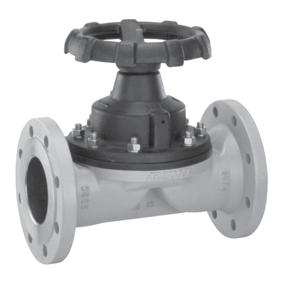
Herstellerangaben Funktionsbeschreibung Das handgesteuerte 2/2-Wege- Membranventil GEMÜ 675 in Metall- Transport ausführung besitzt ein nichtsteigendes Handrad und eine serienmäßig integrierte Membranventil nur auf geeignetem Lademittel transportieren, nicht stürzen, Sichtanzeige. Ventilkörper und Membrane sind gemäß Datenblatt in verschiedenen vorsichtig handhaben. Ausführungen erhältlich. -
Seite 8: Montage Und Bedienung
10 Montage und Bedienung Installationsort: Vor Einbau: VORSICHT Eignung Ventilkörper- und Ventil äußerlich nicht stark Membranwerkstoff entsprechend beanspruchen. Betriebsmedium prüfen. Installationsort so wählen, dass Ventil Siehe Kapitel 5 "Technische Daten". nicht als Steighilfe genutzt werden kann. Rohrleitung so legen, dass Schub- und Biegungskräfte, sowie Vibrationen 10.1 Montage des und Spannungen vom Ventilkörper... -
Seite 9: Bedienung
10.2 Bedienung Montage bei Gewindeanschluss: Gewindeanschluss entsprechend der Optische Stellungsanzeige gültigen Normen in Rohr einschrauben. Membranventilkörper an Rohrleitung anschrauben, geeignetes Gewindedichtmittel verwenden. Das Gewindedichtmittel ist nicht im Lieferumfang enthalten. Montage bei Flanschanschluss: Ventil off en Ventil geschlossen 1. Auf saubere und unbeschädigte Dichtflächen der Anschlussflansche VORSICHT achten. -
Seite 10: Montage / Demontage Von Ersatzteilen
11 Montage / Demontage 11.3 Montage Membrane von Ersatzteilen 11.3.1 Allgemeines Wichtig: Für Ventil passende Membrane einbauen (geeignet für Medium, Mediumkonzentration, Temperatur und Druck). Die Absperrmembrane ist ein Verschleißteil. Vor Inbetriebnahme und über gesamte Einsatzdauer des Membranventils technischen Zustand und Funktion überprüfen. -
Seite 11: Montage Der Konkav-Membrane
Das Druckstück ist fest verschraubt. 1. Antrieb A in Geschlossen-Position bringen. Druckstück und Antriebsfl ansch von unten 2. Neue Membrane von Hand fest in gesehen: Druckstück einschrauben. 3. Kontrollieren ob Membrandom in Druckstückaussparung liegt. 4. Bei Schwergängigkeit Gewinde prüfen, beschädigte Teile austauschen (nur Originalteile von GEMÜ... -
Seite 12: Montage Antrieb Auf Ventilkörper
5. Membranschild von Hand fest 7. Komplett montiertes Ventil auf Dichtheit in Druckstück einschrauben. prüfen. Der Membrandom muss in der Wichtig: Druckstückaussparung liegen. Wartung und Service: Verbin- Druckstückaussparung Membranen setzen sich im dungs- stück Laufe der Zeit. Nach Montage / Demontage des Ventils Druck- Schrauben 18 und Muttern 20... -
Seite 13: Inspektion Und Wartung
13 Inspektion und Wartung 14 Demontage Demontage erfolgt unter den gleichen WARNUNG Vorsichtsmaßnahmen wie die Montage. Unter Druck stehende Armaturen! Membranventil demontieren ® Gefahr von schwersten Verletzungen (siehe Kapitel 11.1 "Demontage Ventil oder Tod! (Antrieb vom Körper lösen)"). Nur an druckloser Anlage arbeiten. VORSICHT 15 Entsorgung Heiße Anlagenteile! -
Seite 14: Hinweise
17 Hinweise Hinweis zur Mitarbeiterschulung: Hinweis zur Richtlinie Zur Mitarbeiterschulung nehmen 2014/34/EU (ATEX Richtlinie): Sie bitte über die Adresse auf der Ein Beiblatt zur Richtlinie letzten Seite Kontakt auf. 2014/34/EU liegt dem Produkt bei, sofern es gemäß ATEX bestellt Im Zweifelsfall oder bei Missverständnissen wurde. -
Seite 15: Schnittbild Und Ersatzteile
19 Schnittbild und Ersatzteile Leckagebohrung Pos. Benennung Bestellbezeichnung K600… (DN 15-50) Ventilkörper K620… (ab DN 65) 600…M… (DN 15-50) Membrane 620…M… (ab DN 65) Schraube Scheibe 675...S30... Mutter Antrieb 9675... 15 / 32... -
Seite 16: Eg-Konformitätserklärung
GEMÜ Gebr. Müller Apparatebau GmbH & Co. KG Fritz-Müller-Straße 6-8 D-74653 Ingelfi ngen erklären, dass unten aufgeführte Armaturen die Sicherheitsanforderungen der Druckgeräte- richtlinie 97/23/EG erfüllen. Benennung der Armaturen - Typenbezeichnung Membranventil GEMÜ 675 Benannte Stelle: TÜV Rheinland Berlin Brandenburg Nummer: 0035 Zertifi kat-Nr.: 01 202 926/Q-02 0036 Konformitätsbewertungsverfahren:... - Seite 32 GEMÜ Gebr. Müller Apparatebau GmbH & Co. KG · Fritz-Müller-Str. 6-8 · D-74653 Ingelfi ngen-Criesbach Telefon +49(0)7940/123-0 · Telefax +49(0)7940/123-192 · info@gemue.de · www.gemu-group.com...