FLEISCHMANN ICE 2 Betriebsanleitung
Quicklinks
21-4490-0101_109:21-4490-0101_109
19.01.2009
14:03 Uhr
Seite 1
Kuppeln zweier ICE 2
Wie beim großen Vorbild können auch beim FLEISCHMANN-ICE 2 zwei Halbzüge miteinander gekuppelt werden. Drei
Kupplungen, die in einen Normschacht nach NEM 362 gesteckt werden, stehen zur Verfügung:
Lange Kuppelstange (38 6004, nicht im Liefer umfang ent-
halten): Mit ihr werden zwei ICE 2-Halb züge fest miteinander
verbunden. Durch den et was weiteren Fahr zeug abstand kön-
nen alle Gleisfi guren der FLEISCHMANN-Gleise befahren wer-
den.
Kurze Kuppelstange (38 6010): Mit ihr werden zwei ICE 2-
Halbzüge fest miteinander verbunden. Diese Kuppel stange bie-
tet einen sehr kurzen Fahrzeug abstand. Alle Gleisradien sowie
alle Weichenzu sam men stellungen kön nen mit ihr befahren wer-
den.
PROFI-Kupplung (6515): Sind die Triebköpfe und Steuerwagen
zweier Halb züge mit PROFI-Kupplungen ausgerüstet, können
die Züge z.B. im Bahnhof leicht zu einer Vollgarnitur gekuppelt
und ebenso leicht wieder entkuppelt werden. Alle Gleis radien
sowie alle Weichenzusammen stellungen kön nen mit ihr befah-
ren werden.
Bugkappe von zwei Fahrzeugen (Motor- und / oder Steuer wagen) abnehmen. Abdeckplatten einsetzen.
38 6004
38 6010
6515
Kuppeln mit der Kuppelstange: Kuppelstange in den Kupplungsschacht einführen, bis sie einrastet. Das mit der
Kuppelstange ausgerüstete Fahrzeug aufs Gleis stel len und mit einem zweiten Triebkopf bzw. Steuer wa gen ohne
Kuppelstange verbinden. Die beiden ICE 2 - Züge sind fest miteinander verbunden.
Kuppeln mit der PROFI-Kupplung: PROFI-Kupplung in den Kupplungsschacht einführen, bis sie einrastet. Einen
zweiten Triebkopf oder Steuerwagen ebenfalls auf diese Weise mit der PROFI-Kupplung ausrüsten. Durch einfaches
Zusammenschieben sind die Fahr zeuge gekuppelt. Zum Entkuppeln empfehlen wir den Ein satz eines Ent kupp-
lungsgleises (MODELL-Gleis 6012, 6014, PROFI-Gleis 6111, 6114).
Kuppeln von Triebkopf / Steuerwagen und Mittelwagen mit der Kuppelstange 38 6006:
Kuppelstange 38 6006 in die obere Öffnung der Kupplungs-
Das mit der Kuppelstange 38 6006 ausgerüstete Fahrzeug wird
auf nahme mit „Stern" stecken und fest einrasten lassen.
mit einem Fahrzeug ohne Kuppelstange verbunden. Dazu Kup-
Verdickung nach unten! Der Stern befindet sich am Steuer-
pelstange 38 6006 in die obere Öffnung der Kupplungsauf-
wagen und an den Mittelwagen mit glatten Dachenden (ohne
nahme ohne „Stern" einklippsen. Die gefederten Übergänge
Deckel).
berühren sich nach dem Kuppeln.
Trennen von Triebkopf / Steuerwagen und Mittelwagen mit der Kuppelstange 38 6006:
Fahrzeuge in Pfeilrichtung auseinanderziehen. Dabei bleibt die
Kuppelstange mit der „Stern"-Seite fest verbunden. Auf diese
Weise wird erreicht, dass die Mittelwagen immer vorbildlich
gereiht zueinander stehen (glatte Dachenden zu Dachenden mit
Deckel)
Wenn auch beim Vorbild die einzelnen ICE-Fahrzeuge praktisch nicht entkuppelt werden, bietet dennoch der FLEISCHMANN-ICE
die Möglichkeit, mit der PROFI-Kupplung zu kuppeln, zu entkuppeln und sogar vorzuentkuppeln.
Kuppeln von Triebkopf / Steuerwagen und Mittelwagen mit der PROFI-Kupplung 6515:
Auf der „Stern"-Seite die Kuppelstange 38 6006 anheben und gleichzeitig abziehen. PROFI-Kupplung in die untere Öffnung der
Kupplungsaufnahme einstecken. Gegebenenfalls beim Befahren enger Radien in Verbindung mit der PROFI-Kupplung die Schürzen
am Wagenboden entfernen. Dazu mit einem Bastelmesser entlang der gestrichelten Linie eine Einkerbung herstellen und dann die
Schürzen mit einem Seitenschneider entfernen.
Triebkopf / Steuerwagen
Mittelwagen
Gegebenenfalls beim Befahren enger Radien in Verbindung mit der PROFI-Kupplung die Schürzen am Wagenboden an den
vorgesehenen Bruchkanten entfernen.
Fig. 2
Fig. 3
Stromzuführung über das Gleis: Schlitz des Schalters
Stromzuführung über die Oberleitung: Schlitz des
quer zur Fahrtrichtung stellen (Fig. 2).
Schalters längs zur Fahrtrichtung stellen (Fig. 3).
--- Nicht bei 6382 ! ---
Die Spitzenbeleuchtung an Triebkopf und Steuerwagen wechselt automatisch mit der Fahrtrichtung von vorwärts weiß
auf rückwärts rot. Der Steuerwagen ist mit einem mechanischen Beleuchtungsumschalter ausgerüstet.
Lampenwechsel am Triebkopf:
Fig. 5
a
Bugkappe abnehmen und anschließend
den Frontspoiler herausnehmen.
Schraube a lösen und Schaltplatine
herausheben. Mit Pinzette Lampe
herausnehmen (Fig. 4 und 5).
Ersatzlampe weiß:
6535 (hintere Bohrung)
Ersatzlampe rot:
9531 (vordere Bohrung)
Fig. 4
Lampenwechsel am Steuerwagen:
Fig. 7
Bugkappe abnehmen und anschließend
b
den Frontspoiler mitsamt dem
Wagenkasten-Unterteil abnehmen.
Halte nase b nach hinten drücken und
Schaltplatine nach vorne herausheben.
Mit Pinzette Lampe herausnehmen
(Fig. 6 und 7).
Ersatzlampe weiß:
6535 (hintere Bohrung)
Ersatzlampe rot:
9531 (vordere Bohrung)
Fig. 6
Vor der Befestigung der Schaltplatine auf sicheres An lie gen der Kontaktfedern achten.
In den Steuerwagen kann die Innenbeleuchtung 6464 eingebaut werden.
Fig. 8
Kohlenwechsel: Der Motor ist im hinteren Drehgestell des Trieb-
kopfes eingebaut. Drehgestell am Mittelsteg zusammendrücken
und aus Führung nach unten herausziehen. Achtung: Auf
freistehende Teile achten! Ersatzkohlen einsetzen (Fig. 8).
Ersatzkohlen: 6519
Fig. 9
Ölen: Geölt werden Motor und Getriebe nur an den gekennzeichneten Lagerstellen (Fig. 8, 9 und 10).
Nur FLEISCHMANN-ÖL 6599 verwenden. Nur ein kleiner Tropfen pro Schmierstelle (
), sonst
Überölung. Zur Dosierung die in der Verschlusskappe der Ölflasche angebrachte Nadel verwenden.
Ein Ölen der Radlager beim Steuerwagen ist nicht notwendig.
Triebkopf
Nicht bei 6382 !
9426 / 9427
Fig. 10
An der schraffierten Stelle kann der Schaltmagnet 9426 / 9427 eingebaut werden.
Dieser Stern bezeichnet nach Norm NEM 621 die masseführende „gemeinsame Seite" des Triebwagens (Fig. 10).
Ersatzhaftreifen: 54 4007
c
a
Fig. 11
Ein Öffnen des Triebwagens ist nur zum Einbau eines digitalen Empfängerbausteins erforderlich. Die Schraube c und
a lösen (siehe auch Fig. 4) und das Gehäuse nach oben abheben (Fig. 11).
ACHTUNG: Vor Decodereinbau müssen die Lötstellen der Steckplatine und der Metallring des Motors (z.B. durch
Klebepad) elektrisch voneinander isoliert werden. Einbau eines digitalen Empfängerbausteins: Auf den schraffierten
Platz kann ein DECODER (DCC: 6876, TWIN: 6847) mit 6-poligem Stecker (NEM 651) geklebt werden (Fig.11). Beim
Einbau bitte die Betriebsanleitung des DECODERs beachten.
ICE 2-Power car and trailer car
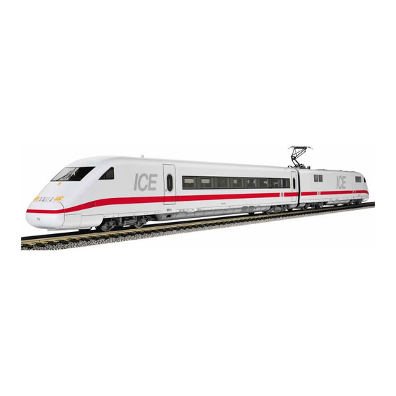
As a further development of the ICE, the ICE 2 has been in service on the DB since 1998. One train consists of one power car, 6
intermediate coaches and one cab-trailer car (half-train). As required, two of these shorter half-trains can be coupled together to make up
one complete set (Fig. 1).
Coupling two ICE 2 together
Just like the larger prototype, two FLEISCHMANN half-trains can also be coupled together. Three types of couplings, which will fit into the
standard coupling socket NEM 362, are availiable:
Long coupling bar (38 6004, not contained in pack): Using this bar, two ICE 2 half-trains can be permanently joined together. Because
of the rather larger distance between vehicles, all track configurations of FLEISCHMANN track can be negotiated.
Short coupling bar (38 6010): Using this bar, two ICE 2 half-trains can be permanently joined together. This coupling bar gives a very close
distance between vehicles. All track radii and point configurations can be negotiated.
PROFI-Coupling (6515): If the power and trailer cars of two half-trains are fitted with PROFI-couplings, then two trains, in the station for
example, can be easily coupled up together to make up a full set and just as easily uncoupled again. All track radii and point configurations
can be negotiated.
Remove the bow doors from two vehicles (power- and/or trailer car). Insert cover plate.
Coupling up using the coupling bar: Insert the coupling bar into the coupling socket until it clicks into position. Put the vehicle fitted with
the coupling bar onto the track, and join up the second power car without coupling bar or similarly the trailer car. The two ICE 2 trains are
now permanently joined together.
Coupling up using the PROFI-coupling: Insert the PROFI-coupling into the coupling socket until it clicks into position. In the same
manner fit a PROFI-coupling to a second power or trailer car. By simply pushing the two vehicles together they will then couple up. To
uncouple, we recommend the use of the uncoupler track (Model-Track 6012, 6014, PROFI-Tracks 6111, 6114).
Coupling up driving coaches and centre coaches with the coupling bar 38 6006: Insert the coupling bar 38 6006 into the upper
opening of the coupling socket marked with the star, clipping it firmly in position. Nose downwards!
The star can be located on the trailer car and on the centre coaches with smoothed roof ends (without cover).
The vehicle now fitted with the coupling bar 38 6006 can be coupled with one without the coupling bar. To do so, clip the coupling bar 38
6006 into the upper opening of the coupling socket without the star. After coupling, the sprung connections will meet each other.
Separating the driving coach and centre coaches with the coupling bar 38 6006: Pull the vehicles apart in the direction of the arrow.
The coupling bar will then remain fixed in the star side. In this way, the centre coaches will always be prototypically correctly in sequence
with each other (smooth roof end to roof end with cover).
Even though in the prototype, the individual ICE vehicles are practically never uncoupled, the FLEISCHMANN ICE however may be
coupled together with the PROFI-coupling making it possible to couple, uncouple and pro-uncouple as well.
Coupling the driving coach and centre coaches using the PROFI-coupling 6515: Lift up and simultaneaously pull out the coupling bar
38 6006 from the end marked +. Insert the PROFI-coupling into the lower opening of the coupling socket.
Driving coach: It may be necessary, when running round tighter radii whilst using the PROFI-coupling, to remove the skirts on the coach
chassis. To do so, use a small hobby knife to score along the printed line and snip off the skirts using side cutters.
Centre coach: If running around very tight radius curves using the PROFI-coupling, then the skirting of the coach body must be removed
at the previously marked points.
Current pick-up from track: Set the slit of the switch across the direction of travel (Fig. 2). Current pick-up from cate nary: Set the slit
of the switch to the direction of travel (Fig. 3).
The headlights of the power car and trailer car change automatically, co-ordinated with the direction of travel, forwards white and
backwards red. The trailer car has a mechanical light switch.
Changing the bulbs on the power car: Remove the bow doors and then take out the front spoiler. Undo screw a, and lift out the printed
circuit board. Using tweezers, take out the bulbs (Fig. 4, 5).
Changing the bulbs on the trailer car: Remove the bow doors and then take out the front spoiler together with the lower part of the coach
body. Push back the retaining clip b, and pushing forwards, lift out the printed circuit board. Using tweezers, take out the bulbs (Fig. 6, 7).
Spare red bulb: 9531 (rear socket) • Spare white bulb: 6535 (forward socket)
Before fixing the circuit board back in place, ensure that the contact springs are correctly positioned. The interior lighting unit 6464 can
be installed in the trailer car.
Changing brushes: The motor is mounted on the rear bogie of the driving coach. Press the centre of the bogie sides together and genttly
pull downwards out of the body. Insert the brushes (Fig. 8).
Spare brushes: 6519
Lubrication: The motor and gear-box need only be lightly oiled at the bearing points marked (Fig. 8, 9, 10). Only use FLEISCHMANN-oil
6599. Only put a tiny drop in each place (
), otherwise it will be overoiled. An applicator needle is located in the cap of the oil bottle for
your use. Oiling the wheel bearings of the trailer car is not necessary.
The indicated point can be used for locating the switching magnet 9426/9427 (Fig. 10).
This star indicates the "common side" of the loco conforming to the standard NEM 621 (Fig. 10).
Spare Traction Tyres: 54 4007
Opening the power car: Opening the power car is only necessary to install a digital receiver. Remove screws c and a (see also Fig. 4)
and lift the loco body upwards (Fig. 11).
ATTENTION: Before installing the decoder, the soldered areas on the plug printed circuit board and the metal ring of the motor must be
electrically isolated from each other (i.e. by using the adhesive strip).
Installing the digital decoder: A 6-pole DECODER (DCC: 6876, TWIN: 6847) (NEM 651) can be glued onto the cross-hatched surface
(Fig. 11). Please consult the instructions included with the DECODER for fitting advice.
ICE 2 Motrice et voiture pilote
Le train ICE 2, évolution du train à grande vitesse ICE, circule depuis 1998 à la DB. Une rame est composée d'une motrice, de 6 voitures
intermédiaires et d'une voiture pilote (demi-train). Au besoin, deux de ces rames peuvent être couplées pour former une rame complète.
Attelage de deux ICE 2
Comme sur l'orginal en teille réelle, le train ICE 2 de FLEISCHMANN autorise l'attelage de deux demi-trains. Trois types d'attelage
s'emboîtant dans le boîter récepteur normé NEM 362 sont disponibles:
Timon d'attelage long (38 6004, nonfourni): pour atteler de façon permanente deux demi-trains ICE 2. La distance entre voitures ainsi
obtenue permet de parcourir toutes les configurations de réseau réalisées avec les voies FLEISCHMANN.
Timon d'attelage court (38 6010): pour atteler de façon permanente deux demi-trains ICE 2. Cet attelage permet d'avoir un espace
minimum entre voitures. Attelage adapté à tous les rayons de voies et configuration d'aiguillages.
Attelage PROFI (6515): équipées d'attelages PROFI, les motrices et voitures pilotes de deux demi-trains peuvent être facilement attelées
par exemple en gare en une rame complète et facilement dételées. Attelage adapté à tous les rayons de voies et configurations
d'aiguillages.
Retirer la coiffe de nez de deux voitures (motrice et/ou voiture pilote). Poser les caches.
Pour atteler au moyen du timon: introduire le timon dans le boîter récepteur jusqu'à emboîtement. Poser le véhicule équipé du timon sur la
voie et le relier à une autre motrice ou voiture pilote non munie de timon. Les deux trains ICE 2 sont à présent attelés de façon permanente.
Pour atteler au moyen de l'attelage PROFI: intoduire l'attelage PROFI dans le boîter récepteur jusqu'à emboitement. Equiper une

Verwandte Anleitungen für FLEISCHMANN ICE 2


Inhaltszusammenfassung für FLEISCHMANN ICE 2
- Seite 1 Drehgestell am Mittelsteg zusammendrücken As a further development of the ICE, the ICE 2 has been in service on the DB since 1998. One train consists of one power car, 6 Wie beim großen Vorbild können auch beim FLEISCHMANN-ICE 2 zwei Halbzüge miteinander gekuppelt werden. Drei und aus Führung nach unten herausziehen.
- Seite 2 Dette tog mu kun anvendes med en jæavnstrømtransformator De ICE 2 is de opvolger van de ICE en wordt sinds 1998 bij de DB ingezet. Een trein bestaat uit een aandrijfwagen, 6 tussen rijtuigen en Montering af kobbelstang: Koblingsstangen skubbes ind i hakket til klik. Stil begge enheder på skinnen og skub stangen ind i modsatte corpo della carrozza.