Inhaltsverzeichnis
Werbung
Verfügbare Sprachen
Verfügbare Sprachen
Quicklinks
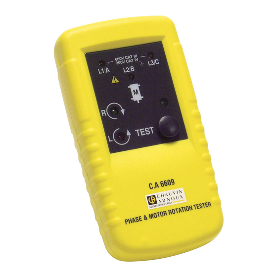
Testeur de sens moteur et rotation
de phases
Motor and Phase rotation indicator
Drehfeldrichtungsanzeiger
Tester di senso motore e rotazione
delle fasi
Comprobador de sentido de motor
y rotación de fases
F R A N Ç A I S
Notice de fonctionnement
E N G L I S H
User's manual
D E U T S C H
Bedienungsanleitung
I T A L I A N O
Manuale d'uso
ESPAÑOL
Manual de instrucciones
C.A 6609
Werbung
Inhaltsverzeichnis

Verwandte Anleitungen für Chauvin Arnoux C.A 6609


Inhaltszusammenfassung für Chauvin Arnoux C.A 6609
- Seite 1 Testeur de sens moteur et rotation C.A 6609 de phases Motor and Phase rotation indicator Drehfeldrichtungsanzeiger Tester di senso motore e rotazione delle fasi Comprobador de sentido de motor y rotación de fases F R A N Ç A I S...
- Seite 28 Deutsch Sie haben einen CA 6609 Drehfeldrichtungsanzeiger erstanden, wir danken Ihnen für Ihr Vertrauen. Für die Erlangung eines optimalen Betriebsverhaltens Ihres Gerätes: • Lesen Sie bitte diese Betriebsanleitung aufmerksam durch und, • Beachten Sie bitte die Anwendungshinweise. Bedeutung der Gerätesymbole Achtung –...
- Seite 29 Deutsch Definition der Messkategorien: KAT I: Stromkreise, die nicht direkt mit dem Stromnetz verbunden sind oder geschützt sind. Beispiel: geschützte Stromkreise. KAT II: Stromkreise an Niederspannungsanlagen. Beispiel: Stromversorgung Haushaltsgeräten oder tragbaren Elektrowerkzeugen. KAT III: Stromversorgungskreise innerhalb der Haus- oder Gebäudeinstallation Beispiel: Verteiler, Leistungsschalter,...
- Seite 30 Deutsch Dieses Gerät prüft nicht, ob Spannung vorhanden ist oder nicht (VAT). Die Leuchtanzeigen für das Vorhandensein der Phasen L1, L2, L3 dürfen also nicht als Spannungsanzeige verstanden werden! Für die Spannungsprüfung muss immer ein VAT verwendet werden. Das Gerät erfüllt die Anforderungen für Stromkreise der Messkategorie III, es besitzt einen Überlastschutz 600V Erde.
-
Seite 31: Auspacken - Einpacken
Deutsch Achtung! Bei Überschreitung von 70Vdc oder 33VRMS und 46,7V Peak Spannungen besteht Schockgefahr. empfehlen nach Arbeitsbedingungen geeignete Schutzkleidung zu tragen. Die Hände müssen beim Messen immer hinter der Schutzvorkehrung der Prüfspitzen und der Krokodilklemmen liegen. Vor dem Öffnen des Gehäuses immer alle Prüfdrähte von Quelle und Gerät abnehmen. -
Seite 32: Gerätebeschreibung
Deutsch Feststellen von Phasen (wenn Spannung gegen Nullleiter > 100V); Bestimmung der Motordrehrichtung mit oder ohne Anschluss; Bestimmung der Elektroventilaktivierung ohne Anschluss. GERÄTEBESCHREIBUNG 1. Buchse für Prüfdraht 2. Anzeigeleuchte L1, L2 und L3 3. Anzeige Drehrichtung Uhrzeigersinn 4. Anzeige Drehrichtung gegen den Uhrzeigersinn 5. -
Seite 33: Einsatz Des Geräts
Deutsch EINSATZ DES GERÄTS BESTIMMUNG DER DREHFELDRICHTUNG An einem Dreiphasennetz: Schließen Sie die 3 Drähte gemäß der Kennzeichnung an das Gerät an. Schließen Sie nun die 3 Krokodilklemmen an die 3 Phasen des zu überprüfenden Netzes an. Drücken Sie auf ON. Die grüne Anzeigeleuchte zeigt den Gerätebetrieb an. - Seite 34 Deutsch Anzeige richtig falsch fehlt ACHTUNG! Wenn die Spannung zu schwach ist, leuchten die Leuchtanzeigen der Phasen L1, L2, L3 eventuell nicht (siehe Abs. 3).
- Seite 35 Deutsch ANZEIGE DER DREHFELDRICHTUNG BZW. DREHRICHTUNG OHNE ANSCHLUSS Es darf keine Messleitung an das Gerät angeschlossen sein. Halten Sie das Gerät in höchstens 2,5 cm Abstand über den Motor, und zwar parallel zur Welle. Beachten Sie das Positionssymbol an der Vorderseite. Drücken Sie auf ON.
- Seite 36 Deutsch Drehzahl des Drehfelds Mindestdurchmesser des Anzahl (1/min) nach Frequenz Polwinkel Motorgehäuses Polpaare (Hz) 16 2/3 1000 3000 3600 1500 1800 10.7 1000 1200 16.0 21.4 26.7 32.1 42.8 53.5 64.2 3.75 85.6 BESTIMMUNG DER ANSCHLUSSRICHTUNG DER LEITERDRÄHTE AN EINEM MOTOR Schließen Sie die 3 Drähte gemäß...
-
Seite 37: Technische Spezifikationen
Deutsch ANZEIGE DER ELEKTROVENTILAKTIVIERUNG OHNE ANSCHLUSS Es darf keine Messleitung an das Gerät angeschlossen sein. Halten Sie das Gerät so nahe wie möglich an das Elektroventil. Drücken Sie auf ON. Die grüne Anzeigeleuchte zeigt den Gerätebetrieb an. Die Anzeigeleuchte „Uhrzeigersinn / gegen Uhrzeigersinn“ zeigt das bei der Aktivierung entstandene Feld an. -
Seite 38: Mechanische Daten
Deutsch MECHANISCHE DATEN Abmessungen (H x B x T): 130 x 69 x 32mm Gewicht: 170g UMWELTDATEN FÜR DEN GERÄTEBETRIEB Betriebstemperatur: 0 bis 40°C Lagerung: -20°C < T < +50°C, RF < 80% Feuchtigkeitsgehalt: 15 bis 80% Betriebshöhe: Bis 2000m Verschmutzungsgrad: Bis 2 KONFORMITÄT... - Seite 39 Deutsch 10.2 BATTERIEWECHSEL Auswechseln der Batterie: Alle Drähte von Messquelle und Gerät abnehmen. Die Schrauben hinten unten am Gerät lösen. Den Batteriefachdeckel abnehmen. Die Batterie auswechseln und den Deckel wieder mit der Schraube fixieren. Denken Sie daran: Zu Ihrer eigenen Sicherheit darf das Gerät nicht ohne Batteriefachdeckel verwendet werden.
- Seite 40 Deutsch Unsachgemäße Benutzung des Gerätes oder Verwendung mit inkompatiblen anderen Geräten. Veränderung Geräts ohne ausdrückliche Genehmigung der technischen Abteilung des Herstellers. Eingriffe in das Gerät durch eine nicht vom Hersteller dazu befugte Person. Anpassung des Geräts an nicht vorgesehene und nicht in der Gerätebeschreibung oder Anleitung...
-
Seite 41: Bestellangaben, Lieferumfang
Deutsch 13 BESTELLANGABEN, LIEFERUMFANG Drehfeldrichtungsanzeiger CA6609......P01191305 Lieferumfang: 3 Prüfdrähte (schwarz, rot, blau) 3 Krokodilklemmen schwarz Transporttasche Betriebsanleitung...