Herunterladen Inhalt Inhalt Diese Seite drucken

Werbung

Verfügbare Sprachen
  • DE

Verfügbare Sprachen

  • DEUTSCH, seite 52
Copyright Notice:
Copyright Notice:
Copyright Notice:
Copyright Notice:
Copyright Notice:
No part of this installation guide may be reproduced, transcribed, transmitted, or trans-
lated in any language, in any form or by any means, except duplication of documen-
tation by the purchaser for backup purpose, without written consent of ASRock Inc.
Products and corporate names appearing in this guide may or may not be registered
trademarks or copyrights of their respective companies, and are used only for identifica-
tion or explanation and to the owners' benefit, without intent to infringe.
Disclaimer:
Disclaimer:
Disclaimer:
Disclaimer:
Disclaimer:
Specifications and information contained in this guide are furnished for informational
use only and subject to change without notice, and should not be constructed as a
commitment by ASRock. ASRock assumes no responsibility for any errors or omissions
that may appear in this guide.
With respect to the contents of this guide, ASRock does not provide warranty of any kind,
either expressed or implied, including but not limited to the implied warranties or
conditions of merchantability or fitness for a particular purpose. In no event shall
ASRock, its directors, officers, employees, or agents be liable for any indirect, special,
incidental, or consequential damages (including damages for loss of profits, loss of
business, loss of data, interruption of business and the like), even if ASRock has been
advised of the possibility of such damages arising from any defect or error in the guide
or product.
This device complies with Part 15 of the FCC Rules. Operation is subject to the
following two conditions:
(1) this device may not cause harmful interference, and
(2) this device must accept any interference received, including interference that
may cause undesired operation.
CALIFORNIA, USA ONLY
The Lithium battery adopted on this motherboard contains Perchlorate, a toxic
substance controlled in Perchlorate Best Management Practices (BMP) regulations
passed by the California Legislature. When you discard the Lithium battery in
California, USA, please follow the related regulations in advance.
"Perchlorate Material-special handling may apply, see
www.dtsc.ca.gov/hazardouswaste/perchlorate"
ASRock Website: http://www.asrock.com
Copyright©2007 ASRock INC. All rights reserved.
ASRock 4CoreDual-SATA2 Motherboard
Published November 2007
1 1 1 1 1

Werbung

Inhaltsverzeichnis
loading

Inhaltszusammenfassung für ASROCK 4CoreDual-SATA2

  • Seite 1 ASRock. ASRock assumes no responsibility for any errors or omissions that may appear in this guide. With respect to the contents of this guide, ASRock does not provide warranty of any kind, either expressed or implied, including but not limited to the implied warranties or conditions of merchantability or fitness for a particular purpose.
  • Seite 2: Motherboard-Layout

    Secondary Serial ATAII Connector (SATA2) Infrared Module Header (IR1) Primary Serial ATAII Connector (SATA1) Internal Audio Connector: CD1 (Black) System Panel Header (PANEL1) ATX Power Connector (ATXPWR1) Chassis Speaker Header (SPEAKER 1) 2 2 2 2 2 ASRock 4CoreDual-SATA2 Motherboard...
  • Seite 3 Set “Speaker Configuration” to “5.1 Speaker”. Click “Device advanced settings”, choose “Make front and rear output devices playbacks two different audio streams simultaneously”, and click “ok”. Then reboot your system. 3 3 3 3 3 ASRock 4CoreDual-SATA2 Motherboard...
  • Seite 4 1. Introduction 1. Introduction 1. Introduction 1. Introduction Thank you for purchasing ASRock 4CoreDual-SATA2 motherboard, a reliable moth- erboard produced under ASRock’s consistently stringent quality control. It delivers excellent performance with robust design conforming to ASRock’s commitment to quality and endurance.
  • Seite 5: Specifications

    - Support DDR400/333/266 - Max. capacity: 2GB Hybrid Booster - CPU Frequency Stepless Control (see CAUTION 5) - ASRock U-COP (see CAUTION 6) - Boot Failure Guard (B.F.G.) Expansion Slot - 1 x PCI Express Graphics slot (see CAUTION 7)
  • Seite 6 Overclocking may affect your system stability, or even cause damage to the components and devices of your system. It should be done at your own risk and expense. We are not responsible for possible damage caused by overclocking. 6 6 6 6 6 ASRock 4CoreDual-SATA2 Motherboard...
  • Seite 7 SATAII mode. You can also connect SATA hard disk to SATAII connector directly. 11. Power Management for USB 2.0 works fine under Microsoft ® Windows ® Vista 64-bit / Vista / XP 64-bit / XP SP1 or SP2 / 2000 SP4. 7 7 7 7 7 ASRock 4CoreDual-SATA2 Motherboard...
  • Seite 8 2007. Please follow below table for minimum hardware requirement. Celeron D 326 Memory 1GB system memory (Premium) 512MB Single Channel (Basic) DX9.0 with WDDM Driver with 128bit VGA memory (Premium) with 64bit VGA memory (Basic) 8 8 8 8 8 ASRock 4CoreDual-SATA2 Motherboard...
  • Seite 9 RADEON X1600Pro MSI RX1600XT-T2D256EZ RADEON X1600XT For the latest updates of the supported PCI Express VGA card list for PCI Express Graphics slot, please visit ASRock website for details. ASRock website: http://www.asrock.com/support/index.htm 9 9 9 9 9 ASRock 4CoreDual-SATA2 Motherboard...
  • Seite 10: Installation

    CPU surface is unclean or if there is any bent pin on the socket. Do not force to insert the CPU into the socket if above situation is found. Otherwise, the CPU will be seriously damaged. ASRock 4CoreDual-SATA2 Motherboard...
  • Seite 11 Use your left hand index finger and thumb to support the load plate edge, engage PnP cap with right hand thumb and peel the cap from the socket while pressing on center of PnP cap to assist in removal. ASRock 4CoreDual-SATA2 Motherboard...
  • Seite 12 Step 5. Connect fan header with the CPU fan connector on the motherboard. Step 6. Secure excess cable with tie-wrap to ensure cable does not interfere with fan operation or contact other components. ASRock 4CoreDual-SATA2 Motherboard...
  • Seite 13 2.3 Installation of Memor y Modules (DIMM) 4CoreDual-SATA2 motherboard provides two 184-pin DDR (Double Data Rate) DIMM slots and two 240-pin DDR2 DIMM slots, and supports Dual Channel Memory Technology. For dual channel configuration, you always need to install identical (the same brand, speed, size and chip-type) DDR / DDR2 DIMM pair in the slots of the same color.
  • Seite 14: Installing A Dimm

    DIMM if you force the DIMM into the slot at incorrect orientation. STEP 3: Firmly insert the DIMM into the slot until the retaining clips at both ends fully snap back in place and the DIMM is properly seated. ASRock 4CoreDual-SATA2 Motherboard...
  • Seite 15: Installing An Expansion Card

    PCI slots: PCI slots are used to install expansion cards that have the 32-bit PCI interface. AGP slot: The AGP slot is used to install a graphics card. The ASRock AGP slot has a special design of clasp that can securely fasten the inserted graphics card.
  • Seite 16 2.5 Surround Display Feature 2.5 Surround Display Feature Thanks to ASRock patented PCI Express Graphics Technology, this motherboard supports Surround Display upgrade. With the external add-on AGP VGA card and PCI Express VGA card, you can easily enjoy the benefits of Surround Display feature.
  • Seite 17 SATAII interface allows up to 3.0 Gb/s data transfer rate. Serial ATA (SATA) Either end of the SATA data cable Data Cable can be connected to the SATA / SATAII hard disk or the SATAII (Optional) connector on the motherboard. ASRock 4CoreDual-SATA2 Motherboard...
  • Seite 18 1. High Definition Audio supports Jack Sensing, but the panel wire on the chassis must support HDA to function correctly. Please follow the instruction in our manual and chassis manual to install your system. ASRock 4CoreDual-SATA2 Motherboard...
  • Seite 19 (see p.2, No. 15) ground pin. CPU Fan Connector Please connect the CPU fan cable to this connector and (4-pin CPU_FAN1) match the black wire to the (see p.2, No. 5) ground pin. ASRock 4CoreDual-SATA2 Motherboard...
  • Seite 20 HDMI_SPDIF header, providing SPDIF audio output to HDMI VGA (3-pin HDMI_SPDIF1) card, allows the system to (see p.2 No. 23) connect HDMI Digital TV/ projector/LCD devices. Please connect the HDMI_SPDIF connector of HDMI VGA card to this header. ASRock 4CoreDual-SATA2 Motherboard...
  • Seite 21 HDMI_SPDIF cable to the (Optional) HDMI_SPDIF header on the motherboard. Then connect the white end (B or C) of HDMI_SPDIF cable to the HDMI_SPDIF connector of HDMI VGA card. A. black end B. white end (2-pin) C. white end (3-pin) ASRock 4CoreDual-SATA2 Motherboard...
  • Seite 22 Connect the HDMI output connector on HDMI VGA card to HDMI device, such as HDTV. Please refer to the user manual of HDTV and HDMI VGA card vendor for detailed connection procedures. Step 5. Install HDMI VGA card driver to your system. ASRock 4CoreDual-SATA2 Motherboard...
  • Seite 23 Please visit HITACHI’s website for details: http://www.hitachigst.com/hdd/support/download.htm The above examples are just for your reference. For different SATAII hard disk products of different vendors, the jumper pin setting methods may not be the same. Please visit the vendors’ website for the updates. ASRock 4CoreDual-SATA2 Motherboard...
  • Seite 24 HDDs HDDs HDDs HDDs HDDs 4CoreDual-SATA2 motherboard supports Hot Plug and Hot Swap functions for SATA / SATAII Devices. NOTE What is Hot Plug Function? If the SATA / SATAII HDDs are NOT set for RAID configuration, it is called “Hot Plug”...
  • Seite 25 B. Set the “SATA Operation Mode” option to [RAID]. STEP 2: Make a SATA / SATAII Driver Diskette. A. Insert the ASRock Support CD into your optical drive to boot your system. B. During POST at the beginning of system boot-up, press <F11> key, and then a window for boot devices selection appears.
  • Seite 26 Windows ® Vista Windows ® Vista 64-bit OS on your system. When you see “Where do you want to install Windows?” page, please insert the ASRock Support CD into your optical drive, ASRock 4CoreDual-SATA2 Motherboard...
  • Seite 27 AGP / PCI / PCIE bus is in the fixed mode so that FSB can operate under a more stable overclocking environment. Please refer to the warning on page 6 for the possible overclocking risk before you apply Untied Overclocking Technology. ASRock 4CoreDual-SATA2 Motherboard...
  • Seite 28 Main Menu automatically if “AUTORUN” is enabled in your computer. If the Main Menu does not appear automatically, locate and double-click on the file “ASSETUP. EXE” from the BIN folder in the Support CD to display the menus. ASRock 4CoreDual-SATA2 Motherboard...
  • Seite 29 ASRock 4CoreDual-SATA2 Motherboard...
  • Seite 30 ® ® ® ® ® ® ® ® ® ® ® ASRock 4CoreDual-SATA2 Motherboard...
  • Seite 31 ® ® ASRock 4CoreDual-SATA2 Motherboard...
  • Seite 32 ® ASRock 4CoreDual-SATA2 Motherboard...
  • Seite 33 ® ® ASRock 4CoreDual-SATA2 Motherboard...
  • Seite 34 ASRock 4CoreDual-SATA2 Motherboard...
  • Seite 35 ASRock 4CoreDual-SATA2 Motherboard...
  • Seite 36 ASRock 4CoreDual-SATA2 Motherboard...
  • Seite 37 DDRII_1 DDR1 DDRII_2 DDR2 ASRock 4CoreDual-SATA2 Motherboard...
  • Seite 38 “ ” ASRock 4CoreDual-SATA2 Motherboard...
  • Seite 39 ASRock 4CoreDual-SATA2 Motherboard...
  • Seite 40 “ ” SATA1 SATA2 ASRock 4CoreDual-SATA2 Motherboard...
  • Seite 41 ASRock 4CoreDual-SATA2 Motherboard...
  • Seite 42 ® ® ASRock 4CoreDual-SATA2 Motherboard...
  • Seite 43 ASRock 4CoreDual-SATA2 Motherboard...
  • Seite 44 ASRock 4CoreDual-SATA2 Motherboard...
  • Seite 45 ASRock 4CoreDual-SATA2 Motherboard...
  • Seite 46 ® ASRock 4CoreDual-SATA2 Motherboard...
  • Seite 47 ® ® ® ® ® ® ® ® ® ® ASRock 4CoreDual-SATA2 Motherboard...
  • Seite 48 ® ® ® ® ® ® ® ® ® ® ® ® ® ® ® ® ® ® ® ® ® ® ® ASRock 4CoreDual-SATA2 Motherboard...
  • Seite 49 ® ® ® ® ® ® ® ® ® ® ® ® ® ® ® ® ® ® ® ® ® ® ASRock 4CoreDual-SATA2 Motherboard...
  • Seite 50 ® ® ASRock 4CoreDual-SATA2 Motherboard...
  • Seite 51 ASRock 4CoreDual-SATA2 Motherboard...
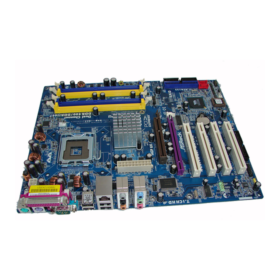
  • Seite 52 1. Einführung 1. Einführung 1. Einführung Wir danken Ihnen für den Kauf des ASRock 4CoreDual-SATA2 Motherboard, ein zuverlässiges Produkt, welches unter den ständigen, strengen Qualitätskontrollen von ASRock gefertigt wurde. Es bietet Ihnen exzellente Leistung und robustes Design, gemäß der Verpflichtung von ASRock zu Qualität und Halbarkeit.
  • Seite 53: Spezifikationen

    - 2 x Steckplätze für DDR - Unterstützt DDR400/333/266 - Max. 2GB Hybrid Booster - Schrittloser CPU-Frequenz-Kontrolle (siehe VORSICHT 5) - ASRock U-COP (siehe VORSICHT 6) - Boot Failure Guard (B.F.G. – Systemstartfehlerschutz) Erweiterungs- - 1 x PCI Express Grafik-Steckplätze (siehe VORSICHT 7) steckplätze - 1x AGP 8X-Steckplätze (siehe VORSICHT 8)
  • Seite 54 - Drehzahlmessung für CPU-Lüfter - Drehzahlmessung für Gehäuselüfter - CPU-Lüftergeräuschdämpfung - Spannungsüberwachung: +12V, +5V, +3.3V, Vcore ® ® Betriebssysteme - Unterstützt Microsoft Windows 2000 / XP / XP 64-Bit / Vista / Vista 64-Bit Zertifizierungen - FCC, CE, WHQL ASRock 4CoreDual-SATA2 Motherboard...
  • Seite 55 Motherboards! Permanente Beschädigung könnte die Folge sein! Der Mikrofoneingang dieses Motherboards unterstützt Stereo- und Mono-Modi. Der Audioausgang dieses Motherboards unterstützt 2- Kanal-, 4-Kanal- und 6-Kanal-Modi. Stellen Sie die richtige Verbindung anhand der Tabelle auf Seite 3 her. ASRock 4CoreDual-SATA2 Motherboard...
  • Seite 56 Vista Premium 2007 unterstützen. Die minimalen Hardwarevoraussetzungen entnehmen Sie bitte der nachstehenden Tabelle. Celeron D 326 Speicher 1 GB Systemspeicher (Premium) 512 MB, Single Channel (Basic) DX9.0 mit WDDM-Treiber mit 128 Bit-VGA-Speicher (Premium) mit 64 Bit-VGA-Speicher (Basic) ASRock 4CoreDual-SATA2 Motherboard...
  • Seite 57: Sicherheitshinweise Vor Der Montage

    Bevor Sie die 775-Pin CPU in den Sockel sitzen, prüfen Sie bitte, ob die CPU-Oberfläche sauber ist und keine der Kontakte verbogen sind. Setzen Sie die CPU nicht mit Gewalt in den Sockel, dies kann die CPU schwer beschädigen. ASRock 4CoreDual-SATA2 Motherboard...
  • Seite 58 775-Pin Sockel 775-Pin CPU Um die CPU ordnungsgemäß einsetzen zu können, richten Sie die zwei Orientierungskerben der CPU mit den beiden Markierungen des Sockels aus. Schritt 2-3. Drücken Sie die CPU vorsichtig in vertikaler Richtung in den Sockel. ASRock 4CoreDual-SATA2 Motherboard...
  • Seite 59 Schritt 4. Sockel schließen: Schritt 4-1. Drehen Sie die Ladeplatte auf den Kühlkörper (IHS). Schritt 4-2. Drücken Sie leicht auf die Ladeplatte und schließen Sie den Ladehebel. Schritt 4-3. Sichern Sie Ladehebel und Ladeplatte mithilfe des Hebelverschlusses. ASRock 4CoreDual-SATA2 Motherboard...
  • Seite 60 Uhrzeigersinn zu drehen, wird der Kühlkörper nicht ordnungsgemäß am Motherboard befestigt. Schritt 5. Schließen Sie den Lüfter an den CPU- Lüfteranschluss des Motherboards. Schritt 6. Befestigen Sie überschüssiges Kabel mit Band, um eine Störung des Lüfters oder Kontakt mit anderen Teilen zu vermeiden. ASRock 4CoreDual-SATA2 Motherboard...
  • Seite 61: Installation Der Speichermodule (Dimm)

    2.3 Installation der Speichermodule (DIMM) 2.3 Installation der Speichermodule (DIMM) 2.3 Installation der Speichermodule (DIMM) Das 4CoreDual-SATA2 Motherboard bietet zwei 184-polige DDR (Double Data Rate) DIMM Steckplätze, zwei 240-polige DDR2 DIMM Steckplätze und unterstützt Doppelkanal-Speichertechnologie. Für die Doppelkanalkonfiguration müssen Sie immer identische (selbe Marke, selbe Frequenz, selbe Größe und selber Chiptyp)
  • Seite 62: Einsetzen Eines Dimm-Moduls

    Steckplätze zu zwingen, führt dies zu dauerhaften Schäden am Mainboard und am DIMM-Modul. Schritt 3: Drücken Sie die DIMM-Module fest in die Steckplätze, so dass die Halteklammern an beiden Enden des Moduls einschnappen und das DIMM-Modul fest an Ort und Stelle sitzt. ASRock 4CoreDual-SATA2 Motherboard...
  • Seite 63: Einbau Einer Erweiterungskarte

    PCI-Slots: PCI-Slots werden zur Installation von Erweiterungskarten mit dem 32bit PCI-Interface genutzt. AGP-Slot: Der AGP-Steckplatz dient zur Installation einer Grafikkarte. Der ASRock AGP-Steckplatz hat speziell entwickelte Klammern, die die eingefügte Grafikkarte sicher festhalten. AGP Steckplatz ist für den Anschluss von AGP-Erweiterungskarten.
  • Seite 64: Einstellung Der Jumper

    2.5 “Surround Display” 2.5 “Surround Display” 2.5 “Surround Display” Dank ASRock patentierter PCI Express Grafik Technologie bietet dieses Motherboard Surround Display Aufrüstung. Mit interner AGP VGA oder PCI Express VGA-Erweiterungskarte können Sie Surround Display genießen. Für detaillierte Informationen, siehe folgendes Dokument auf beiliegender Support-CD: ..\ Surround Display Information...
  • Seite 65 Massenspeichergeräte. Die SATA1 SATA2 aktuelle SATAII-Schnittstelle ermöglicht eine Datenübertragungsrate bis 3,0 Gb/s. Serial ATA- (SATA-) Sie können beide Enden des Datenkabel SATA-Datenkabels entweder mit der SATA / SATAII- (Option) Festplatte oder dem SATAII-Anschluss am Mainboard verbinden. ASRock 4CoreDual-SATA2 Motherboard...
  • Seite 66 MPEG-Karten mit Ihrem System zu verbinden. Anschluss für Audio auf Dieses Interface zu einem der Gehäusevorderseite Audio-Panel auf der Vorderseite Ihres Gehäuses, ermöglicht (9-Pin HD_AUDIO1) Ihnen eine bequeme (siehe S.2 - Nr. 24) Anschlussmöglichkeit und Kontrolle über Audio-Geräte. ASRock 4CoreDual-SATA2 Motherboard...
  • Seite 67 Schließen Sie den Gehäuselautsprecher an (4-pin SPEAKER1) diesen Header an. (siehe S.2, Nr. 14) Gehäuselüfteranschluss Verbinden Sie das Gehäuselüfterkabel mit diesem (3-pin CHA_FAN1) Anschluss und passen Sie den (siehe S.2 - Nr. 15) schwarzen Draht dem Erdungsstift an. ASRock 4CoreDual-SATA2 Motherboard...
  • Seite 68 Beachten Sie bitte, dass Sie eine 12V-ATX-Netzteil Stromversorgung mit ATX 12- Volt-Stecker mit diesem (4-pin ATX12V1) Anschluss verbinden müssen, (siehe S.2 - Nr. 2) damit ausreichend Strom geliefert werden kann. Andernfalls reicht der Strom nicht aus, das System zu starten. ASRock 4CoreDual-SATA2 Motherboard...
  • Seite 69 Ende (A) des (Option) HDMI_SPDIF-Kabels mit dem HDMI_SPDIF-Anschluss am Motherboard. Schließen Sie dann das weiße Ende (B oder C) des HDMI_SPDIF-Kabels an den HDMI_SPDIF-Anschluss der HDMI-VGA-Karte an. A. Schwarzes Ende B. Weißes Ende (zweipolig) C. Weißes Ende (dreipolig) ASRock 4CoreDual-SATA2 Motherboard...
  • Seite 70 In der Abbildung sehen Sie ein Beispiel für einen falschen Anschluss: Hier wird versucht, das HDMI_SPDIF-Kabel mit dem Lüfteranschluss der PCI Express-VGA-Karte zu verbinden. Schauen Sie in die Dokumentation Ihrer VGA-Karte und informieren Sie sich schon im Vorfeld über die richtige Nutzung der Anschlüsse. ASRock 4CoreDual-SATA2 Motherboard...
  • Seite 71 DOS ausführbares Dienstprogramm. Auf der Internetseite von HITACHI finden Sie entsprechende Details: http://www.hitachigst.com/hdd/support/download.htm Die Beispiele oben dienen lediglich Ihrer Referenz. Die Steckbrückeneinstellungen können bei unterschiedlichen SATA II Festplatten verschiedener Hersteller abweichen. Aktualisierungen und ergänzende Informationen finden Sie auf der Internetseite des Herstellers. ASRock 4CoreDual-SATA2 Motherboard...
  • Seite 72 AII- Festplatten Festplatten Festplatten Festplatten Festplatten Das Motherboard 4CoreDual-SATA2 unterstützt Hot-Plug-Funktion für SATA / SATAII-Geräte. HINWEIS Was ist die Hot-Plug-Funktion? Wenn SATA / SATAII-Festplatten NICHT für RAID-Konfiguration eingestellt sind, werden sie “Hot-Plug” genannt: Ein Einfügen und Entfernen von SATA / SATAII-Festplatten, während das System in Betrieb ist und einwandfrei läuft.
  • Seite 73: Bit Mit Raid-Funktionen

    Setzen Sie die Option “SATA Operation Mode” (SATA-Betriebsmodus) auf [RAID]. SCHRITT 2: Erstellen Sie eine SATA / SATAII-Treiberdiskette. Legen Sie die ASRock Support-CD in Ihr optisches Laufwerk, um Ihr System hochzufahren. (Legen Sie zu diesem Zeitpunkt KEINE Diskette in das Diskettenlaufwerk ein!) Während des Selbsttests zu Beginn des Systemstarts drücken Sie die <F11>-...
  • Seite 74 64-Bit Betriebssystem mit RAID-Funktionalität installieren möchten, gehen Sie bitte wie folgt vor. SCHRITT 1: Konfigurieren Sie BIOS. Rufen Sie im BIOS-DIENSTPROGRAMM den Bildschirm „Erweitert“ und „IDE-Konfiguration“ auf. Setzen Sie die Option “SATA Operation Mode” (SATA-Betriebsmodus) auf [RAID]. ASRock 4CoreDual-SATA2 Motherboard...
  • Seite 75 Vista / Vista 64-Bit Betriebssystem auf Ihrem System zu installieren. Wenn die Frage “Wo möchten Sie Windows installieren?” erscheint, legen Sie bitte die ASRock Support CD in Ihr optisches Laufwerk ein. Klicken Sie anschließend die “Treiber laden”-Schaltfläche links ® ®...
  • Seite 76 AGP / PCI / PCIE-Bus in einem fixierten Modus, so dass der FSB in einer stabileren Übertaktungsumgebung arbeiten kann. Beziehen Sie sich auf die Warnung vor möglichen Overclocking-Risiken auf Seite 55, bevor Sie die Untied Overclocking-Technologie anwenden. ASRock 4CoreDual-SATA2 Motherboard...
  • Seite 77 ASSETUP.EXE im BIN-Verzeichnis der Support-CD, um die Menüs aufzurufen. Das Setup-Programm soll es Ihnen so leicht wie möglich machen. Es ist menügesteuert, d.h. Sie können in den verschiedenen Untermenüs Ihre Auswahl treffen und die Programme werden dann automatisch installiert. ASRock 4CoreDual-SATA2 Motherboard...
  • Seite 78 1. Introduction Merci pour votre achat d’une carte mère ASRock 4CoreDual-SATA2, une carte mère très fiable produite selon les critères de qualité rigoureux de ASRock. Elle offre des performances excellentes et une conception robuste conformément à l’engagement d’ASRock sur la qualité et la fiabilité au long terme.
  • Seite 79 - Max. 2Go L’accélérateur - Contrôle direct de la fréquence CPU (voir ATTENTION 5) hybride - ASRock U-COP (voir ATTENTION 6) - Garde d’échec au démarrage (B.F.G.) Slot d’extension - 1 x slot PCI Express Graphiques (voir ATTENTION 7) - 1 x slot AGP 8X (voir ATTENTION 8) - 4 x slots PCI ®...
  • Seite 80 - Tachéomètre ventilateur châssis - Ventilateur silencieux d’unité centrale - Monitoring de la tension: +12V, +5V, +3.3V, Vcore ® ® - Microsoft Windows 2000 / XP / XP 64-bit / Vista / Vista 64-bit Certifications - FCC, CE, WHQL ASRock 4CoreDual-SATA2 Motherboard...
  • Seite 81 Pour l’entrée microphone, cette carte mère supporte les deux modes stéréo et mono. Pour la sortie audio, cette carte mère supporte les modes 2-canaux, 4-canaux et 6-canaux. Veuillez vous référer au tableau en page 3 pour effectuer la bonne connexion. ASRock 4CoreDual-SATA2 Motherboard...
  • Seite 82 Unité centrale Celeron D 326 Mémoire mémoire système 1 Go (Premium) 512 Mo Canal simple (Basic) Adaptateur VGA DX9.0 avec pilote WDDM avec mémoire VGA 128bits (Premium) avec mémoire VGA 64bits (Basic) ASRock 4CoreDual-SATA2 Motherboard...
  • Seite 83 5. Lorsque vous placez les vis dans les orifices pour vis pour fixer la carte mère sur le châssis, ne serrez pas trop les vis ! Vous risquez sinon d’endommager la carte mère. ASRock 4CoreDual-SATA2 Motherboard...
  • Seite 84 Etape 2-1. Tenez le processeur par ses bords là où se trouvent des lignes noires Etape 2-2. Orientez le paquet avec le dissipateur thermique intégré (IHS) vers le haut. Repérez la broche 1 et les deux encoches d’orientation. ASRock 4CoreDual-SATA2 Motherboard...
  • Seite 85 Etape 4-2. Tout en appuyant doucement sur la plaque de chargement, engagez le levier de chargement Etape 4-3. Fixez le levier de chargement avec la languette de la plaque de chargement sous la languette de retenue du levier de chargement. ASRock 4CoreDual-SATA2 Motherboard...
  • Seite 86 Etape 6. Fixez la longueur de câble en excès avec du ruban adhésif pour vous assurer que le câble ne gênera pas le fonctionnement du ventilateur ou n’entrera pas en contact avec les autres composants. ASRock 4CoreDual-SATA2 Motherboard...
  • Seite 87 2.3 Installation des modules mémoire (DIMM) 2.3 Installation des modules mémoire (DIMM) La carte mère 4CoreDual-SATA2 comprend deux slots pour DIMM DDR 184 broches (Débit de données double) et deux slots pour DIMM DDR2 240 broches; elle prend en charge la technologie mémoire double voie (Dual Channel Memory). Pour la configuration double voie, il vous faut toujours installer des paires de DIMM DDR/DDR2 identiques (même marque, même vitesse, même taille et même type de puce) dans...
  • Seite 88 DIMM. Etape 3. Insérez fermement le module DIMM dans son emplacement jusqu’à ce que les clips de maintien situés aux deux extrémités se ferment complètement et que le module DIMM soit inséré correctement. ASRock 4CoreDual-SATA2 Motherboard...
  • Seite 89 PCI 32 bits. Slot AGP: Le slot AGP est utilisé pour installer une carte graphique. Le slot AGP ASRock utilise un design de fermoir spécial qui permet de fixer correctement la carte graphique insérée. L’emplacement AGP est utilisé...
  • Seite 90 2.5 “Surround Display” 2.5 “Surround Display” Grâce aux technologies PCI Express Graphiques brevetées d’ASRock, cette carte mère prend en charge la mise à niveau Affichage Surround. Avec la carte VGA AGP complémentaire externe et la carte PCI Express VGA, vous pouvez facilement profiter de la fonction Affichage Surround.
  • Seite 91 3,0 Go/s. Câble de données L’une des deux extrémités du Série ATA (SATA) câble de données SATA peut être connectée au disque dur (en option) SATA / SATAIIou au connecteur SATAII sur la carte mère. ASRock 4CoreDual-SATA2 Motherboard...
  • Seite 92 1. L’audio à haute définition (HDA) prend en charge la détection de fiche, mais le fil de panneau sur le châssis doit prendre en charge le HDA pour fonctionner correctement. Veuillez suivre les instructions dans notre manuel et le manuel de châssis afin installer votre système. ASRock 4CoreDual-SATA2 Motherboard...
  • Seite 93 (voir p.2 No. 15) Connecteur du ventilateur Veuillez connecter le câble de de l’UC ventilateur d’UC sur ce connecteur et brancher le fil (CPU_FAN1 br. 4) noir sur la broche de terre. (voir p.2 No. 5) ASRock 4CoreDual-SATA2 Motherboard...
  • Seite 94 SPDIF vers la carte VGA HDMI, (voir p.2 No. 23) et permettant au système de se connecter au un téléviseur numérique HDMI /un projecteur / un périphérique LCD. Veuillez brancher le connecteur HDMI_SPDIF de la carte VGA HDMI sur ce connecteur. ASRock 4CoreDual-SATA2 Motherboard...
  • Seite 95 HDMI_SPDIF de la carte VGA HDMI. (Le câble HDMI_SPDIF comporte deux extrémités blanches (2 broches et 3 broches). Veuillez choisir l’extrémité blanche appropriée en fonction du connecteur HDMI_SPDIF de la carte VGA HDMI que vous installez. ASRock 4CoreDual-SATA2 Motherboard...
  • Seite 96 SATAII. Western Digital Pour activer SATA 1.5 Go/s, raccourcir les broches 5 et 6. D’autre part, si vous voulez activer SATAII 3.0 Go/s, enlever le cavalier entre la broche 5 et la broche 6. SAMSUNG ASRock 4CoreDual-SATA2 Motherboard...
  • Seite 97 ETAPE 3 : Connectez l’une des extrémités du câble de données SATA sur le connecteur SATAII de la carte mère. ETAPE 4 : Connectez l’autre extrémité du câble de données SATA au disque dur SATA / SATAII. ASRock 4CoreDual-SATA2 Motherboard...
  • Seite 98 A / SAT T T T T AII Disques Durs SA Disques Durs SA A / SA La Carte Mère 4CoreDual-SATA2 supporte la fonction “Hot Plug” pour les périphériques SATA / SATAII. REMARQUE Qu’est-ce que la fonction « Hot Plug »? Si les disques durs SATA / SATAII ne sont pas en configuration RAID, l’action d’insérer et de retirer des disques SATA / SATAII alors que le...
  • Seite 99 B. Réglez l’option “SATA Operation Mode”« Mode de fonctionnement SATA » sur [RAID]. ETAP 2: Créez une disquette pilotes SATA / SATAII. A. Insérez le CD de soutien ASRock dans votre lecteur de disque optique pour démarrer votre système. (N’insérez AUCUNE disquette dans le lecteur de disquette pour l’instant!) B.
  • Seite 100 64-bits sur votre système. Lorsque vous voyez la page “Où souhaitez-vous installer Windows ?”, veuillez insérer le CD Support d’ ASRock dans votre lecteur optique, et cliquer sur le bouton “Charger le pilote” en bas à gauche pour charger les pilotes RAID VIA ®...
  • Seite 101 ® ® ® ® 2000 / Windows XP / Windows XP 64-bit / Windows Vista / Windows Vista 64-bit sur votre système. 1 0 1 1 0 1 1 0 1 1 0 1 1 0 1 ASRock 4CoreDual-SATA2 Motherboard...
  • Seite 102 Si le Menu principal n’apparaît pas automatiquement, localisez dans le CD technique le fichier “ASSETUP.EXE” dans le dossier BIN et double-cliquez dessus pour afficher les menus. 1 0 2 1 0 2 1 0 2 1 0 2 1 0 2 ASRock 4CoreDual-SATA2 Motherboard...
  • Seite 103: Contenuto Della Confezione

    Grazie per aver scelto una scheda madre ASRock 4CoreDual-SATA2, una scheda madre affidabile prodotta secondo i severi criteri di qualità ASRock. Le prestazioni eccellenti e il design robusto si conformano all’impegno di ASRock nella ricerca della qualità e della resistenza.
  • Seite 104 - Supporta DDR400/333/266 - Max. 2GB Booster ibrido - Stepless control per frequenza del processore (vedi ATTENZIONE 5) - ASRock U-COP (vedi ATTENZIONE 6) - Boot Failure Guard (B.F.G.) Slot di - 1 x slot PCI Express Grafica (vedi ATTENZIONE 7) espansione...
  • Seite 105 La procedura è eseguita a proprio rischio ed a proprie spese. Noi non possiamo essere ritenuti responsabili per possibili danni provocati dall’overclocking. 1 0 5 1 0 5 1 0 5 1 0 5 1 0 5 ASRock 4CoreDual-SATA2 Motherboard...
  • Seite 106 11. La Gestione Risorse per USB 2.0 funziona perfettamente con ® ® Microsoft Windows Vista 64-bit / Vista / XP 64 bit / XP SP1; SP2/ 2000 SP4. 1 0 6 1 0 6 1 0 6 1 0 6 1 0 6 ASRock 4CoreDual-SATA2 Motherboard...
  • Seite 107 1GB di memoria di sistema (Premium) 512MB ad un canale (Basic) DX9.0 con driver WDDM Con memoria VGA 128bit (Premium) Con memoria VGA 64bit (Basic) 1 0 7 1 0 7 1 0 7 1 0 7 1 0 7 ASRock 4CoreDual-SATA2 Motherboard...
  • Seite 108: Installazione

    5. Nell’usare i giraviti per fissare la scheda madre al telaio non serrare eccessivamente le viti! Altrimenti si rischia di danneggiare la scheda madre. 1 0 8 1 0 8 1 0 8 1 0 8 1 0 8 ASRock 4CoreDual-SATA2 Motherboard...
  • Seite 109 Fase 2. Inserire la CPU 775-Pin: Fase 2-1. Tenere la CPU dai bordi segnati con linee nere. 1 0 9 1 0 9 1 0 9 1 0 9 1 0 9 ASRock 4CoreDual-SATA2 Motherboard...
  • Seite 110 Fase 4-1. Ruotare la piastra di carico sull’IHS. Fase 4-2. Bloccare la leva di carico mentre si preme leggermente sulla piastra di carico. 1 1 0 1 1 0 1 1 0 1 1 0 1 1 0 ASRock 4CoreDual-SATA2 Motherboard...
  • Seite 111 Fase 6. fissare il cavo in eccesso con fascette per assicurare che il cavo non interferisca con il funzionamento della ventola o che venga a contatto con gli altri componenti. 1 1 1 1 1 1 1 1 1 1 1 1 1 1 1 ASRock 4CoreDual-SATA2 Motherboard...
  • Seite 112 2.3 Installazione dei moduli di memoria (DIMM) 2.3 Installazione dei moduli di memoria (DIMM) La scheda madre 4CoreDual-SATA2 fornisce due slot DDR (Double Data Rate) DIMM 184 pin e due slot DDR2 DIMM 240 pin, e supporta la tecnologia di memoria a doppio canale.
  • Seite 113 Inserire saldamente la DIMM nello slot fino a far scattare completamente in posizione i fermagli di ritegno alle due estremità e fino ad installare correttamente la DIMM nella sua sede. 1 1 3 1 1 3 1 1 3 1 1 3 1 1 3 ASRock 4CoreDual-SATA2 Motherboard...
  • Seite 114 32-bit. Slot AGP: Lo slot AGP serve all’installazione di schede grafiche. Lo slot AGP ASRock usa uno speciale gancio che permette di fissare in sede in modo sicuro la scheda grafica. lo slot AGP viene usato per installare le schede di espansione di AGP.
  • Seite 115 2.5 “Surround Display” 2.5 “Surround Display” Grazie alle tecnologie PCI Express Grafica brevettate da ASRock, questa scheda madre supporta l’aggiornamento del Surround Display. Con la scheda VGA AGP aggiuntiva esterna e la scheda VGA PCI Express, è possibile godersi facilmente i benefici della tecnologia Surround Display.
  • Seite 116 Entrambe le estremità del cavo dati SATA possono collegarsi (Opzionale) all’hard disk SATA / SATAII o al connettore SATAII sulla scheda madre. 1 1 6 1 1 6 1 1 6 1 1 6 1 1 6 ASRock 4CoreDual-SATA2 Motherboard...
  • Seite 117 È un’interfaccia per il cavo del pannello frontale pannello audio. Che consente connessione facile e controllo (9-pin HD_AUDIO1) dei dispositivi audio. (vedi p.2 item 24) 1 1 7 1 1 7 1 1 7 1 1 7 1 1 7 ASRock 4CoreDual-SATA2 Motherboard...
  • Seite 118 Collegare il cavo della ventolina telaio a questo connettore e far (3-pin CHA_FAN1) combaciare il filo nero al pin (vedi p.2 Nr. 15) terra. 1 1 8 1 1 8 1 1 8 1 1 8 1 1 8 ASRock 4CoreDual-SATA2 Motherboard...
  • Seite 119 (vedi p.2 Nr. 23) sistema di collegare dispositivi per TV digitale HDMI/proiettori/ LCD . Collegare il connettore HDMI_SPDIF della scheda VGA HDMI a questo header. 1 1 9 1 1 9 1 1 9 1 1 9 1 1 9 ASRock 4CoreDual-SATA2 Motherboard...
  • Seite 120 (2 pin e 3 pin). Scegliere l’estremità bianca adeguata in base al connettore HDMI_SPDIF della scheda HDMI VGA che si inserisce. 1 2 0 1 2 0 1 2 0 1 2 0 1 2 0 ASRock 4CoreDual-SATA2 Motherboard...
  • Seite 121 Se i pin 3 e 4 vengono cortocircuitati, verrà abilitato il SATA 1.5Gb/s. Diversamente, se si desidera abilitare il SATAII 3.0Gb/s, rimuovere i jumper dal pin 3 e dal pin 4. 1 2 1 1 2 1 1 2 1 1 2 1 1 2 1 ASRock 4CoreDual-SATA2 Motherboard...
  • Seite 122 A / SA dischi rigidi SA dischi rigidi SA A / SA La scheda madre 4CoreDual-SATA2 supporta la funzione di collegamento e scambio a caldo per i dispositivi SATA / SATAII. NOTA Che cosa è la funzione di collegamento a caldo? Se i dischi rigidi SATA / SATAII NON sono impostati per una configurazione RAID, è...
  • Seite 123 [RAID]. 2° PASSO: Creare un dischetto driver SATA / SATAII. Inserire il CD di supporto ASRock nel lettore ottico prima di accendere il sistema. (NON inserire nessun dischetto floppy nel drive in questo momento!) Durante la fase di POST, all’inzio del boot-up del sistema, premere il tasto <F11>.
  • Seite 124 , installare nuovamente i driver SATA / SATAII contenuti nel CD di supporto per eseguire anche l’installazione di “VIA RAID Tool” sul sistema. 1 2 4 1 2 4 1 2 4 1 2 4 1 2 4 ASRock 4CoreDual-SATA2 Motherboard...
  • Seite 125 64-bit sul sistema. Quando si vede la pagina “Where do you want to install Windows?” (Dove si vuole eseguire l’istallazione di Windows), inserire il CD di supporto ASRock nell’unità ottica e fare ® clic sul pulsante “Carica driver” , in basso a sinistra, per caricare i driver VIA ®...
  • Seite 126 Fare riferimento all’avviso di pagina 105 per i possibili rischi dell’overclocking prima di applicare la tecnologia Untied Overclocking Technology. 1 2 6 1 2 6 1 2 6 1 2 6 1 2 6 ASRock 4CoreDual-SATA2 Motherboard...
  • Seite 127 Menù principale. Se il Menù principale non appare automaticamente, posizionarsi sul file “ASSETUP.EXE” nel CESTINO del CD di supporto e cliccare due volte per visualizzare i menù. 1 2 7 1 2 7 1 2 7 1 2 7 1 2 7 ASRock 4CoreDual-SATA2 Motherboard...
  • Seite 128: Contenido De La Caja

    1. Introducción 1. Introducción Gracias por su compra de ASRock 4CoreDual-SATA2 placa madre, una placa de confianza producida bajo el control de calidad estricto y persistente. La placa madre provee realización excelente con un diseño robusto conforme al compromiso de calidad y resistencia de ASRock.
  • Seite 129 - Max. 2GB Amplificador - Stepless control de frecuencia de CPU (vea ATENCIÓN 5) Híbrido - ASRock U-COP (vea ATENCIÓN 6) - Protección de Falla de Inicio (B.F.G..) Ranuras de - 1 x ranuras PCI Express Gráfica (ver ATENCIÓN 7) Expansión...
  • Seite 130 - En conformidad con Microsoft ® Windows ® 2000 / XP / XP 64 bits / Vista / Vista 64 bits Certificaciones - FCC, CE, WHQL 1 3 0 1 3 0 1 3 0 1 3 0 1 3 0 ASRock 4CoreDual-SATA2 Motherboard...
  • Seite 131 2 canales, 4 canales y 6 canales. Consulte la tabla en la página 3 para una conexión correcta. 1 3 1 1 3 1 1 3 1 1 3 1 1 3 1 ASRock 4CoreDual-SATA2 Motherboard...
  • Seite 132 512 MB de un solo canal (Basic) DX9.0 con controlador WDDM con memoria VGA de 128 bit (Premium) con memoria VGA de 64 bit (Basic) 1 3 2 1 3 2 1 3 2 1 3 2 1 3 2 ASRock 4CoreDual-SATA2 Motherboard...
  • Seite 133: Instalación

    Para la instalación de la CPU Intel de (Placa de carga) (Cuerpo del socket) 775 agujas, siga los siguientes pasos. (Matriz de contacto) Introducción al socket de 775 agujas 1 3 3 1 3 3 1 3 3 1 3 3 1 3 3 ASRock 4CoreDual-SATA2 Motherboard...
  • Seite 134 Para insertarla correctamente, asegúrese de que las dos muescas de orientación de la CPU coinciden con las teclas de alineación del socket. 1 3 4 1 3 4 1 3 4 1 3 4 1 3 4 ASRock 4CoreDual-SATA2 Motherboard...
  • Seite 135 (Aplique el material termal de interfaz) Paso 1. Aplique el material termal de interfaz en el centro del IHS de la superficie del socket. 1 3 5 1 3 5 1 3 5 1 3 5 1 3 5 ASRock 4CoreDual-SATA2 Motherboard...
  • Seite 136 Paso 6. Fije el cable que sobre con un lazo para asegurarse de que el cable no interfiere en el funcionamiento del ventilador y tampoco entra en contacto con otros componentes. 1 3 6 1 3 6 1 3 6 1 3 6 1 3 6 ASRock 4CoreDual-SATA2 Motherboard...
  • Seite 137 2.3 Instalación de Memoria 2.3 Instalación de Memoria La placa base 4CoreDual-SATA2 proporciona dos ranuras DIMM DDR (Double Data Rate, es decir, Tasa doble de datos) de 184 contactos, dos ranuras DIMM DDRII de 240 contactos y es compatible con la Tecnología de memoria de canal dual.
  • Seite 138 Paso 3. Inserte la DIMM con firmeza dentro de la ranura hasta que los clips de sujeción de ambos lados queden completamente introducidos en su sitio y la DIMM se haya asentado apropiadamente. 1 3 8 1 3 8 1 3 8 1 3 8 1 3 8 ASRock 4CoreDual-SATA2 Motherboard...
  • Seite 139 Ranura PCI: Para instalar tarjetas de expansión que tienen 32-bit Interface PCI. Ranura AGP: Para instalar trajeta gráfica. La ranura AGP ASRock tiene un diseño especial de seguro para fijar con seguridad la tarjeta gráfica introducida. La ranura AGP se utiliza para instalar tarjetas de expansión AGP.
  • Seite 140 2.5 “Surround Display” 2.5 “Surround Display” Gracias a la tecnología PCI Express Gráfica patentada por ASRock, esta placa madre admite la actualización a Surround Display. Con las tarjetas complementarias externas VGA AGP y VGA PCI Express, podrá disfrutar de los beneficios que ofrece la característica Surround Display.
  • Seite 141 Ambos extremos del cable serie ATA (SATA) pueden conectarse al disco duro SATA / SATAII o la (Opcional) conexión de la placa base. 1 4 1 1 4 1 1 4 1 1 4 1 1 4 1 ASRock 4CoreDual-SATA2 Motherboard...
  • Seite 142 HDA para operar correctamente. Por favor, siga las instrucciones en nuestro manual y en el manual de chasis para instalar su sistema. 1 4 2 1 4 2 1 4 2 1 4 2 1 4 2 ASRock 4CoreDual-SATA2 Motherboard...
  • Seite 143 CPU a este conector y haga coincidir el cable negro (4-pin CPU_FAN1) con el conector de tierra. (ver p.2, N. 5) 1 4 3 1 4 3 1 4 3 1 4 3 1 4 3 ASRock 4CoreDual-SATA2 Motherboard...
  • Seite 144 TV Digital HDMI / proyectores / Dispositivos LCD. Conecte el conector HDMI_SPDIF de la tarjeta VGA HDMI a esta cabecera. 1 4 4 1 4 4 1 4 4 1 4 4 1 4 4 ASRock 4CoreDual-SATA2 Motherboard...
  • Seite 145 3 patillas) en el cable HDMI_SPDIF. Seleccione el extremo blanco adecuado según el conector HDMI_SPDIF de la tarjeta VGA HDMI que instale. 1 4 5 1 4 5 1 4 5 1 4 5 1 4 5 ASRock 4CoreDual-SATA2 Motherboard...
  • Seite 146 Si las patillas 3 y 4 están en corto, se activará SATA 1.5Gb/s. Por otro lado, si desea activar SATAII 3.0Gb/s, por favor retire los puentes de las patillas 3 y 4. 1 4 6 1 4 6 1 4 6 1 4 6 1 4 6 ASRock 4CoreDual-SATA2 Motherboard...
  • Seite 147 PASO 3: Conecte un extremo del cable de datos SATA al conector SATAII de la placa base. PASO 4: Conecte el otro extremo del cable de datos SATA al disco duro SATA / SATAII. 1 4 7 1 4 7 1 4 7 1 4 7 1 4 7 ASRock 4CoreDual-SATA2 Motherboard...
  • Seite 148 A / SAT T T T T AII HDDs SA HDDs SA A / SA La placa base 4CoreDual-SATA2 soporta la función de conexión en caliente para Dispositivos SATA / SATAII. NOTA ¿Qué es la función de conexión en caliente? Si los HDDs SATA / SATAII no están fijados para su configuración...
  • Seite 149 SATA) en [RAID]. PASO 2: Haga un Disquete de Controlador SATA / SATAII. Inserte el CD de soporte de ASRock en la unidad óptica de la unidad para iniciar el sistema. (NO inserte ningún disquete en la unidad de disco en este momento) Durante la comprobación inicial (POST) del sistema, pulse la tecla <F11>...
  • Seite 150 64 bits en el equipo. Cuando aparezca la página “Where do you want to install Windows?” (¿Dónde desea instalar Windows?), inserte el CD de soporte de ASRock en la unidad óptica y haga clic en el botón “Load Driver” (Cargar controlador) situado en la ®...
  • Seite 151 2000 / Windows ® ® ® XP / Windows XP 64 bits / Windows Vista / Windows Vista 64 bits en su sistema. 1 5 1 1 5 1 1 5 1 1 5 1 1 5 1 ASRock 4CoreDual-SATA2 Motherboard...
  • Seite 152 Principal automáticamente si «AUTORUN» está habilitado en su computadora. Si el Menú Principal no aparece automáticamente, localice y doble-pulse en el archivo “ASSETUP.EXE” para iniciar la instalación. 1 5 2 1 5 2 1 5 2 1 5 2 1 5 2 ASRock 4CoreDual-SATA2 Motherboard...

Inhaltsverzeichnis