Inhaltsverzeichnis
Werbung
Verfügbare Sprachen
Verfügbare Sprachen
Version 1.1
Published November 2017
Copyright©2017 ASRock INC. All rights reserved.
Copyright Notice:
No part of this documentation may be reproduced, transcribed, transmitted, or
translated in any language, in any form or by any means, except duplication of
documentation by the purchaser for backup purpose, without written consent of
ASRock Inc.
Products and corporate names appearing in this documentation may or may not
be registered trademarks or copyrights of their respective companies, and are used
only for identification or explanation and to the owners' benefit, without intent to
infringe.
Disclaimer:
Specifications and information contained in this documentation are furnished for
informational use only and subject to change without notice, and should not be
constructed as a commitment by ASRock. ASRock assumes no responsibility for
any errors or omissions that may appear in this documentation.
With respect to the contents of this documentation, ASRock does not provide
warranty of any kind, either expressed or implied, including but not limited to
the implied warranties or conditions of merchantability or fitness for a particular
purpose.
In no event shall ASRock, its directors, officers, employees, or agents be liable for
any indirect, special, incidental, or consequential damages (including damages for
loss of profits, loss of business, loss of data, interruption of business and the like),
even if ASRock has been advised of the possibility of such damages arising from any
defect or error in the documentation or product.
This device complies with Part 15 of the FCC Rules. Operation is subject to the following
two conditions:
(1) this device may not cause harmful interference, and
(2) this device must accept any interference received, including interference that
may cause undesired operation.
CALIFORNIA, USA ONLY
The Lithium battery adopted on this motherboard contains Perchlorate, a toxic substance
controlled in Perchlorate Best Management Practices (BMP) regulations passed by the
California Legislature. When you discard the Lithium battery in California, USA, please
follow the related regulations in advance.
"Perchlorate Material-special handling may apply, see www.dtsc.ca.gov/hazardouswaste/
perchlorate"
ASRock Website: http://www.asrock.com
Werbung
Inhaltsverzeichnis

Verwandte Anleitungen für ASROCK Z370 Extreme4


Inhaltszusammenfassung für ASROCK Z370 Extreme4
- Seite 1 (including damages for loss of profits, loss of business, loss of data, interruption of business and the like), even if ASRock has been advised of the possibility of such damages arising from any defect or error in the documentation or product.
- Seite 2 You are also entitled to have the goods repaired or replaced if the goods fail to be of acceptable quality and the failure does not amount to a major failure. If you require assistance please call ASRock Tel : +886-2-28965588 ext.123 (Standard International call charges apply) The terms HDMI™...
-
Seite 3: Motherboard-Layout
Z370 Extreme4 Motherboard Layout CPU_FAN1 ATX12V1 CPU_OPT/ W_PUMP HDMI1 USB 3.1 Gen2 T: USB31_TA_1 B: USB31_TC_1 USB 3.1 Gen1 Top: T: USB3 RJ-45 B: USB4 CHA_FAN1 USB3_TC_1 PCIE1 PCIE2 CMOS Battery Intel Z370 Purity PCIE3 Sound 4 PCIE4 PCIE5 BIOS_A1... - Seite 4 No. Description ATX 12V Power Connector (ATX12V1) CPU Fan Connector (CPU_FAN1) CPU Fan / Waterpump Fan Connector (CPU_OPT/W_PUMP) 2 x 288-pin DDR4 DIMM Slots (DDR4_A1, DDR4_B1) 2 x 288-pin DDR4 DIMM Slots (DDR4_A2, DDR4_B2) ATX Power Connector (ATXPWR1) USB 3.1 Gen1 Header (USB3_5_6) USB 3.1 Gen1 Header (USB3_7_8) Front Panel Type C USB 3.1 Gen1 Header (USB3_TC_1) SATA3 Connectors (SATA3_4_5)
- Seite 5 Z370 Extreme4 I/O Panel No. Description No. Description PS/2 Mouse/Keyboard Port (PS2_KB1) Optical SPDIF Out Port D-Sub Port USB 3.1 Gen1 Ports (USB3_34) LAN RJ-45 Port* USB 3.1 Gen2 Type-A Port (USB31_TA_1) Central / Bass (Orange) USB 3.1 Gen2 Type-C Port (USB31_TC_1)
- Seite 6 * There are two LEDs on each LAN port. Please refer to the table below for the LAN port LED indications. ACT/LINK LED SPEED LED LAN Port Activity / Link LED Speed LED Status Description Status Description No Link 10Mbps connection Blinking Data Activity Orange...
-
Seite 7: Chapter 1 Introduction
If you require technical support related to this mother- board, please visit our website for specific information about the model you are using. You may find the latest VGA cards and CPU support list on ASRock’s website as well. ASRock website http://www.asrock.com. -
Seite 8: Specifications
• Supports DDR4 4333+(OC)*/4000(OC)/3866(OC)/ 3800(OC)/3733(OC)/3600(OC)/3200(OC)/2933(OC)/2800 (OC)/2666/2400/2133 non-ECC, un-buffered memory * Please refer to Memory Support List on ASRock's website for more information. (http://www.asrock.com/) Gen Intel® CPU supports DDR4 up to 2666. • Supports ECC UDIMM memory modules (operate in non- ECC mode) • Max. - Seite 9 Z370 Extreme4 Graphics • Intel® HD Graphics Built-in Visuals and the VGA outputs can be supported only with processors which are GPU integrated. • Supports Intel® HD Graphics Built-in Visuals : Intel® Quick Sync Video with AVC, MVC (S3D) and MPEG-2 Full HW Encode1, Intel®...
- Seite 10 - Direct Drive Technology - PCB Isolate Shielding - Impedance Sensing on Front Out port - Individual PCB Layers for R/L Audio Channel - RGB LED - 15μ Gold Audio Connector • Supports DTS Connect • Gigabit LAN 10/100/1000 Mb/s • Giga PHY Intel®...
- Seite 11 M.2 PCI Express module up to Gen3 x4 (32 Gb/s)** ** Supports Intel® Optane Technology ** Supports NVMe SSD as boot disks ** Supports ASRock U.2 Kit Connector • 1 x COM Port Header • 1 x TPM Header • 1 x Power LED and Speaker Header...
- Seite 12 • Voltage monitoring: +12V, +5V, +3.3V, CPU Vcore, DRAM, VPPM, PCH 1.0V, VCCSA, VCCST • Microsoft® Windows® 10 64-bit Certifica- • FCC, CE tions • ErP/EuP ready (ErP/EuP ready power supply is required) * For detailed product information, please visit our website: http://www.asrock.com...
- Seite 13 Z370 Extreme4 Please realize that there is a certain risk involved with overclocking, including adjusting the setting in the BIOS, applying Untied Overclocking Technology, or using third-party overclocking tools. Overclocking may affect your system’s stability, or even cause damage to the components and devices of your system.
-
Seite 14: Chapter 2 Installation
Chapter 2 Installation This is an ATX form factor motherboard. Before you install the motherboard, study the configuration of your chassis to ensure that the motherboard fits into it. Pre-installation Precautions Take note of the following precautions before you install motherboard components or change any motherboard settings. -
Seite 15: Installing The Cpu
Z370 Extreme4 2.1 Installing the CPU 1. Before you insert the 1151-Pin CPU into the socket, please check if the PnP cap is on the socket, if the CPU surface is unclean, or if there are any bent pins in the socket. Do not force to insert the CPU into the socket if above situation is found. - Seite 17 Z370 Extreme4 Please save and replace the cover if the processor is removed. The cover must be placed if you wish to return the motherboard for after service.
- Seite 18 2.2 Installing the CPU Fan and Heatsink...
- Seite 19 Z370 Extreme4 2.3 Installing Memory Modules (DIMM) This motherboard provides four 288-pin DDR4 (Double Data Rate 4) DIMM slots, and supports Dual Channel Memory Technology. 1. For dual channel configuration, you always need to install identical (the same brand, speed, size and chip-type) DDR4 DIMM pairs.
- Seite 21 Z370 Extreme4 2.4 Expansion Slots (PCI Express Slots) There are 6 PCI Express slots on the motherboard. Before installing an expansion card, please make sure that the power supply is switched off or the power cord is unplugged. Please read the documentation of the expansion card and make necessary hardware settings for the card before you start the installation.
- Seite 22 2.5 Jumpers Setup The illustration shows how jumpers are setup. When the jumper cap is placed on the pins, the jumper is “Short”. If no jumper cap is placed on the pins, the jumper is “Open”. Clear CMOS Jumper Short: Clear CMOS (CLRCMOS1) Open: Default 2-pin Jumper...
- Seite 23 Z370 Extreme4 2.6 Onboard Headers and Connectors Onboard headers and connectors are NOT jumpers. Do NOT place jumper caps over these headers and connectors. Placing jumper caps over the headers and connectors will cause permanent damage to the motherboard. System Panel Header...
- Seite 24 Power LED and Speaker Please connect the SPEAKER DUMMY Header chassis power LED and DUMMY (7-pin SPK_PLED1) the chassis speaker to this (see p.1, No. 15) header. PLED+ PLED+ PLED- Serial ATA3 Connectors These eight SATA3 (SATA3_4_5: connectors support SATA see p.1, No.
- Seite 25 Z370 Extreme4 USB 3.1 Gen1 Headers There are two headers on Vbus Vbus Vbus IntA_PB_SSRX- (19-pin USB3_5_6) this motherboard. Each IntA_PA_SSRX- IntA_PB_SSRX+ IntA_PA_SSRX+ (see p.1, No. 7) USB 3.1 Gen1 header can IntA_PB_SSTX- IntA_PA_SSTX- IntA_PB_SSTX+ (19-pin USB3_7_8) support two ports.
- Seite 26 Chassis Fan Connectors Please connect fan cables (4-pin CHA_FAN1) to the fan connectors and (see p.1, No. 27) match the black wire to FAN_SPEED_CONTROL CHA_FAN_SPEED the ground pin. FAN_VOLTAGE (4-pin CHA_FAN2) FAN_VOLTAGE (see p.1, No. 22) FAN_SPEED FAN_SPEED_CONTROL Chassis Optional/Water This motherboard FAN_VOLTAGE Pump Fan Connector...
- Seite 27 Z370 Extreme4 ATX 12V Power This motherboard Connector provides an 8-pin ATX (8-pin ATX12V1) 12V power connector. To (see p.1, No. 1) use a 4-pin ATX power supply, please plug it along Pin 1 and Pin 5. Thunderbolt AIC Please connect a Thunderbolt™...
- Seite 28 2.7 M.2 WiFi/BT Module Installation Guide (M2_3) The M.2 Socket (Key E) supports type 2230 WiFi/BT module. Installing the WiFi/BT module Step 1 Prepare a type 2230 WiFi/BT module and the screw. Step 2 Find the nut location to be used. PCB Length: 3cm Module Type: Type2230 Step 3...
- Seite 29 Z370 Extreme4 Step 4 Tighten the screw with a screwdriver to secure the module into place. Please do not overtighten the screw as this might damage the module.
- Seite 30 2.8 M.2_SSD (NGFF) Module Installation Guide (M2_1 and M2_2) The M.2, also known as the Next Generation Form Factor (NGFF), is a small size and versatile card edge connector that aims to replace mPCIe and mSATA. The Ultra M.2 Sockets (M2_1 and M2_2) support SATA3 6.0 Gb/s module and M.2 PCI Express module up to Gen3 x4 (32 Gb/s).
- Seite 31 Z370 Extreme4 Step 3 Move the standoff based on the module type and length. The standoff is placed at the nut location D by default. Skip Step 3 and 4 and go straight to Step 5 if you are going to use the default nut.
- Seite 32 M.2_SSD (NGFF) Module Support List Vendor Interface ADATA SATA3 AXNS330E-32GM-B ADATA SATA3 AXNS381E-128GM-B ADATA SATA3 AXNS381E-256GM-B ADATA SATA3 ASU800NS38-256GT-C ADATA SATA3 ASU800NS38-512GT-C ADATA PCIe3 x4 ASX7000NP-128GT-C ADATA PCIe3 x4 ASX8000NP-256GM-C ADATA PCIe3 x4 ASX7000NP-256GT-C ADATA PCIe3 x4 ASX8000NP-512GM-C ADATA PCIe3 x4 ASX7000NP-512GT-C Apacer PCIe3 x4...
- Seite 33 Z370 Extreme4 TEAM PCIe3 x4 TM8FP2240G0C101 TEAM PCIe3 x4 TM8FP2480GC110 Transcend SATA3 TS256GMTS400 Transcend SATA3 TS512GMTS600 Transcend SATA3 TS512GMTS800 V-Color SATA3 VLM100-120G-2280B-RD V-Color SATA3 VLM100-240G-2280RGB V-Color SATA3 VSM100-240G-2280 V-Color SATA3 VLM100-240G-2280B-RD SATA3 WDS100T1B0B-00AS40 SATA3 WDS240G1G0B-00RC30 PCIe3 x4 WDS256G1X0C-00ENX0 (NVME) PCIe3 x4 WDS512G1X0C-00ENX0 (NVME) For the latest updates of M.2_SSD (NFGG) module support list, please visit our website for...
- Seite 34 2.9 ASRock RGB LED ASRock RGB LED is a lighting control utility specifically designed for unique individuals with sophisticated tastes to build their own stylish colorful lighting system. Simply by connecting the LED strip, you can customize various lighting schemes and patterns, including Static, Breathing, Strobe, Cycling, Music, Wave and more.
- Seite 35 ASRock RGB LED Utility Now you can adjust the RGB LED color through the ASRock RGB LED utility. Download this utility from the ASRock Live Update & APP Shop and start coloring your PC style your way! Drag the tab to customize your preference.
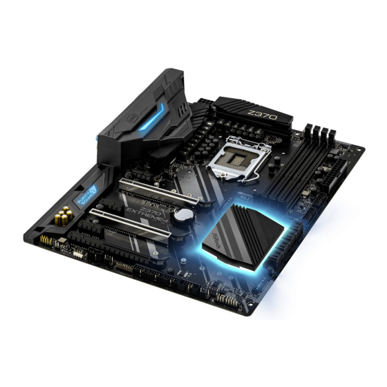
- Seite 36 1 Einleitung Vielen Dank, dass Sie sich für das ASRock Z370 Extreme4 entschieden haben – ein zuverlässiges Motherboard, das konsequent unter der strengen Qualitätskontrolle von ASRock hergestellt wurde. Es liefert ausgezeichnete Leistung mit robustem Design, das ASRock Streben nach Qualität und Beständigkeit erfüllt.
-
Seite 37: Technische Daten
-Prozessoren (Sockel 1151) der 8. Generation • Digi Power design • 12-Leistungsphasendesign • Unterstützt Intel® Turbo Boost 2.0-Technologie • Unterstützt CPUs mit freiem Multiplikator der Intel® K-Serie • Unterstützt ASRock BCLK-Übertaktung (voller Bereich) ® • Intel Z370 Chipsatz Speicher • Dualkanal-DDR4-Speichertechnologie • 4 x DDR4-DIMM-Steckplätze... - Seite 38 Grafikkarte • Integrierte Intel® UHD Graphics-Visualisierung und VGA- Ausgänge können nur mit Prozessoren unterstützt werden, die GPU-integriert sind. • Unterstützt integrierte Intel® UHD Graphics-Visualisierung: Intel® Quick Sync Video mit AVC, MVC (S3D) und MPEG- 2 Full HW Encode1, Intel® InTru 3D, Intel®...
- Seite 39 Z370 Extreme4 - Direct Drive Technology - PCB-isolierte Abschirmung - Impedanzerkennung am vorderen Ausgang - Individuelle PCB-Layer für rechten/linken Audiokanal - RGB-LED - 15-μ-Gold-Audioanschluss • Unterstützt DTS Connect • Gigabit LAN 10/100/1000 Mb/s • Giga PHY Intel® I219V • Unterstützt Wake-On-LAN • Unterstützt Schutz gegen Blitzschlag/elektrostatische Entladung...
- Seite 40 2230/2242/2260/2280/22110-M.2-SATA-III-6,0-Gb/s-Modul und M.2-PCI-Express-Modul bis Gen. 3 x 4 (32 Gb/s)** ** Unterstützt Intel® Optane -Technologie ** Unterstützt NVMe-SSD als Bootplatte ** Unterstützt ASRock U.2-Kit Anschluss • 1 x COM-Anschluss-Stiftleiste • 1 x TPM-Stiftleiste • 1 x Betrieb-LED- und Lautsprecher-Stiftleiste • 1 x RGB-LED-Stiftleiste * Unterstützt insgesamt bis zu 12 V/3 A, 36-W-LED-Streifen...
- Seite 41 Zertifizierun- • ErP/EuP ready (ErP/EuP ready-Netzteil erforderlich) * Detaillierte Produktinformationen finden Sie auf unserer Webseite: http://www.asrock.com Bitte beachten Sie, dass mit einer Übertaktung, zu der die Anpassung von BIOS-Einstellungen, die Anwendung der Untied Overclocking Technology oder die Nutzung von Übertaktungswerkzeugen von Drittanbietern zählen, bestimmte Risiken verbunden sind.
-
Seite 42: Jumpereinstellung
1.3 Jumpereinstellung Die Abbildung zeigt, wie die Jumper eingestellt werden. Wenn die Jumper-Kappe auf den Kontakten angebracht ist, ist der Jumper „kurzgeschlossen“. Wenn keine Jumper- Kappe auf den Kontakten angebracht ist, ist der Jumper „offen“. CMOS-löschen-Jumper Kurzgeschlossen: CMOS löschen (CLRCMOS1) Offen: Standard 2-poliger Jumper (siehe S. -
Seite 43: Integrierte Stiftleisten Und Anschlüsse
Z370 Extreme4 1.4 Integrierte Stiftleisten und Anschlüsse Integrierte Stiftleisten und Anschlüsse sind KEINE Jumper. Bringen Sie KEINE Jumper-Kappen an diesen Stiftleisten und Anschlüssen an. Durch Anbringen von Jumper-Kappen an diesen Stiftleisten und Anschlüssen können Sie das Motherboard dauerhaft beschädigen. Systemblende-Stiftleiste... - Seite 44 Betrieb-LED- und Bitte verbinden Sie SPEAKER DUMMY Lautsprecher-Stiftleiste die Betrieb-LED des DUMMY (7-polig, SPK_PLED1) Gehäuses und den (siehe S. 1, Nr. 15) Gehäuselautsprecher mit dieser Stiftleiste. PLED+ PLED+ PLED- Serial-ATA-III-Anschlüsse Diese acht SATA-III- (SATA3_4_5: Anschlüsse unterstützen siehe S. 1, Nr. 10) SATA-Datenkabel für interne (SATA3_2_3: Speichergeräte mit einer Date...
- Seite 45 Z370 Extreme4 USB 3.1 Gen1-Stiftleisten Es gibt zwei Stiftleisten Vbus Vbus Vbus IntA_PB_SSRX- (19-polig, USB3_5_6) an diesem Motherboard. IntA_PA_SSRX- IntA_PB_SSRX+ IntA_PA_SSRX+ (siehe S. 1, Nr. 7) Jede USB 3.1 Gen1- IntA_PB_SSTX- IntA_PA_SSTX- IntA_PB_SSTX+ (19-polig, USB3_7_8) Stiftleiste kann zwei Ports IntA_PA_SSTX+ IntA_PB_D- (siehe S.
- Seite 46 Gehäuselüfteranschlüsse Bitte verbinden Sie die (4-polig, CHA_FAN1) Lüfterkabel mit den (siehe S. 1, Nr. 27) Lüfteranschlüssen; der FAN_SPEED_CONTROL CHA_FAN_SPEED schwarze Draht gehört FAN_VOLTAGE zum Erdungskontakt. (4-polig, CHA_FAN2) FAN_VOLTAGE (siehe S. 1, Nr. 22) FAN_SPEED FAN_SPEED_CONTROL Optionales-Gehäuse-/ Dieses Motherboard bietet einen FAN_VOLTAGE Wasserpumpen- 4-poligen Wasserkühlung-Ge-...
- Seite 47 Z370 Extreme4 ATX-12-V-Netzanschluss Dieses Motherboard bietet (8-polig, ATX12V1) einen 8-poligen ATX-12-V-Net- (siehe S. 1, Nr. 1) zanschluss. Bitte schließen Sie es zur Nutzung eines 4-poligen ATX-Netzteils entlang Kontakt 1 und Kontakt 5 an. Thunderbolt- Bitte verbinden Sie eine Erweiterungskarten Thunderbolt™-Erweiterungskarte anschlüsse...
-
Seite 48: Contenu De L'emballage
Si vous avez besoin d’une assistance technique pour votre carte mère, veuillez visiter notre site Internet pour plus de détails sur le modèle que vous utilisez. La liste la plus récente des cartes VGA et des processeurs pris en charge est également disponible sur le site Internet de ASRock. Site Internet ASRock http://www.asrock.com. -
Seite 49: Spécifications
• Alimentation à 12 phases • Prend en charge la technologie Intel® Turbo Boost 2.0 • Prend en charge les processeurs débloqués de la série K Intel® • Prend en charge l’ o verclocking ASRock BCLK Full-range ® Chipset • Intel Z370 Mémoire... - Seite 50 Graphiques • La technologie Intel® UHD Graphics Built-in Visuals et les sorties VGA sont uniquement prises en charge par les processeurs intégrant un contrôleur graphique. • Prend en charge la technologie Intel® UHD Graphics Built- in Visuals : Intel® Quick Sync Video avec AVC, MVC (S3D) et MPEG-2 Full HW Encode1, Intel®...
- Seite 51 Z370 Extreme4 - Technologie Direct Drive - Blindage isolant PCB - Détection d'impédance sur le port de sortie avant - Couches de PCB individuelles pour canal audio D/G - LED RVB - Connecteur audio or 15μ • Prend en charge DTS Connect Réseau...
- Seite 52 M.2 PCI Express jusqu'à Gen3 x4 (32 Go/s)** ** Prend en charge Intel® Optane Technology ** Prend en charge les SSD NVMe comme disques de démarrage ** Prend en charge le kit ASRock U.2 Connecteur • 1 x embase pour port COM • 1 x embase TPM • 1 x prise DEL d’alimentation et haut-parleur...
- Seite 53 • FCC, CE • ErP/EuP Ready (alimentation ErP/EuP ready requise) * pour des informations détaillées de nos produits, veuillez visiter notre site : http://www.asrock.com Il est important de signaler que l’ o verclocking présente certains risques, incluant des modifi- cations du BIOS, l’ a pplication d’une technologie d’ o verclocking déliée et l’utilisation d’ o utils d’...
- Seite 54 1.3 Configuration des cavaliers (jumpers) L’illustration ci-dessous vous renseigne sur la configuration des cavaliers (jumpers). Lorsque le capuchon du cavalier est installé sur les broches, le cavalier est « court- circuité ». Si le capuchon du cavalier n’ e st pas installé sur les broches, le cavalier est « ouvert ».
- Seite 55 Z370 Extreme4 1.4 Embases et connecteurs de la carte mère Les embases et connecteurs situés sur la carte NE SONT PAS des cavaliers. Ne placez JAMAIS de capuchons de cavaliers sur ces embases ou connecteurs. Placer un capuchon de cavalier sur ces embases ou connecteurs endommagera irrémédiablement votre carte mère.
- Seite 56 Prise DEL d’alimentation Veuillez brancher la DEL SPEAKER DUMMY et haut-parleur d'alimentation du châssis DUMMY (SPK_PLED1 à 7 broches) et le haut-parleur du (voir p.1, No. 15) châssis sur ce connecteur. PLED+ PLED+ PLED- Connecteurs Serial ATA3 Ces huit connecteurs SATA3 (SATA3_4_5: sont compatibles avec les voir p.1, No.
- Seite 57 Z370 Extreme4 Embases USB 3.1 Gen1 Cette carte mère comprend Vbus Vbus Vbus IntA_PB_SSRX- (USB3_5_6 à 19 broches) deux connecteurs. Chaque IntA_PA_SSRX- IntA_PB_SSRX+ IntA_PA_SSRX+ (voir p.1, No. 7) embase USB 3.1 Gen1 peut IntA_PB_SSTX- IntA_PA_SSTX- IntA_PB_SSTX+ (USB3_7_8 à 19 broches)
- Seite 58 Connecteurs du ventila- Veuillez brancher les câbles teur du châssis du ventilateur sur les (CHA_FAN1 à 4 broches) connecteurs du ventilateur, FAN_SPEED_CONTROL (voir p.1, No. 27) puis reliez le fil noir à la CHA_FAN_SPEED FAN_VOLTAGE broche de mise à terre. (CHA_FAN2 à...
- Seite 59 Z370 Extreme4 Connecteur d’alimentation Cette carte mère est dotée d’un ATX 12V connecteur d’alimentation ATX (ATX12V1 à 8 broches) 12V à 8 broches. Pour utiliser (voir p.1, No. 1) une alimentation ATX à 4 broches, veuillez effectuer les branchements sur la Broche 1 et la Broche 5.
-
Seite 60: Contenuto Della Confezione
Web di ASRock senza ulteriore preavviso. Per il supporto tecnico correlato a questa scheda madre, visitare il nostro sito Web per informazioni specifiche relative al modello attualmente in uso. - Seite 61 (OC)/3800(OC)/3733(OC)/3600(OC)/3200(OC)/2933(OC)/ 2800(OC)/2666/2400/2133 non-ECC, un-buffered * Per maggiori informazioni fare riferimento all'elenco dei supporti di memoria sul sito di ASRock. (http://www.asrock.com/) Gen Intel® CPU supporta DDR4 fino a 2666. • Supporta moduli di memoria ECC UDIMM (funziona in modalità non ECC) • Capacità...
- Seite 62 Grafica • La videografica integrata della scheda video UHD Intel® e le uscite VGA possono essere supportate soltanto con processori con GPU integrata. • Supporta la videografica integrata della scheda video UHD Intel®: Intel® Quick Sync Video con AVC, MVC (S3D) e MPEG- 2 Full HW Encode1, Intel®...
- Seite 63 Z370 Extreme4 - Tecnologia Direct Drive - Schermatura isolata PCB - Sensore impedenza sulla porta di uscita anteriore - Layer PCB individuali per canali audio R/L - LED RGB - Connettore audio dorato 15 μ • Supporta DTS Connect • LAN Gigabit 10/100/1000 Mb/s • Giga PHY Intel®...
- Seite 64 6,0 Gb/s di tipo 2230/2242/2260/2280/22110 ed il modulo M.2 PCI Express fino a Gen3 x4 (32 Gb/s)** ** Supporta la tecnologia Intel® Optane ** Supporto di SSD NVMe come disco d’avvio ** Supporta kit ASRock U.2 Connettore • 1 x connettore porta COM • 1 x connettore TPM • 1 x connettore LED alimentazione e altoparlante...
- Seite 65 • FCC, CE • ErP/EuP Ready (è necessaria alimentazione ErP/EuP ready) * Per informazioni dettagliate sul prodotto, visitare il nostro sito Web: http://www.asrock.com Prestare attenzione al potenziale rischio previsto nella pratica di overclocking, inclusa la regolazione delle impostazioni nel BIOS, l'applicazione di tecnologia di Untied Overclocking o l'utilizzo di strumenti di overclocking di terze parti.
- Seite 66 1.3 Impostazione jumper L'illustrazione mostra in che modo vengono impostati i jumper. Quando il cappuccio del jumper è posizionato sui pin, il jumper è "cortocircuitato". Se sui pin non è posizionato alcun cappuccio del jumper, il jumper è "aperto". Jumper per azzerare la CMOS Cortocircuitato: Azzerare la CMOS (CLRCMOS1) Aperto: Predefinito...
- Seite 67 Z370 Extreme4 1.4 Header e connettori su scheda Gli header e i connettori sulla scheda NON sono jumper. NON posizionare cappucci del jumper su questi header e connettori. Il posizionamento di cappucci del jumper su header e connettori provocherà danni permanenti alla scheda madre.
- Seite 68 Connettore LED Collegare i LED alimen- SPEAKER DUMMY alimentazione e tazione e l’altoparlante a DUMMY altoparlante questo connettore. (SPK_PLED1 a 7 pin) (vedere pag. 1, n. 15) PLED+ PLED+ PLED- Connettori Serial ATA3 Questi otto connettori SATA3 (SATA3_4_5: supportano cavi di trasmissione vedere pag.
- Seite 69 Z370 Extreme4 Header USB 3.1 Gen1 Ci sono due connettori su Vbus Vbus Vbus IntA_PB_SSRX- (USB3_5_6 a 19 pin) questa scheda madre. Ciascun IntA_PA_SSRX- IntA_PB_SSRX+ IntA_PA_SSRX+ (vedere pag. 1, n. 7) header USB 3.1 Gen1 può IntA_PB_SSTX- IntA_PA_SSTX- IntA_PB_SSTX+ (USB3_7_8 19 pin) supportare due porte.
- Seite 70 Connettori ventola telaio Collegare i cavi della (CHA_FAN1 a 4 pin) ventola ai connettori della (vedere pag. 1, n. 27) ventola e far corrispondere FAN_SPEED_CONTROL CHA_FAN_SPEED il filo nero al pin di terra. FAN_VOLTAGE (CHA_FAN2 a 4 pin) FAN_VOLTAGE FAN_SPEED (vedere pag.
- Seite 71 Z370 Extreme4 Connettore di Questa scheda madre è dotata alimentazione ATX di un connettore di alimen- da 12 V tazione ATX da 12 V a 8 pin. (ATX12V1 a 8 pin) Per utilizzare un'alimentazione (vedere pag. 1, n. 1) ATX a 4 pin, collegarla lungo il pin 1 e il pin 5.
-
Seite 72: Contenido Del Paquete
Si esta documentación sufre alguna modificación, la versión actualizada estará disponible en el sitio web de ASRock sin previo aviso. Si necesita asistencia técnica relacionada con esta placa base, visite nuestro sitio web para obtener información específica sobre el modelo que esté... -
Seite 73: Especificaciones
(OC)/3800(OC)/3733(OC)/3600(OC)/3200(OC)/2933(OC)/ 2800(OC)/2666/2400/2133 no ECC. * Para obtener más información, consulte la lista de memorias compatibles en el sitio web de ASRock. (http://www.asrock.com/) * CPU Intel® de 8 generación compatible con DDR4 de hasta 2666. • Admite módulos de memoria UDIMM ECC (funcionamiento en modo no ECC) • Capacidad máxima de memoria del sistema: 64GB... - Seite 74 Gráficos • Intel® UHD Graphics Built-in Visuals y las salidas de VGA son compatibles únicamente con procesadores con GPU integrado. • Admite Intel® UHD Graphics Built-in Visuals: Intel® Quick Sync Video con AVC, MVC (S3D) y MPEG-2 Full HW Encode1, Intel® InTru 3D, Intel®...
- Seite 75 Z370 Extreme4 - Tecnología Direct Drive - Protección de aislamiento PCB - Detección de impedancia en el puerto de salida frontal - Capas PCB individuales para canal de audio D/I - LED RGB - Conector de audio dorado de 15μ...
- Seite 76 ** Compatible con la tecnología Optane de Intel® ** Admite unidad de estado sólido de NVMe como disco de arran- ** Admite el kit U.2 de ASRock Conector • 1 x Base de conexiones de puerto COM • 1 x Conector TPM • 1 x LED de alimentación y base de conexiones para el altavoz...
- Seite 77 • Preparado para ErP/EuP (se necesita una fuente de alimentac- ión preparada para ErP/EuP) * Para obtener información detallada del producto, visite nuestro sitio Web: http://www.asrock.com Tenga en cuenta que hay un cierto riesgo implícito en las operaciones de overclocking, incluido el ajuste de la BIOS, aplicando la tecnología de overclocking liberada o utilizando las herrami-...
- Seite 78 1.3 Instalación de los puentes La instalación muestra cómo deben instalarse los puentes. Cuando la tapa de puente se coloca en los contactos, el puente queda “Corto”. Si no coloca la tapa de puente en los contactos, el puente queda “Abierto”. Puente de borrado de CMOS Corto: Borrado de CMOS (CLRCMOS1)
- Seite 79 Z370 Extreme4 1.4 Conectores y cabezales incorporados Los cabezales y conectores incorporados NO son puentes. NO coloque tapas de puente sobre estos cabezales y conectores. Si coloca tapas de puente sobre los cabezales y conectores dañará de forma permanente la placa base.
- Seite 80 LED de alimentación y Conecte el LED de ali- SPEAKER DUMMY base de conexiones para la mentación del chasis y el DUMMY altavoz altavoz del chasis a esta (SPK_PLED1 de 7 base de conexiones. contactos) PLED+ (consulte la pág.1, Nº 15) PLED+ PLED- Conectores Serie ATA3...
- Seite 81 Z370 Extreme4 Cabezales USB 3.1 Gen1 Hay dos bases de Vbus Vbus Vbus IntA_PB_SSRX- (USB3_5_6 de 19 conexiones en esta placa IntA_PA_SSRX- IntA_PB_SSRX+ IntA_PA_SSRX+ contactos) base. Cada cabezal USB 3.1 IntA_PB_SSTX- IntA_PA_SSTX- IntA_PB_SSTX+ (consulte la pág.1, Nº 7) Gen1 admite dos puertos.
- Seite 82 Conectores para el venti- Conecte los cables del lador del chasis ventilador a los conectores del (CHA_FAN1 de 4 contac- ventilador y haga coincidir el FAN_SPEED_CONTROL CHA_FAN_SPEED tos) cable negro con el contacto FAN_VOLTAGE (consulte la pág.1, Nº 27) de conexión a tierra. (CHA_FAN2 de 4 contac- FAN_VOLTAGE FAN_SPEED...
- Seite 83 Z370 Extreme4 Conector de alimentación Esta placa base contiene un ATX de 12V conector de alimentación ATX (ATX12V1 de 8 contactos) de 12V y 8 contactos. Para uti- (consulte la pág.1, Nº 1) lizar una toma de alimentación ATX de 4 contactos, conéctela en los contactos del 1 al 5.
-
Seite 84: Комплект Поставки
уведомления. При необходимости технической поддержки, связанной с материнской платой, посетите веб-сайт и найдите на нем информацию о модели используемой вами материнской платы. На веб-сайте ASRock также можно найти самый последний перечень поддерживаемых VGA-карт и ЦП. Веб-сайт ASRock http://www.asrock.com. 1.1. Комплект поставки... -
Seite 85: Технические Характеристики
1151) • Digi Power design • Система питания 12 • Поддерживается технология Intel® Turbo Boost 2.0 • Поддержка процессоров Intel® серии K с разблокированным множителем • Поддержка полного разгона процессора ASRock BCLK ® Чипсет • Intel Z370 Память • Двухканальная память DDR4 • 4 гнезда... - Seite 86 Графическая • Встроенный видеоадаптер Intel® UHD Graphics и выходы подсистема VGA поддерживаются только при использовании ЦП со встроенными графическими процессорами. • Поддерживаемые встроенные технологии визуализации Intel® UHD Graphics: Intel® Quick Sync Video с полностью аппаратным кодированием1 в форматах AVC, MVC (S3D) и...
- Seite 87 Z370 Extreme4 - Технология Direct Drive - Изолирующее экранирование печатной платы - Определение сопротивления нагрузки, подключенной к порту на передней панели - Отдельные слои печатной платы для левого и правого аудиоканалов - Светодиодная RGB-подсветка - Позолоченный аудиоразъем (15 мкм) • Поддержка DTS-подключения...
- Seite 88 версии Gen3 x4 (32 Гб/с) с ключом M.** ** Поддержка технологии Intel® Optane ** Поддерживаются в качестве загрузочных SSD-диски типа NVMe ** Поддерживается комплект ASRock U.2. Разъемы • 1 колодка СОМ-порта • 1 колодка ТРМ • 1 колодка светодиодного индикатора питания и...
- Seite 89 • FCC, CE • Совместимость с ErP/EuP (необходим блок питания, соответствующий стандарту ErP/EuP) * С дополнительной информацией об изделии можно ознакомиться на веб-сайте: http://www.asrock.com Следует учитывать, что разгон процессора, включая изменение настроек BIOS, применение технологии Untied Overclocking и использование инструментов разгона независимых...
- Seite 90 1.3 Установка перемычек Установка перемычек показана на рисунке. При установке перемычки-колпачка на контакты перемычка «замкнута». Если перемычка-колпачок на контакты не установлена, перемычка «разомкнута». Перемычка сброса Замкнута: Сброс настроек настроек CMOS CMOS 2-контактная перемычка (CLRCMOS1) Разомкнута: По умолчанию (см. стр. 1, № 25) CLRCMOS1 используется...
- Seite 91 Z370 Extreme4 1.4 Колодки и разъемы, расположенные на материнской плате Расположенные на материнской плате колодки и разъемы НЕ являются перемычками. НЕ устанавливайте на эти колодки и разъемы перемычки-колпачки. Установка перемычек-колпачков на эти колодки и разъемы может вызвать неустранимое повреждение материнской платы.
- Seite 92 Колодка светодиодного Предназначена SPEAKER DUMMY индикатора питания и для подключения DUMMY динамика корпуса светодиодного (7-контактная, SPK_ индикатора питания и PLED1) динамика корпуса. PLED+ (см. стр. 1, № 15) PLED+ PLED- Разъемы Serial ATA3 Эти шесть восемь SATA3 (SATA3_4_5: предназначены для см.
- Seite 93 Z370 Extreme4 Колодки USB 3.1 Gen1 На материнской плате Vbus Vbus Vbus IntA_PB_SSRX- (19-контактная, имеется две колодки. IntA_PA_SSRX- IntA_PB_SSRX+ IntA_PA_SSRX+ USB3_5_6) Каждая колодка USB 3.1 IntA_PB_SSTX- IntA_PA_SSTX- IntA_PB_SSTX+ (см. стр. 1, № 7) Gen1 поддерживает два IntA_PA_SSTX+ IntA_PB_D- (19-контактная, порта.
- Seite 94 Разъемы вентиляторов Предназначены для корпуса подключения кабелей (4 контактов, разъемов вентиляторов FAN_SPEED_CONTROL CHA_FAN1) и подключения черного CHA_FAN_SPEED FAN_VOLTAGE (см. стр. 1, № 27) провода к заземлению. (4 контактов, FAN_VOLTAGE CHA_FAN2) FAN_SPEED FAN_SPEED_CONTROL (см. стр. 1, № 22) Разъем для Данная материнская плата дополнительного...
- Seite 95 Z370 Extreme4 Разъем питания Эта материнская плата оснащена АТХ 12 В 8-контактным разъемом питания (8 контактов, ATX12V1) АТХ 12 В. Чтобы использовать (см. стр. 1, № 1) 4-контактный разъем питания ATX, подключите его вдоль контакта 1 и контакта 5. Разъемы Подключите плату расширения...
-
Seite 96: Conteúdo Da Embalagem
Se precisar de assistência técnica relacionada a esta placa principal, visite o nosso site para obter informações específicas sobre o modelo que estiver utilizando. Você também poderá encontrar a lista de placas VGA e CPU mais recentes suportadas no site da ASRock. Site da ASRock http://www.asrock.com. - Seite 97 1151) • Digi Power design • Design com 12 fases de alimentação • Suporta a tecnologia Intel® Turbo Boost 2.0 • Suporta CPU desbloqueado da série K da Intel® • Suporta Overclocking total ASRock BCLK ® Chipset • Intel Z370 Memória...
- Seite 98 Gráficos • Os gráficos incorporados Intel® UHD e as saídas VGA só podem ser suportados com processadores com GPU integrada. • Suporta gráficos incorporados Intel® UHD: Intel® Quick Sync Video com AVC, MVC (S3D) e MPEG-2 Full HW Encode1, Intel® InTru 3D, Tecnologia Intel®...
- Seite 99 Z370 Extreme4 - Tecnologia de drive direto - Blindagem de isolamento PCB - Sensoriamento de Impedância na porta de saída dianteira - Camadas de PCB individuais por canal de áudio R/L - RGB LED - Conector de Áudio de Ouro 15μ...
- Seite 100 M.2 PCI Express até Gen3 x4 (32 Gb/s)** ** Suporta a tecnologia Intel® Optane ** Suporta NVMe SSD como discos de inicialização ** Suporta Kit ASRock U.2 Conector • 1 x Suporte porta COM • 1 x Plataforma TPM • 1 x LED de alimentação e Cabeçote de Autofalante...
- Seite 101 • Preparada para ErP/EuP (é necessária uma fonte de alimen- tação preparada para ErP/EuP) * Para obter informações detalhadas sobre o produto, por favor, visite o nosso site: http://www.asrock.com Por favor, observe que existe um certo risco envolvendo overclocking, incluindo o ajuste das definições na BIOS, a aplicação de tecnologia Untied Overclocking ou a utilização de ferra-...
- Seite 102 1.3 Configuração dos jumpers A imagem abaixo mostra como os jumpers são configurados. Quando a tampa do jumper é colocada nos pinos, o jumper é "Curto". Se não for colocada uma tampa de jumper nos pinos, o jumper é "Aberto". Apagar o Jumper CMOS Curto: Apagar CMOS (CLRCMOS1)
- Seite 103 Z370 Extreme4 1.4 Suportes e conectores onboard Os conectores e suportes onboard NÃO são jumpers. NÃO coloque tampas de jumpers sobre es- tes terminais e conectores Colocar tampas de jumpers sobre os terminais e conectores irá causar danos permanentes à placa-mãe.
- Seite 104 LED de alimentação e Conecte o LED de ali- SPEAKER DUMMY Cabeçote de Autofalante mentação do chassi e o DUMMY (SPK_PLED1 de 7 pinos) autofalante do chassi a este (ver p.1, N.º 15) cabeçote. PLED+ PLED+ PLED- Conectores série ATA3 Estes oito conectores SATA3 (SATA3_4_5: suportam cabos de dados...
- Seite 105 Z370 Extreme4 Plataformas USB 3.1 Gen1 Há dois cabeçotes nesta Vbus Vbus Vbus IntA_PB_SSRX- (USB3_5_6 de 19 pinos) placa-mãe. Cada suporte IntA_PA_SSRX- IntA_PB_SSRX+ IntA_PA_SSRX+ (ver p.1, N.º 7) USB 3.1 Gen1 pode IntA_PB_SSTX- IntA_PA_SSTX- IntA_PB_SSTX+ (USB3_7_8 19 pinos) suportar duas portas.
- Seite 106 Conectores da Ventoinha Por favor, conecte os cabos do Chassi do ventilador aos conectores (CHA_FAN1 de 4 pinos) do ventilador e corresponda FAN_SPEED_CONTROL (ver p.1, N.º 27) o fio preto no pino terra. CHA_FAN_SPEED FAN_VOLTAGE (CHA_FAN2 de 4 pinos) FAN_VOLTAGE FAN_SPEED (ver p.1, N.º...
- Seite 107 Z370 Extreme4 Conector de alimentação Esta placa-mãe inclui um conec- de 12V ATX tor de alimentação de 12V ATX (ATX12V1 de 8 pinos) de 8 pinos. Para utilizar uma (ver p.1, N.º 1) fonte de alimentação ATX de 4 pinos, introduza-a no Pino 1 e Pino 5.
-
Seite 108: Ambalaj İçeriği
1 Giriş ASRock'ın zorlu kalite kontrol süreçlerinden geçmiş olan ASRock Z370 Extreme4 anakartını satın aldığınız için teşekkür ederiz. Sağlam tasarımı ile ASRock'ın kalite ve dayanıklılık taahhüdüne uygun şekilde mükemmel performans sağlar. Ana kart özellikleri ve BIOS yazılımı güncellenebileceğinden, bu belgenin içeriği herhangi bir bildirimde bulunulmaksızın değiştirilebilir. - Seite 109 • 4 tane DDR4 DIMM Yuvası • DDR4 4333+(OC)*/4000(OC)/3866(OC)/3800(OC)/3733(OC )/3600(OC)/3200(OC)/2933(OC)/2800(OC)/2666/2400/2133 ECC olmayan, arabelleksiz bellek destekler * Ayrıntılı bilgi için ASRock'ın web sitesindeki Bellek Desteği Listesine bakın. (http://www.asrock.com/) * 8. Nesil Intel® işlemci 2666'ya kadar DDR4 destekler. • ECC UDIMM bellek modüllerini destekler (ECC dışı modda çalışır)
- Seite 110 Grafikler • Intel® UHD Graphics Dâhilî Görselleri ile VGA çıktıları, yalnızca GPU entegre edilmiş işlemciler ile desteklenir. • Intel® UHD Graphics Yerleşik Görsellerini destekler: AVC, MVC (S3D) ve MPEG-2 Full HW Encode1, Intel® InTru Intel® Net Video HD Teknolojisi, Intel® Insider , Intel®...
- Seite 111 Z370 Extreme4 - Doğrudan Bağlantı Teknolojisi - PCB Ayrı Koruma - Ön Çıkış bağlantı noktasında Empedans Algılama - Sağ/Sol Ses Kanalı için Bağımsız PCB Katmanları - RGB LED - 15 μ Altın Ses Bağlayıcısı • DTS Connect işlevini destekler • Gigabit LAN 10/100/1000 Mb/s • Giga PHY Intel®...
- Seite 112 Express modülünü destekler** ** Intel® Optane Teknolojisini destekler ** Önyükleme diskleri olarak NVMe SSD destekler ** ASRock U.2 Takımını destekler Bağlayıcı • 1 tane COM Bağlantı Noktası Bağlantısı • 1 tane TPM Bağlantısı • 1 tane Güç LED’i ve Hoparlör Bağlantısı...
- Seite 113 • ErP/EuP için hazır (ErP/EuP için hazır güç beslemesi gerek- lidir) * Detaylı ürün bilgisi için lütfen web sitemizi ziyaret edin: http://www.asrock.com Lütfen, BIOS ayarlarını düzenleme, Bağımsız Hız Aşırtma Teknolojisinin uygulanması veya üçüncü taraf hız aşırtma araçlarının kullanılması da dâhil olmak üzere tüm hız aşırtma işlemlerinin belirli bir risk taşıdığını...
- Seite 114 1.3 Bağlantı Teli Kurulumu Çizim, bağlantı tellerinin kurulumunu göstermektedir. Tel kapağı, pimlerin üzerine yerleştirildiğinde, tel "Kısa" olur. Pimlerin üzerinde tel kapağı bulunmadığında, tel "Açık" olur. CMOS Temizleme Kısa: CMOS Temizleme Bağlantı Teli Açık: Varsayılan *(CLRCMOS1) 2 pimli Bağlantı Teli (bk. s.1, No. 25) CLRCMOS1, CMOS verilerini temizlememizi sağlar.
- Seite 115 Z370 Extreme4 1.4 Yerleşik Bağlantılar ve Bağlayıcılar Yerleşik bağlantılar ve bağlayıcılar bağlantı teli değildir. Bağlantı teli kapaklarını bu bağlantı ve bağlayıcılar üzerine yerleştirmeyin. Bağlantı teli kapaklarının bağlantılar ve bağlayıcılar üzerine yerleştirilmesi ana karta kalıcı hasar verebilir. Sistem Paneli Bağlantısı Kasadaki güç düğmesini,...
- Seite 116 Güç LED’i ve Hoparlör Lütfen kasa güç LED’ini SPEAKER DUMMY Bağlantısı ve kasa hoparlörünü bu DUMMY (7 pimli SPK_PLED1) bağlantıya takın. (bk. s.1, No. 15) PLED+ PLED+ PLED- Seri ATA3 Bağlayıcıları Bu sekiz SATA3 bağlayıcısı, veri (SATA3_4_5: aktarım hızı 6,0 Gb/sn. değerine bk.
- Seite 117 Z370 Extreme4 USB 3.1 Gen1 bağlantısı Bu ana kartta iki bağlantı Vbus Vbus Vbus IntA_PB_SSRX- (19 pimli USB3_5_6) vardır. Her bir USB 3.1 IntA_PA_SSRX- IntA_PB_SSRX+ IntA_PA_SSRX+ (bk. s.1, No. 7) Gen1 bağlantısı, iki IntA_PB_SSTX- IntA_PA_SSTX- IntA_PB_SSTX+ (19 pimli USB3_7_8) adet bağlantı noktasını...
- Seite 118 Kasa Fanı Bağlayıcıları Lütfen fan kablolarını (4 pimli CHA_FAN1) fan bağlayıcılarına takın (bk. s.1, No. 27) ve siyah teli topraklama FAN_SPEED_CONTROL CHA_FAN_SPEED pimine bağlayın. FAN_VOLTAGE (4 pimli CHA_FAN2) FAN_VOLTAGE (bk. s.1, No. 22) FAN_SPEED FAN_SPEED_CONTROL Kasa İsteğe Bağlı/Su Bu ana kart, bir tane 4 FAN_VOLTAGE Pompalı...
- Seite 119 Z370 Extreme4 ATX 12V Güç Bağlayıcısı Bu ana kart, 8 pimli ATX (8 pimli ATX12V1) 12V güç bağlayıcısı sağlar. (bk. s.1, No. 1) 4 pimli ATX güç beslemesi kullanmak için lütfen Pim 1 ve Pim 5'e bağlayın. Thunderbolt AIC Lütfen GPIO kablosu aracılığıyla Bağlayıcıları...
- Seite 120 제공합니다 . 마더보드 규격과 BIOS 소프트웨어를 업데이트할 수도 있기 때문에 , 이 문서의 내용은 예고 없이 변경될 수 있습니다 . 이 설명서가 변경될 경우 , 업데이트된 버전은 ASRock 의 웹사이트에서 추가 통지 없이 제공됩니다 . 이 마더보드와 관련하여 기술적 지원이...
- Seite 121 • DDR4 4333+(OC)*/4000(OC)/3866(OC)/3800(OC)/3733 (OC)/3600(OC)/3200(OC)/2933(OC)/2800(OC)/2666/ 2400/2133 비 -ECC, 비버퍼링 메모리 지원 * 추가 정보를 원하시면 ASRock 웹사이트에 있는 메모리 지원 목록을 참조하십시오 . (http://www.asrock.com/) * 8 세대 Intel® CPU 는 2666 까지 DDR4 를 지원합니다 . • ECC UDIMM 메모리 모듈 ( 비 -ECC 모드에서 작동함 ) 지...
- Seite 122 • Intel® UHD 그래픽스 빌트 - 인 비주얼과 VGA 출력은 GPU 그래픽 통합 프로세서로만 지원할 수 있습니다 . • Intel® UHD 그래픽스 빌트 - 인 비주얼 지원 : AVC, MVC (S3D) 및 MPEG-2 풀 HW Encode1 지원 Intel® Quick Sync Video, Intel®...
- Seite 123 Z370 Extreme4 - 다이렉트 드라이브 기술 - PCB 절연 차폐 - 전면 출력 포트의 임피던스 감지 - R/L 오디오 채널용 개별 PCB 레이어 - RGB LED - 15 µ 골드 오디오 커넥터 • DTS 연결 지원 • Gigabit LAN 10/100/1000 Mb/s •...
- Seite 124 Gen3 M.2 PCI Express 모듈 4 개 (32 Gb/s) 지원 ** ** Intel® Optane 기술 지원 ** NVMe SSD 를 부팅 디스크로 사용 가능하도록 지원 ** ASRock U.2 키트 지원 • COM 포트 헤더 1 개 커넥터 • TPM 헤더 1 개...
- Seite 125 인증 • ErP/EuP 사용 가능 (ErP/EuP 사용 가능 전원공급장치 필요 ) * 자세한 제품 정보에 대해서는 당사 웹사이트를 참조하십시오 : http://www.asrock.com BIOS 설정을 조정하거나 Untied Overclocking Technology 를 적용하거나 타업체의 오 버클로킹 도구를 사용하는 것을 포함하는 오버클로킹에는 어느 정도의 위험이 따른...
- Seite 126 1.3 점퍼 설정 그림은 점퍼를 어떻게 설정하는지 보여줍니다 . 점퍼 캡을 핀에 씌우면 점퍼가 “단락” 됩니다 . 점퍼 캡을 핀에 씌우지 않으면 점퍼가 “단선”됩니다 . Clear CMOS 점퍼 단락 : Clear CMOS (CLRCMOS1) 단선 : 기본값 (1 페이지 , 25 번 항목 참조 ) 2 핀...
- Seite 127 Z370 Extreme4 1.4 온보드 헤더 및 커넥터 온보드 헤더와 커넥터는 점퍼가 아닙니다 . 점퍼 캡을 온보드 헤더와 커넥터에 씌우지 마 십시오 . 점퍼 캡을 온보드 헤더와 커넥터에 씌우면 마더보드가 영구적으로 손상됩니다 . 섀시의 전원 버튼 , 리셋 시스템 패널 헤더...
- Seite 128 전원 LED 및 스피커 헤더 섀시 전원 LED 와 섀시 SPEAKER DUMMY (7 핀 SPK_PLED1) 스피커를 이 헤더에 연결 DUMMY (1 페이지 , 15 번 항목 참조 ) 하십시오 . PLED+ PLED+ PLED- 시리얼 ATA3 커넥터 이들 8 개의 SATA3 커넥터는 (SATA3_4_5: 최대...
- Seite 129 Z370 Extreme4 USB 3.1 Gen1 헤더 이 마더보드에는 헤더 두 Vbus Vbus Vbus IntA_PB_SSRX- (19 핀 USB3_5_6) 개가 있습니다 . 각 USB IntA_PA_SSRX- IntA_PB_SSRX+ IntA_PA_SSRX+ (1 페이지 , 7 번 항목 참조 ) 3.1 Gen1 헤더는 포트 두 IntA_PB_SSTX- IntA_PA_SSTX- IntA_PB_SSTX+ (19 핀...
- Seite 130 섀시 팬 커넥터 팬 케이블을 팬 커넥터에 (4 핀 CHA_FAN1) 연결하고 검은색 와이어를 (1 페이지 , 27 번 항목 참 접지핀에 연결하십시오 . FAN_SPEED_CONTROL CHA_FAN_SPEED 조 ) FAN_VOLTAGE FAN_VOLTAGE (4 핀 CHA_FAN2) FAN_SPEED FAN_SPEED_CONTROL (1 페이지 , 22 번 항목 참 조...
- Seite 131 Z370 Extreme4 ATX 12V 전원 커넥터 이 마더보드에는 8 핀 (8 핀 ATX12V1) ATX 12V 전원 커넥터가 (1 페이지 , 1 번 항목 참 탑재되어 있습니다 . 4 핀 조 ) ATX 전원공급장치를 사 용하려면 핀 1 과 핀 5 을...
- Seite 132 1 はじめに ASRock Z370 Extreme4 マザーボードをお買い上げいただきまして誠にありがとう ございます。 ASRock Z370 Extreme4 マザーボードは、 ASRock の一貫した厳格な品 質管理の下で製造された信頼性の高いマザーボードです。 ASRock の製品は一貫 した厳格な品質管理の下で製造されております。 優れた品質と耐久性を兼ね備え つつ、 優れたパフォーマンスを提供致します。 マザーボードの仕様と BIOS ソフトウェアは更新されるこ とがあるため、 このマニュアル の内容は予告なしに変更するこ とがあります。 このマニュアルの内容に変更があった場 合には、 更新されたバージョンは、 予告なくASRock のウェブサイ トから入手できるように なります。 このマザーボードに関する技術的なサポートが必要な場合には、 ご使用のモ デルについての詳細情報を、 当社のウェブサイ トで参照く ださい。 ASRock のウェブサイ...
- Seite 133 • 4 x DDR4 DIMM スロッ ト • DDR4 4333+(OC)*/4000(OC)/3866(OC)/3800(OC)/3733 (OC)/3600(OC)/3200(OC)/2933(OC)/2800(OC)/2666/ 2400/2133 ノン ECC、 アンバッファードメモリに対応 * 詳細については、 ASRock ウェブサイ トのメモリーサポート一 覧を参照してく ださい。 (http://www.asrock.com/) * 第 8 世代 Intel® CPU は最大 2666 までの DDR4 に対応します。 • ECC UDIMM メモリモジュールに対応 (non-ECC モードで...
- Seite 134 • Intel®UHD グラフィ ックス内蔵ビジュアルおよび VGA 出力 グラフ ィ ッ クス は、 GPU に統合されたプロセッサーのみでサポートされます。 • Intel®UHD グラフィ ックス内蔵ビジュアルをサポート : AVC、 MVC (S3D) および MPEG-2 Full HW Encode1 が装備された Intel® クイック ・ シンク ・ ビデオ、 Intel® InTru 3D, Intel® ク リア ー ・ ビデオ HD テク ノロジー、 Intel® Insider , Intel®...
- Seite 135 Z370 Extreme4 - ダイレク ト ドライブテク ノロジー - PCB 絶縁シールド - 前面出力ポートにインピーダンスセンシング装備 - R/L オーディオチャンネル用個別 PCB レイヤ - RGB LED - 15 μ ゴールドオーディオコネクタ • DTS 接続をサポート • ギガビッ ト LAN 10/100/1000 Mb/s • ギガ PHY Intel® I219V • Wake-On-LAN (ウェイク オン ラン) に対応...
- Seite 136 と最大 Gen3 x4 (32 Gb/s) までの M.2 PCI Express モジュー ルに対応 ** テク ノロジーに対応 ** Intel® Optane ** 起動ディスクとして NVMe SSD に対応 ** ASRock U.2 キッ トに対応 • 1 x COM ポートヘッダー コネクタ • 1 x TPM ヘッダー • 1 x 電源 LED とスピーカーヘッダー...
- Seite 137 PCH 1.0V、 VCCSA、 VCCST • Microsoft® Windows® 10 64-bit 認証 • FCC、 CE • ErP/EuP Ready ( ErP/EuP 対応電源供給装置が必要です) * 商品詳細については、 当社ウェブサイ トをご覧く ださい。 http://www.asrock.com BIOS 設定の調整、 アンタイ ドオーバークロックテク ノロジーの適用、 サードパーティのオー バークロックツールの使用などを含む、 オーバークロックには、 一定のリスクを伴います のでご注意く ださい。 オーバークロックするとシステムが不安定になったり、 システムのコ ンポーネントやデバイスが破損するこ とがあります。 ご自分の責任で行ってく ださい。 弊...
- Seite 138 1.3 ジャンパー設定 このイラストは、 ジャンパーの設定方法を示しています。 ジャンパーキャップがピン に被さっていると、 ジャンパーは 「ショート」 です。 ジャンパーキャップがピンに被さっ ていない場合には、 ジャンパーは 「オープン」 です。 CMOS クリアジャンパー ショート : CMOS のク リア オープン : デフォルト (CLRCMOS1) 2 ピンジャンパー (p.1、 No. 25 参照) CLRCMOS1 は、 CMOS のデータをクリアするこ とができます。 CMOS のデータ には、 システムパスワード、 日付、 時間、 システム設定パラメーターなどのシステ ム設定情報が含まれます。...
- Seite 139 Z370 Extreme4 1.4 オンボードのヘッダーとコネクタ オンボードヘッダーとコネクタはジャンパーではありません。 これらヘッダーとコネクタ にはジャンパーキャップを被せないでく ださい。 ヘッダーおよびコネクタにジャンパー キャップを被せると、 マザーボードに物理損傷が起こるこ とがあります。 システムパネルヘッダー 電源ボタンを接続し、 ボタ PLED+ PLED- (9 ピン PANEL1) ンをリセッ トし、 下記のピン PWRBTN# (p.1、 No. 14 参照) 割り当てに従って、 シャー シのシステムステータス表 RESET# 示ランプをこのヘッダーに HDLED- セッ トします。 ケーブルを接 HDLED+ 続するときには、 ピンの+...
- Seite 140 電源 LED とスピーカーヘ シャーシ電源 LED と SPEAKER DUMMY ッダー シャーシスピーカーをこ DUMMY (7 ピン SPK_PLED1) のヘッダーに接続してく (p.1、 No. 15 参照) ださい。 PLED+ PLED+ PLED- シリアル ATA3 コネクタ これら 8 つの SATA3 コネクタ は最高 6.0Gb/s のデーター転 (SATA3_4_5: p.1、 No. 10 参照) 送速度をサポートし、 内部ス トレージデバイス用の...
- Seite 141 Z370 Extreme4 USB 3.1 Gen1 ヘッダー このマザーボードには 2 つ Vbus Vbus Vbus IntA_PB_SSRX- (19 ピン USB3_5_6) のヘッダーが装備されてい IntA_PA_SSRX- IntA_PB_SSRX+ IntA_PA_SSRX+ (p.1、 No. 7 参照) ます。 各 USB 3.1 Gen1 ヘッ IntA_PB_SSTX- IntA_PA_SSTX- IntA_PB_SSTX+ (19 ピン USB3_7_8) ダーは、 2 つのポートをサ IntA_PA_SSTX+ IntA_PB_D- (p.1、...
- Seite 142 シャーシファンコネクタ ファンケーブルはファン (4 ピン CHA_FAN1) コネクタに接続し、 黒線と (p.1、 No. 27 参照) アースピンを合わせてく FAN_SPEED_CONTROL CHA_FAN_SPEED ださい。 FAN_VOLTAGE (4 ピン CHA_FAN2) FAN_VOLTAGE (p.1、 No. 22 参照) FAN_SPEED FAN_SPEED_CONTROL シャーシ (オプション) / ウ 本マザーボードは、 4- ピン FAN_VOLTAGE ォーターポンプファンコ 水冷シャーシファンコネクタ FAN_SPEED ネクタ を搭載します。 3ピンのシャー FAN_SPEED_CONTROL (4 ピン...
- Seite 143 Z370 Extreme4 ATX 12V 電源コネクタ このマザーボードは 8 ピン (8 ピン ATX12V1) ATX12V 電源コネクタが装備さ (p.1、 No. 1 参照) れています。 4 ピンの ATX 電源 を使用するには、 ピン 1 と 5 番 に合わせて接続してく ださい。 Thunderbolt AIC コネクタ GPIO ケーブルを使って、 (5 ピン TB1) Thunderbolt ™ ア ドインカード...
- Seite 144 另行通知。如果本文档有任何修改,则更新的版本将发布在华擎网站上,我们不会另 外进行通知。如果您需要与此主板相关的技术支持,请访问我们的网站以具体了解所 用型号的信息。您也可以在华擎网站上找到最新 VGA 卡和 CPU 支持列表。华擎网站 http://www.asrock.com。 1.1 包装清单 • 华擎 Z370 Extreme4 主板(ATX 规格尺寸) • 华擎 Z370 Extreme4 快速安装指南 • 华擎 Z370 Extreme4 支持光盘 • 1 x I/O 面板 • 4 x 串行 ATA (SATA) 数据线(选购) • 1 x 华擎 SLI_HB_Bridge_2S 卡(选购)...
- Seite 145 Z370 Extreme4 1.2 规格 • ATX 规格尺寸 平台 • 支持第 8 代 Intel® Core 处理器(插座 1151) • Digi Power design • 12 电源相设计 • 支持 Intel® Turbo Boost 2.0 技术 • 支持 Intel® K 系列不锁频 CPU • 支持华擎 BCLK 全范围超频...
- Seite 146 • 只有 GPU 集成的处理器才支持 Intel® UHD Graphics 内置 图形 视效和 VGA 输出。 • 支持 Intel® UHD Graphics 内置视效 : Intel® 快速同步视频, 采用 AVC、MVC (S3D) 和 MPEG-2 Full HW Encode1、 Intel® InTru 3D、Intel® Clear Video HD 技术、Intel® Insider 、Intel® UHD Graphics •...
- Seite 147 Z370 Extreme4 • Gigabit LAN 10/100/1000 Mb/s • Giga PHY Intel® I219V • 支持 Wake-On-LAN(网上唤醒) • 支持雷电 /ESD 保护 • 支持高能效以太网 802.3az • 支持 PXE 后面板 I/O • 2 x 天线端口 • 1 x PS/2 鼠标 / 键盘端口 • 1 x D-Sub 端口...
- Seite 148 • 1 x COM 端口接头 接口 • 1 x TPM 接脚 • 1 x 电源 LED 和扬声器接脚 • 1 x RGB LED 接头 * 总共支持最高 12V/3A, 36W LED 灯条 • 1 x CPU 风扇接口 (4 针 ) * CPU 风扇接口支持最高 1A (12W) 功率的 CPU 风扇。 •...
- Seite 149 Z370 Extreme4 • 温度感测 : CPU、CPU 可选 / 水泵、机箱、机箱可选 / 水 硬件监控 泵风扇 • 风扇转速计 : CPU、CPU 可选 / 水泵、机箱、机箱可选 / 水泵风扇 • 静音风扇(根据 CPU 温度自动调整机箱风扇速度): CPU、CPU 可选 / 水泵、机箱、机箱可选 / 水泵风扇 • 风扇多种速度控制 : CPU、CPU 可选 / 水泵、机箱、机箱 可选 / 水泵风扇...
- Seite 150 1.3 跳线设置 此图显示如何设置跳线。将跳线帽装到这些针脚上时,跳线 “短接”。如果这 些针脚上没有装跳线帽,跳线 “开路”。 清除 CMOS 跳线 短接 : 清除 CMOS (CLRCMOS1) 开路 : 默认 2 针跳线 (见第 1 页,第 25 个) CLRCMOS1 允许您清除 CMOS 中的数据。CMOS 中的数据包括系统设置信 息,如系统密码、日期、时间和系统设置参数。要清除和重置系统参数为默 认设置,请关闭计算机,拔下电源线插头,然后使用跳线帽短接 CLRCMOS1 上的针脚 3 秒。请记住在清除 CMOS 后取下跳线帽。如果您需要在刚完成 BIOS 更新后清除 CMOS,则必须先启动系统,并在关闭后再执行清除 CMOS 操作。...
- Seite 151 Z370 Extreme4 1.4 板载接脚和接口 板载接脚和接口不是跳线。不要将跳线帽装到这些接脚和接口上。将跳线帽装到这些 接脚和接口上将会对主板造成永久性损坏。 系统面板接脚 按照下面的针脚分配, PLED+ PLED- (9 针 PANEL1) PWRBTN# 将机箱上的电源按钮、 (见第 1 页, 第 14 个) 重置按钮和系统状态指 示灯连接到此接脚。在 RESET# 连接线缆前请记下正负 HDLED- 针脚。 HDLED+ PWRBTN(电源按钮): 连接到机箱前面板上的电源按钮。您可以配置使用电源按钮关闭系统的方式。 RESET(重置按钮): 连接到机箱前面板上的重置按钮。如果计算机死机,无法执行正常重新启动,按重置 按钮重新启动计算机。 PLED(系统电源 LED): 连接到机箱前面板上的电源状态指示灯。系统操作操作时,此 LED 亮起。系统处在 S1/S3 睡眠状态时,此 LED 闪烁。系统处在 S4 睡眠状态或关机 (S5) 时,此 LED 熄灭。...
- Seite 152 电源 LED 和扬声器接脚 请将机箱电源 LED 和机 SPEAKER DUMMY (7 针 SPK_PLED1) 箱扬声器连接到此接脚。 DUMMY (见第 1 页,第 15 个) PLED+ PLED+ PLED- 串行 ATA3 接口 这八个 SATA3 接口支持最高 (SATA3_4_5: 6.0 Gb/s 数据传输速率的内部 见第 1 页, 第 10 个) 存储设备的 SATA 数据线。 (SATA3_2_3: * M2_1, SATA3_0 和...
- Seite 153 Z370 Extreme4 USB 3.1 Gen1 接脚 此主板上有 2 个接脚。 Vbus Vbus Vbus IntA_PB_SSRX- (19 针 USB3_5_6) 每个 USB 3.1 Gen1 接脚 IntA_PA_SSRX- IntA_PB_SSRX+ IntA_PA_SSRX+ (见第 1 页,第 7 个) 可以支持两个端口。 IntA_PB_SSTX- IntA_PA_SSTX- IntA_PB_SSTX+ (19 针 USB3_7_8) IntA_PA_SSTX+ IntA_PB_D- (见第 1 页,第 8 个)...
- Seite 154 机箱风扇接口 请将风扇线连接到风扇 (4 针 CHA_FAN1) 接口并使黑线匹配接地 (见第 1 页, 第 27 个) 针脚。 FAN_SPEED_CONTROL CHA_FAN_SPEED FAN_VOLTAGE (4 针 CHA_FAN2) FAN_VOLTAGE (见第 1 页, 第 22 个) FAN_SPEED FAN_SPEED_CONTROL 机箱可选 / 水泵风扇接 此主板提供一个 4 针水 FAN_VOLTAGE 口 冷机箱风扇接口。如果 FAN_SPEED (4 针 CHA_FAN3/W_ 您打算连接...
- Seite 155 Z370 Extreme4 ATX 12V 电源接口 此主板提供 8 针 ATX (8 针 ATX12V1) 12V 电源接口。要使用 4 (见第 1 页,第 1 个) 针 ATX 电源,请沿针脚 1 和针脚 5 插接它。 Thunderbolt AIC 接口 请利用 GPIO 线将 (5- 针 TB1) Thunderbolt ™扩展卡 (AIC) 连接...
- Seite 156 电子信息产品污染控制标示 依据中国发布的「电子信息产品污染控制管理办法」及 SJ/T 11364-2006「电子 信息产品污染控制标示要求」,电子信息产品应进行标示,藉以向消费者揭露 产品中含有的有毒有害物质或元素不致发生外泄或突变从而对环境造成污染或 对人身、财产造成严重损害的期限。依上述规定,您可于本产品之印刷电路板 上看见图一之标示。图一中之数字为产品之环保使用期限。由此可知此主板之 环保使用期限为 10 年。 图一 有毒有害物质或元素的名称及含量说明 若您欲了解此产品的有毒有害物质或元素的名称及含量说明,请参照以下表格 及说明。 有害物质或元素 部件名称 铅 (Pb) 镉 (Cd) 汞 (Hg) 六价铬 (Cr(VI)) 多溴联苯 (PBB) 多溴二苯醚 (PBDE) 印刷电路板 及电子组件 外部信号连 接头及线材 O: 表示该有毒有害物质在该部件所有均质材料中的含量均在 SJ/T 11363-2006 标准规定 的限量要求以下。 X: 表示该有毒有害物质至少在该部件的某一均质材料中的含量超出 SJ/T 11363-2006 标准 规定的限量要求,然该部件仍符合欧盟指令...
- Seite 157 由於主機板規格及 BIOS 軟體可能會更新,所以本文件內容如有變更,恕不另行通知。 如本文件有任何修改,可至華擎網站逕行取得更新版本,不另外通知。若您需要與本 主機板相關的技術支援,請上我們的網站瞭解有關您使用機型的特定資訊。您也可以 在華擎網站找到最新的 VGA 卡及 CPU 支援清單。華擎網站 http://www.asrock.com。 1.1 包裝內容 • 華擎 Z370 Extreme4 主機板(ATX 尺寸) • 華擎 Z370 Extreme4 快速安裝指南 • 華擎 Z370 Extreme4 支援光碟 • 1 x I/O 面板外罩 • 4 x Serial ATA (SATA) 資料纜線(選用)...
- Seite 158 • 支援 DDR4 4333+(OC)*/4000(OC)/3866(OC)/3800( OC)/3733(OC)/3600(OC)/3200(OC)/2933(OC)/2800( OC)/2666/2400/2133 非 ECC、無緩衝記憶體 * 如需更多資訊,請參閱華擎網站上的記憶體支援表。 (http://www.asrock.com/) * 第 8 代 Intel® CPU 支援最高 2666 DDR4。 • 支援 ECC UDIMM 記憶體模組 ( 於非 ECC 模式下運作 ) • 最大系統記憶體容量: 64GB • 支援 Intel® Extreme Memory Profile (XMP) 2.0 •...
- Seite 159 Z370 Extreme4 • 僅限整合 GPU 的處理器才可支援 Intel® UHD Graphics 顯示卡 Built-in Visuals 及 VGA 輸出。 • 支援 Intel® UHD Graphics Built-in Visuals: 轉換 AVC、 MVC (S3D) 及 MPEG-2 Full HW Encode1 的 Intel® 高速影 像同步轉檔技術、Intel® InTru 3D, Intel® Clear Video HD Technology、Intel®...
- Seite 160 - 直驅技術 - PCB 隔離遮蔽 - 前輸出埠的阻抗感應 - 適用左/右音訊聲道的獨立 PCB 層 - RGB LED - 15μ 特厚鍍金音訊接頭 • 支援 DTS Connect • Gigabit LAN 10/100/1000 Mb/s • Giga PHY Intel® I219V • 支援網路喚醒 • 支援雷擊/靜電保護 • 支援 Energy Efficient Ethernet 802.3az •...
- Seite 161 Z370 Extreme4 • 1 x Ultra M.2 插座 (M2_1),支援 M Key 型 2230/2242/2260/2280 M.2 SATA3 6.0 Gb/s 模組與 M.2 PCI Express 模組(最高可達 Gen3 x4 (32 Gb/s))類型 ** • 1 x Ultra M.2 插座 (M2_2),支援 M Key 型 2230/2242/2260/2280/22110 M.2 SATA3 6.0 Gb/s 模組與 M.2 PCI Express 模組(最高可達...
- Seite 162 • 靜音風扇(依 CPU 溫度自動調整機殼風扇速度): CPU、CPU 選購/水冷幫浦、機殼、機殼選購/水冷幫浦 風扇 • 風扇多重速度控制: CPU、CPU 選購/水冷幫浦、機殼、 機殼選購/水冷幫浦風扇 • 電壓監控: +12V、+5V、+3.3V、CPU Vcore、DRAM、 VPPM、PCH 1.0V、VCCSA、VCCST • Microsoft® Windows® 10 64-bit 作業系統 • FCC、CE 認證 • ErP/EuP ready(須具備 ErP/EuP ready 電源供應器) * 如需產品詳細資訊,請上我們的網站: http://www.asrock.com 請務必理解,超頻可能產生某種程度的風險,其中包括調整 BIOS 中的設定、採用自 由超頻技術或使用協力廠商的超頻工具。超頻可能會影響您系統的穩定性,或者甚至 會對您系統的元件及裝置造成傷害。您應自行負擔超頻風險及成本。我們對於因超頻 所造成的可能損害概不負責。...
- Seite 163 Z370 Extreme4 1.3 跳線設定 圖例顯示設定跳線的方式。當跳線帽套在針腳上時,該跳線為「短路」。若沒 有跳線帽套在針腳上,該跳線為「開啟」。 清除 CMOS 跳線 短路: 清除 CMOS (CLRCMOS1) 開啟: 預設 (請參閱第 1 頁,編號 25) 2-pin 跳線 您可利用 CLRCMOS1 清除 CMOS 中的資料。CMOS 中的資料包含系統設 定資訊,如系統密碼、日期、時間及系統設定參數。若要清除並重設系統 參數為預設設定,請先關閉電腦電源及拔下電源線,然後使用跳線蓋讓 CLRCMOS1 上的針腳短路約 3 秒。請牢記,務必在清除 CMOS 後取下跳線 蓋。若您需在更新 BIOS 後立即清除 CMOS,則必須先重新啟動系統,然後於 進行清除 CMOS 動作前關機。...
- Seite 164 1.4 板載排針及接頭 板載排針及接頭都不是跳線。請勿將跳線帽套在這些排針及接頭上。將跳線帽套在排 針及接頭上,將造成主機板永久性的受損。 系統面板排針 請依照以下的針腳排列 PLED+ PLED- (9-pin PANEL1) PWRBTN# 將機殼上的電源按鈕、 (請參閱第 1 頁, 編號 14) 重設按鈕及系統狀態指 示燈連接至此排針。在 RESET# 連接纜線之前請注意正 HDLED- 負針腳。 HDLED+ PWRBTN ( 電源按鈕 ): 連接至機殼前面板上的電源按鈕。您可設定使用電源按鈕關閉系統電源的方式。 RESET ( 重設按鈕 ): 接至機殼前面板上的重設按鈕。若電腦凍結且無法執行正常重新啟動,按下重設按鈕 即可重新啟動電腦。 PLED ( 系統電源 LED): 連接至機殼前面板上的電源狀態指示燈。系統正在運作時,此 LED 會亮起。系統進 入...
- Seite 165 Z370 Extreme4 電源 LED 及喇叭排針 請將機殼電源 LED 及機 SPEAKER DUMMY (7-pin SPK_PLED1) 殼喇叭連接至此排針。 DUMMY (請參閱第 1 頁,編號 15) PLED+ PLED+ PLED- Serial ATA3 接頭 這八組 SATA3 接頭皆支 (SATA3_4_5: 援內部儲存裝置的 SATA 請參閱第 1 頁,編號 10) 資料纜線,最高可達 6.0 (SATA3_2_3: Gb/s 資料傳輸率。 請參閱第 1 頁,編號 11)...
- Seite 166 USB 3.1 Gen1 排針 本主機板上含有兩組排 Vbus Vbus Vbus IntA_PB_SSRX- (19-pin USB3_5_6) 針。各 USB 3.1 Gen1 排 IntA_PA_SSRX- IntA_PB_SSRX+ IntA_PA_SSRX+ (請參閱第 1 頁,編號 7) 針皆可支援兩個連接埠。 IntA_PB_SSTX- IntA_PA_SSTX- IntA_PB_SSTX+ (19-pin USB3_7_8) IntA_PA_SSTX+ IntA_PB_D- (請參閱第 1 頁,編號 8) IntA_PA_D- IntA_PB_D+ IntA_PA_D+ Dummy 前面板 C 類型 USB 3.1 本主機板具有一個前面...
- Seite 167 Z370 Extreme4 機殼風扇接頭 請將風扇纜線連接至風 (4-pin CHA_FAN1) 扇接頭,並比對黑線及 FAN_SPEED_CONTROL (請參閱第 1 頁, 接地針腳。 CHA_FAN_SPEED FAN_VOLTAGE 編號 27) FAN_VOLTAGE (4-pin CHA_FAN2) FAN_SPEED (請參閱第 1 頁, FAN_SPEED_CONTROL 編號 22) 本主機板配備一個 4-Pin 機殼選購/水冷幫浦風 FAN_VOLTAGE 扇接頭 水冷機殼風扇接頭。若您 FAN_SPEED (4-pin 計畫連接 3-Pin 機殼水冷 FAN_SPEED_CONTROL CHA_FAN3/W_PUMP) 風扇,請接至 Pin 1-3。...
- Seite 168 ATX 12V 電源接頭 本主機板配備一組 8-pin (8-pin ATX12V1) ATX 12V 電源接頭。若 (請參閱第 1 頁, 要使用 4-pin ATX 電源 編號 1) 供應器,請插入 Pin 1 及 Pin 5。 Thunderbolt AIC 接頭 請透過 GPIO 纜線將 (5-pin TB1) Thunderbolt ™ 附加介面卡 (AIC) (請參閱第 1 頁, 接至...
- Seite 169 • 4 x Slot DIMM DDR4 • Mendukung DDR4 4333+(OC)*/4000(OC)/3866(OC)/38 00(OC)/3733(OC)/3600(OC)/3200(OC)/2933(OC)/2800( OC)/2666/2400/2133 non-ECC, memori tanpa buffer * Lihat Daftar Dukungan Memori pada situs web ASRock untuk informasi selengkapnya. (http://www.asrock.com/) * Generasi ke-8 untuk CPU Intel® CPU mendukung DDR4 hingga 2666.
- Seite 170 Grafis • Intel® UHD Graphics Built-in Visuals dan output VGA hanya didukung dengan prosesor yang terintegrasi GPU. • Mendukung Intel® UHD Graphics Built-in Visuals: Intel® Quick Sync Video dengan AVC, MVC (S3D) dan MPEG-2 Full HW Encode1, Intel® InTru 3D, Intel® Clear Video HD Technology, Intel®...
- Seite 171 Z370 Extreme4 - Teknologi Direct Drive - Pelindung Terisolasi PCB - Deteksi Impedansi pada port Output Depan - Lapisan PCB Individual untuk Saluran Audio Ka/Ki - LED RGB - Konektor Audio Emas 15μ • Mendukung DTS Connect • Gigabit LAN 10/100/1000 Mb/s • Giga PHY Intel®...
- Seite 172 M.2 PCI Express hingga Gen3 x4 (32 Gb/s)** ** Mendukung Intel® Optane Technology ** Mendukung SSD NVMe sebagai disk boot ** Mendukung Kit ASRock U.2 Konektor • 1 x Header Port COM • 1 x Header TPM • 1 x Header LED Daya dan Speaker • 1 x Header LED RGB...
- Seite 173 • FCC, CE • Mendukung ErP/EuP (memerlukan catu daya untuk ErP/EuP) * Untuk informasi rinci tentang produk, kunjungi situs web kami: http://www.asrock.com Perlu diketahui, overclocking memiliki risiko tertentu, termasuk menyesuaikan pengaturan pada BIOS, menerapkan Teknologi Untied Overclocking, atau menggunakan alat bantu overclocking pihak ketiga.
-
Seite 174: Contact Information
Contact Information If you need to contact ASRock or want to know more about ASRock, you’re welcome to visit ASRock’s website at http://www.asrock.com; or you may contact your dealer for further information. For technical questions, please submit a support request form at http://www.asrock.com/support/tsd.asp... -
Seite 175: Declaration Of Conformity
13848 Magnolia Ave, Chino, CA91710 Phone/Fax No: +1-909-590-8308/+1-909-590-1026 hereby declares that the product Product Name : Motherboard Z370 Extreme4 Model Number : Conforms to the following speci cations: FCC Part 15, Subpart B, Unintentional Radiators Supplementary Information: is device complies with part 15 of the FCC Rules. Operation is subject to the... -
Seite 176: Eu Declaration Of Conformity
EU Declaration of Conformity For the following equipment: Motherboard (Product Name) Z370 Extreme4 / ASRock (Model Designation / Trade Name) ASRock Incorporation (Manufacturer Name) 2F., No.37, Sec. 2, Jhongyang S. Rd., Beitou District, Taipei City 112, Taiwan (R.O.C.) (Manufacturer Address) EMC —Directive 2014/30/EU (from April 20th, 2016)