Herunterladen Inhalt Inhalt Diese Seite drucken
Panasonic AG-EC4G Bedienungsanleitung
Vorschau ausblenden Andere Handbücher für AG-EC4G:
Inhaltsverzeichnis

Werbung

Verfügbare Sprachen
  • DE

Verfügbare Sprachen

  • DEUTSCH, seite 14
Operating Instructions/Bedienungsanleitung/
Mode d'emploi/Istruzioni per l'uso/
Extension Control Unit/Erweiterungs-Steuereinheit/
Before operating this product, please read the instructions carefully and save this
manual for future use.
Bitte lesen Sie vor Inbetriebnahme dieses Produkts die Anleitungen sorgfältig durch
und bewahren Sie dieses Handbuch für spätere Verwendung auf.
Avant de vous servir de ce produit, veuillez lire attentivement les instructions et
enregistrer ce manuel pour une utilisation ultérieure.
Prima di utilizzare questo prodotto, leggere attentamente le istruzioni di questo
manuale e conservarlo per riferimento futuro.
Antes de poner este producto en funcionamiento, lea atentamente las instrucciones
y conserve este manual para uso futuro.
このたびは、 "パナソニック製品"をお買い上げいただき、まことにありがとうございます。
_ 取扱説明書をよくお読みの上、正しく安全にお使いください。
_ 保証書は、「お買い上げ日・販売店名」などの記入を確かめ、取扱説明書とともに大切に保管
してください。
F0909T0 -F @
Printed in Japan
Instrucciones de funcionamiento/
Module de commande d'extension/
Unità di controllo prolunga/
Unidad de control de extensión/
エクステンションコントロールユニット
AG-EC4G
Model No.
取扱説明書
VQT2H46

Werbung

Inhaltsverzeichnis
loading

Inhaltszusammenfassung für Panasonic AG-EC4G

  • Seite 1 Module de commande d’extension/ Unità di controllo prolunga/ Unidad de control de extensión/ エクステンションコントロールユニット AG-EC4G Model No. Before operating this product, please read the instructions carefully and save this manual for future use. Bitte lesen Sie vor Inbetriebnahme dieses Produkts die Anleitungen sorgfältig durch und bewahren Sie dieses Handbuch für spätere Verwendung auf.
  • Seite 2: Read This First

    ENGLISH Read this first! WARNING: FCC Note: This equipment has been tested and found to To reduce the risk of fire or electric comply with the limits for a class B digital shock, do not expose this equipment device, pursuant to Part 15 of the FCC Rules. to rain or moisture.
  • Seite 3 Read this first ! (continued) EMC NOTICE FOR THE PURCHASER/USER OF THE APPARATUS 1. Applicable standards and operating environment (For Europe) The apparatus is compliant with: standards EN55103-1 and EN55103-2 1996.11, and electromagnetic environments E1, E2, E3, and E4. 2. Pre-requisite conditions to achieving compliance with the above standards <1>...
  • Seite 4: Inhaltsverzeichnis

    Thank you for purchasing this AG-EC4G Control Unit (which will subsequently be referred to in these instructions as “the unit”). The unit is a remote control unit used to remotely control the camera functions, recording, and playback by connecting it to a camera recorder.
  • Seite 5: Features

    Features This unit is a remote control for memory 4-digit numeric display function is card recorders and DVCPRO camera implemented so the shutter speed can be recorders. confirmed even during synchroscanning. Dedicated buttons corresponding to the A large volume knob is implemented so USER MAIN button, the USER1 button, precise lens focusing can be performed.
  • Seite 6: System Connections

    AUTO IRIS deg SHTR GAIN FILTER Monitor AG-EC4G <Notes> Video is not output from the VIDEO OUTPUT connector of the unit when it is connected to the base station, and the system mode is set to 1080/23.98PsF, 1080/24PsF, 1080/60i or 720/60p.
  • Seite 7: Parts And Their Functions

    Parts and their functions Control panel 5. REC CHK button It is possible to check what has just been recorded (2-second rec review) by pressing this button during rec pause. For the DVCPRO HD camera recorder, REC S/S   the tape is cued to provide continuity ENABLE from one shot to the next when this is...
  • Seite 8 Parts and their functions (Continued) 12. USER2 button CAM.AUTO KNEE ON : The images shot by the camera are This performs the same function as the output. The AUTO KNEE circuit USER2 button of the camera recorder. works. It is also possible allocate the Operation will follow the function that MANUAL KNEE and DRS (Dynamic was assigned in the camera recorder.
  • Seite 9 Parts and their functions (Continued) 17. AWB/ABB (auto white balance/ <Note> Operation of the DATA SAVE switch will auto black balance adjustment) not be reflected if the DATA SAVE switch switch is operated while the camera recorder AWB: Set here for the white balance to menu is opened by turning ON the 20.
  • Seite 10 Parts and their functions (Continued) 22. SEL dial 31. CHECK switch This is used to set the menus. After a The gain value, shutter speed, filter menu has been selected using the dial, position and iris value are displayed in press the dial to enter it.
  • Seite 11: Connector Area

    Parts and their functions (Continued) Connector area Rear Side 1. CAM/BS connector This is used to connect the unit with the camera recorder or base station. Pin No. Signal CAM DATA (H) CAM/BS VIDEO OUT CAM DATA (C) 9 10 CAM CONT (H) 1.
  • Seite 12: Menu Displays For Video Out Output

    Menu displays for VIDEO OUT output When this unit is connected to the remote connector of the camera recorder: Setup menu is displayed in the images output from the VIDEO OUT connector when the MENU switch is set to ON, and the CHARA button is set to ON. This menu screen is characters superimposed on the composite signal of the camera recorder.
  • Seite 13 Information on Disposal for Users of Waste Electrical & Electronic Equipment (private households) This symbol on the products and/or accompanying documents means that used electrical and electronic products should not be mixed with general household waste. For proper treatment, recovery and recycling, please take these products to designated collection points,where they will be accepted on a free of charge basis.
  • Seite 14 DEUTSCH Bitte lesen ! WARNUNG: Zur Reduzierung der Gefahr eines Brands oder elektrischen Schlags dieses Gerät weder Nässe noch Feuchtigkeit aussetzen. Zur Reduzierung der Gefahr eines Brands oder elektrischen Schlags muss dieses Gerät von allen Flüssigkeiten ferngehalten werden. Vermeiden Sie Gebrauch und Lagerung des Gerätes an orten, an denen die Gefahr besteht, dass es mit Flüssigkeiten betropft oder bespritzt wird, und stellen Sie keine Flüssigkeitsbehälter auf das Gerät.
  • Seite 15: Emv-Hinweis Für Den Käufer/Anwender Des Geräts

    Bitte lesen ! (Fortsetzung) EMV-HINWEIS FÜR DEN KÄUFER/ANWENDER DES GERÄTS Anwendbare Standards und Betriebsumgebung (Für Europe) Dieses Gerät entspricht: Standards EN55103-1 und EN55103-2 1996.11 und elektromagnetische Umgebungen, E1, E2, E3 und E4. 2. Erforderliche Bedingungen zur Einhaltung der oben genannten Standards <1>...
  • Seite 16 Vielen Dank, dass Sie dieses Steuerungsgerät AG-EC4G erworben haben (welches in der nachfolgenden Anleitung "das Gerät" genannt wird). Dieses Gerät ist eine Fernbedienung, um die Kamerafunktionen zu steuern, aufzunehmen und wiederzugeben, indem sie an den Kamerarecorder angeschlossen wird. Inhalt Bitte lesen ! ..............G-1 Funktionen ...............
  • Seite 17: Funktionen

    Funktionen Dieses Gerat ist eine Fernbedienung fur Es ist eine 4-stellige, numerische Funktion Speicherkartenrecorder und DVCPRO eingebaut worden, sodass die Kamerarecorder. Verschlussgeschwindigkeit sogar während Zugeordnete Tasten, die den USER MAIN des Synchronscans bestätigt werden Tasten, der USER1-Taste und der USER2- kann.
  • Seite 18: Vorsichtsmaßnahmen, Wenn Das System Angeschlossen Wird

    Vorsichtsmaßnahmen, wenn das System angeschlossen wird Seien Sie bei den folgenden Positionen besonders vorsichtig, wenn Sie das Gerät an einen Kamerarecorder oder eine Basisstation (AG-BS300E, optional) anschließen: Verwenden Sie das mitgelieferte und dafür bestimmte Kabel. Verwenden Sie das optional dafur bestimmte Kabel (AJ-C10050G, optional), wenn Sie es verlangern.
  • Seite 19: Systemverbindungen

    M.PED AUTO IRIS deg SHTR GAIN FILTER Monitor AG-EC4G <Hinweise> Video wird vom VIDEO OUTPUT-Anschluss des Geräts nicht ausgegeben, wenn es an die Basisstation angeschlossen und der Systemmodus auf 1080/23.98PsF, 1080/24PsF, 1080/ 60i oder 720/60p gestellt wurde. Wenn das Gerat in Kombination mit einer Basisstation und einem Kameraadapter (AG-CA300G;...
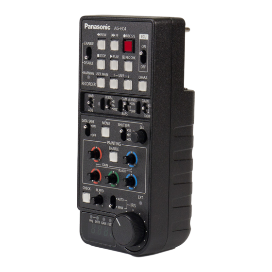
  • Seite 20: Teile Und Ihre Funktionen

    8. RECORDER ENABLE-Schalter 1. Stromschalter Dies ermöglicht, dass die Hauptstromzufuhr ON/OFF-Schalter des Aufnahmebetriebsarten 2 bis 7 durch AG-EC4G. das Gerät ausgeführt werden. 2. REC S/S Taste ENABLE: Die Betriebsarten, die durch das Gerät ausgeführt Wenn diese gedrückt wird, beginnt der werden, sind aktiviert.
  • Seite 21: Wahlschalter

    Teile und ihre Funktionen (Fortsetzung) 11. USER1-Taste BARS: Die Farbbalkensignale werden Diese führt die gleichen Funktionen aus ausgegeben. Stellen Sie unter wie die USER1-Taste am folgenden Umständen den Schalter Kamerarecorder. Der Betrieb folgt der auf diese Position: Funktion, die im Kamerarecorder Wenn der Videomonitor eingestellt zugewiesen wurde.
  • Seite 22: Weißabgleich/Automatischer Schwarzabgleich) Schalter

    Teile und ihre Funktionen (Fortsetzung) 16. W.BAL-Schalter 18. AWB/ABB LED PRST : LED leuchtet: Dies liest den voreingestellten Wert Automatischer Weißabgleich / des Weißabgleichs aus, der im automatischer Schwarzabgleich wird Kamerarecorder gespeichert wurde. durchgeführt. Wenn er auf diese Position eingestellt LED dunkel: wurde, bleibt keine Zeit mehr, den Automatischer Weißabgleich /...
  • Seite 23 Teile und ihre Funktionen (Fortsetzung) 20. MENU-Schalter 23. PAINTING GAIN-Knopf Dies öffnet die Menüanzeige am Dies ist das R/B Verstärkungsvolumen. Hauptgeräts des Kamerarecorders. Diese Taste leuchtet auf, während die 24. PAINTING ENABLE-Schalter Menüanzeige geöffnet wird. Er aktiviert den Betrieb durch die PAINTING-Verstärkung und die Menge <Hinweis>...
  • Seite 24: Anschlussbereich

    Teile und ihre Funktionen (Fortsetzung) 31. CHECK-Schalter Anschlussbereich Der Verstärkerwert, Verschlussgeschwindigkeit, Filterposition und Blendenwert werden in dieser Reihenfolge in der Nummern- LED-Anzeige angezeigt, indem dieser 1. CAM/BS-Anschluss Schalter gedrückt wird. Die Dies wird verwendet, um das Gerät mit Blendenanzeige wird wiederhergestellt, dem Kamerarecorder oder der nachdem eine vorab festgelegte Zeit Basisstation zu verbinden.
  • Seite 25: Rückseite

    Teile und ihre Funktionen (Fortsetzung) Rückseite 1. Einstellungsknopf der Frequenzcharakteristik Dieser wird verwendet, um die Frequenzcharakteristik der Videosignalausgabe vom VIDEO OUT- Anschluss einzustellen. 2. Niveaueinstellungsknopf Dieser wird verwendet, um das Niveau der Videosignalausgabe vom VIDEO OUT-Anschluss einzustellen. CAM/BS VIDEO OUT <Hinweis>...
  • Seite 26: Spezifikationen

    Spezifikationen Stromanforderungen: DC 12 V (11 V - 17 V) Stromverbrauch: 2,5 W ist die Sicherheitsinformation. [Allgemein] Erlaubte Umgebungstemperatur: 0 °C bis 40 °C Lagertemperatur: -20 °C bis 60 °C Erlaubte relative Feuchtigkeit: 10 % bis 85 % (relative Luftfeuchtigkeit) Abmessungen (B a H a T): 82 mm a 56 mm a 180 mm (außer Knöpfe)
  • Seite 27 Benutzerinformationen zur Entsorgung von elektrischen und elektronischen Geräten (private Haushalte) Dieses Symbol auf Produkten und/oder begleitenden Dokumenten bedeutet, dass verbrauchte elektrische und elektronische Produkte nicht mit gewöhnlichem Haushaltsabfall vermischt werden sollen. Bringen Sie zur ordnungsgemäßen Behandlung, Rückgewinnung und Recycling diese Produkte zu den entsprechenden Sammelstellen, wo sie ohne Gebühren entgegengenommen werden.
  • Seite 28: Lire Ces Informations En Premier

    FRANÇAIS Lire ces informations en premier ! AVERTISSEMENT: Pour réduire tout risque d’incendie ou de choc électrique, évitez d’exposer cet appareil à la pluie ou à l’humidité. Pour réduire tout risque d’incendie ou de choc électrique, éloignez l’appareil des liquides. Utiliser et ranger uniquement dans un endroit ne risquant pas de recevoir des gouttes ou d’être aspergé...
  • Seite 29 Lire ces informations en premier ! (suite) NOTE D’INFORMATION SUR LA CEM POUR L’ACHETEUR/ UTILISATEUR DE L’APPAREIL 1. Normes applicables et environnement de fonctionnement (Pour l’Europe) L’appareil est conforme: aux normes EN55103-1 et EN55103-2 1996.11, et aux environnements électromagnétiques E1, E2, E3 et E4 2.
  • Seite 30 Nous vous remercions d’avoir acheté cette Unité de commande AG-EC4G (à laquelle il sera fait référence par la suite dans ces instructions avec le terme "l’unité"). L’unité est une unité de commande à distance utilisée pour commander à distance les fonctions caméra, enregistrement et lecture en la connectant à...
  • Seite 31: Caractéristiques

    Caractéristiques Cette unite est une telecommande pour Une fonction d’affichage numérique à 4 les enregistreurs a carte memoire et les chiffres est appliquée de manière à ce que camescopes DVCPRO. la vitesse de l’obturateur puisse être Des boutons spéciaux correspondant au confirmée même pendant le balayage par bouton UTILISATEUR PRINCIPAL, bouton synchronisation.
  • Seite 32: Précautions Lors De La Connexion Du Système

    Précautions lors de la connexion du système Faites attention aux points suivants lors de la connexion de l’unité avec un caméscope ou une station de base (AG-BS300E, en option): Utilisez le câble spécial joint. Utilisez le cable en option (AJ-C10050G, en option) lors de la prolongation de la longueur.
  • Seite 33: Connexions Du Système

    AUTO IRIS deg SHTR GAIN FILTER Moniteur AG-EC4G <Remarques> La vidéo n’est pas transmise à partir du connecteur de SORTIE VIDEO de l’unité lorsqu’il est connecté à la station de base, et le mode système est réglé sur 1080/23.98PsF, 1080/24PsF, 1080/60i ou 720/60p.
  • Seite 34: Pièces Et Leurs Fonctions

    8. Commutateur d’RECORDER ENABLE Celui-ci permet d’effectuer les opérations 1. Commutateur d’alimentation d’enregistrement de 2 à 7 sur l’unité. Commutateur d’alimentation principal ON/OFF de l’AG-EC4G. ENABLE: Les opérations effectuées par l’unité sont activées. 2. Bouton REC S/S DESABLE: Les opérations effectuées Lorsqu’on appuie sur celui-ci, le...
  • Seite 35 Pièces et leurs fonctions (Suite) 11. Bouton USER1 BARS: Des signaux de mire de couleur sont Celui-ci a la même fonction que le transmis. Réglez le commutateur sur bouton USER1 du caméscope. Le cette position dans les circonstances fonctionnement suivra la fonction qui a suivantes: été...
  • Seite 36 Pièces et leurs fonctions (Suite) 16. Commutateur W.BAL 18. LED AWB/ABB PRST : LED allumée: Celui-ci sert à lire la valeur préréglée Réglage automatique de l’équilibre de l’équilibre des blancs mémorisée des blancs / réglage automatique de dans le caméscope. l’équilibre des noirs en cours Réglez-le sur cette position si vous LED sombre:...
  • Seite 37 Pièces et leurs fonctions (Suite) 20. Commutateur MENU 24. Commutateur PAINTING ENABLE Cela ouvrira l’affichage du menu de Il permet le fonctionnement par le gain l’unité principale du caméscope. Ce de PAINTING et de volume noir. bouton s’allumera à l’ouverture de 25.
  • Seite 38: Zone Des Connecteurs

    Pièces et leurs fonctions (Suite) 31. Commutateur de vérification Zone des connecteurs (CHECK) La valeur du gain, la vitesse de l’obturateur, la position du filtre et la valeur du diaphragme s’affichent dans cet ordre sur la LED d’affichage de 1. Connecteur CAM/BS numéro en appuyant sur ce Celui est utilisé...
  • Seite 39: Côté Arrière

    Pièces et leurs fonctions (Suite) Côté arrière 1. Bouton d’ajustement des caractéristiques de fréquence Celui-ci est utilisé pour ajuster les caractéristiques de fréquence de la sortie du signal vidéo provenant du connecteur de SORTIE VIDEO. 2. Bouton d’ajustement de niveau Celui-ci est utilisé...
  • Seite 40: Spécifications

    Spécifications Puissance requise: CC 12 V (11 V - 17 V) Consommation: 2,5 W Informations concernant la sécurité. [Générales] Température ambiante admise: 0 °C à 40 °C (32 °F à 104 °F) Temperature de stockage: -20 °C à 60 °C (-4 °F à 140 °F) Humidité...
  • Seite 41 Informations relatives à l’évacuation des déchets, destinées aux utilisateurs d’appareils électriques et électroniques (appareils ménagers domestiques) Lorsque ce symbole figure sur les produits et/ou les documents qui les accompagnent, cela signifie que les appareils électriques et électroniques ne doivent pas être jetés avec les ordures ménagères. Pour que ces produits subissent un traitement, une récupération et un recyclage appropriés, envoyez-les dans les points de pré-collecte désignés, où...
  • Seite 42: Leggere Prima Quanto Segue

    ITALIANO Leggere prima quanto segue! AVVERTIMENTO: Per ridurre il rischio d’incendio o di folgorazione, non esporre questo prodotto alla pioggia o all’umidità. Per ridurre il rischio d’incendio o di folgorazione, mantenere questo prodotto lontano da ogni tipo di liquido. Usarlo e conservarlo soltanto in luoghi che non siano esposti a gocciolamenti o spruzzi di liquidi, e non mettervi sopra recipienti di liquidi.
  • Seite 43 Leggere prima quanto segue! (continua) AVVISO EMC PER L’ACQUIRENTE/UTENTE DELL’APPARATO 1. Standard applicabili e ambiente operativo (Per l’Europa) L’apparato è conforme a: standard EN55103-1 e EN55103-2 1996.11 e ambienti elettromagnetici delle classi E1, E2, E3 e E4. 2. Prerequisiti essenziali per la conformità agli standard sopra menzionati <1>...
  • Seite 44 Grazie per aver acquistato l’unità di controllo AG-EC4G (nel seguito delle istruzioni denominata “l’unità”). L’unità è un telecomando utilizzato per il controllo remoto delle funzioni, della registrazione e della riproduzione di una telecamera a cui viene collegato. Sommario Leggere prima quanto segue! ........I-1 Caratteristiche..............
  • Seite 45: Caratteristiche

    Caratteristiche Questa unita e un telecomando per Funzione di display numerico a 4 cifre che telecamere con memory card e consente di verificare la velocità telecamere DVCPRO. dell’otturatore anche durante Tasti dedicati corrispondenti al tasto USER sincronizzazione e scansione. MAIN, al tasto USER1 e al tasto USER2 Manopola di grosse dimensioni per delle telecamere con memory card e un’accurata messa a fuoco dell’obiettivo.
  • Seite 46: Precauzioni Per Il Collegamento Del Sistema

    Precauzioni per il collegamento del sistema Per collegare l’unità a una telecamera o a una stazione di base (AG-BS300E, opzionale), osservare le seguenti precauzioni: Utilizzare lo specifico cavo fornito. Utilizzare il cavo opzionale (AJ-C10050G, opzionale) per estendere la lunghezza. Accendere l’unità dopo aver acceso l’alimentazione della telecamera o della stazione di base.
  • Seite 47: Collegamenti Del Sistema

    AUTO IRIS deg SHTR GAIN FILTER Monitor AG-EC4G <Note> Il video non viene trasmesso dal connettore VIDEO OUTPUT dell’unità se è collegata alla stazione di base e la modalità di sistema è impostata a 1080/23.98PsF, 1080/24PsF, 1080/ 60i o 720/60p.
  • Seite 48: Parti E Funzioni

    ENABLE: Le operazioni eseguite 1. Interruttore dall’unità sono abilitate. Interruttore ON/OFF di alimentazione DESABLE: Le operazioni eseguite principale dell’AG-EC4G. dall’unità sono disabilitate. 2. Tasto REC S/S 9. Indicatore di WARNING Alla pressione di questo tasto, la Indica che si e verificato un errore nella telecamera inizia la registrazione;...
  • Seite 49 Parti e funzioni (continua) 12. Tasto USER2 CAM.AUTO KNEE ON: Vengono trasmesse le immagini Ha la stessa funzione del tasto USER2 della telecamera. La funzione eseguita è riprese dalla telecamera. Il circuito AUTO KNEE è abilitato. È anche quella assegnata al tasto della possibile assegnare la funzione telecamera.
  • Seite 50 Parti e funzioni (continua) 19. Interruttore DATA SAVE Per ulteriori dettagli, vedere le rispettive pagine delle istruzioni operative della Questo interruttore seleziona se telecamera utilizzata. memorizzare sulla telecamera le impostazioni effettuate dall’unità. 17. Interruttore AWB/ABB ON: Le impostazioni effettuate (bilanciamento automatico del dall’unità...
  • Seite 51 Parti e funzioni (continua) 21. Interruttore SHUTTER 26. Interruttore AUTO IRIS Utilizzato per regolare il funzionamento Interruttore AUTO IRIS ON/OFF dell’otturatore. <Nota> Impostare il selettore MANUAL/AUTO OFF: Disattiva il funzionamento dell’obiettivo su AUTO. dell’otturatore. FIX: Attiva la modalità di 27. Manopola IRIS funzionamento fisso Se 26.
  • Seite 52: Area Connettori

    Parti e funzioni (continua) 32. Indicatore FILTER Area connettori Questa spia si illumina quando sul 30. LED del display numerico viene mostrata la posizione del filtro. 33. Indicatore GAIN 1. Connettore CAM/BS Questa spia si illumina quando sul 30. Utilizzato per collegare l’unità alla LED del display numerico viene mostrato telecamera o alla stazione di base.
  • Seite 53: Lato Posteriore

    Parti e funzioni (continua) Lato posteriore 1. Manopola di regolazione della caratteristica di frequenza Utilizzata per regolare le caratteristiche di frequenza del segnale video trasmesso dal connettore VIDEO OUT. 2. Manopola di regolazione del livello Utilizzata per regolare il livello del segnale video trasmesso dal connettore VIDEO OUT.
  • Seite 54: Specifiche Tecniche

    Specifiche tecniche Requisiti di alimentazione: DC 12 V (11 V - 17 V) Consumo energetico: 2,5 W sono le informazioni sulla sicurezza. [Generale] Temperatura ambiente consentita: Da 0 °C a 40 °C Temperatura di immagazzinaggio: Da -20 °C a 60 °C Umidità...
  • Seite 55 Informazioni per gli utenti sullo smaltimento di apparecchiature elettriche ed elettroniche obsolete (per i nuclei familiari privati) Questo simbolo sui prodotti e/o sulla documentazione di accompagnamento significa che i prodotti elettrici ed elettronici usati non devono essere mescolati con i rifiuti domestici generici. Per un corretto trattamento, recupero e riciclaggio, portare questi prodotti ai punti di raccolta designati, dove verranno accettati gratuitamente.
  • Seite 56: Lea Esto Primero

    ESPAÑOL Lea esto primero ADVERTENCIA: Para reducir el riesgo de producir un incendio o recibir una sacudida eléctrica, no exponga este equipo a la lluvia ni a la humedad. Para reducir el riesgo de incendio o sacudida eléctrica, mantenga este equipo alejado de todos los líquidos.
  • Seite 57 Lea esto primero (continuación) AVISO SOBRE CEM PARA EL COMPRADOR/USUARIO DEL APARATO 1. Normas aplicables y ambiente de funcionamiento (Para Europa) El aparato está conforme con: normas EN55103-1 y EN55103-2 1996.11. y ambientes electromagnéticos E1, E2, E3 y E4. 2. Condiciones previas para conseguir la conformidad con las normas mencionadas <1>...
  • Seite 58 Gracias por haber adquirido esta unidad de control AG-EC4G (a la que en adelante se denominará en estas instrucciones "la unidad"). La unidad es una unidad de control remoto que se utiliza para controlar a distancia las funciones de la videocámara, la grabación y la reproducción cuando se conecta a una videocámara grabadora.
  • Seite 59: Características

    Características Esta unidad es un control remoto para Incluye una función de visualización grabadoras de tarjetas de memoria y numérica de 4 dígitos de modo que la videocamaras grabadoras DVCPRO. velocidad del obturador se pueda La unidad incorpora botones dedicados confirmar incluso durante el barrido que corresponden a los botones USER sincronizado.
  • Seite 60: Precauciones A La Hora De Conectar El Sistema

    Precauciones a la hora de conectar el sistema Tenga cuidado con los siguientes aspectos al conectar la unidad con una videocámara grabadora o estación base (AG-BS300E, opcional): Utilice el cable dedicado incluido. Utilice el cable opcional (AJ-C10050G, opcional) cuando desee aumentar la longitud.
  • Seite 61: Conexiones Del Sistema

    AUTO IRIS deg SHTR GAIN FILTER Monitor AG-EC4G <Notas> El vídeo no se envía desde el conector VIDEO OUTPUT de la unidad cuando está conectada a la estación base y el modo del sistema se ajusta en 1080/23,98PsF, 1080/ 24PsF, 1080/60i o 720/60p.
  • Seite 62: Partes Y Sus Funciones

    Este botón permite realizar las operaciones 2 a 7 de la grabadora en la 1. Interruptor de alimentación unidad. Interruptor ON/OFF de alimentación principal de la AG-EC4G. ENABLE: Se activan las operaciones realizadas por la unidad. 2. Botón REC S/S DESABLE: Se desactivan las operaciones realizadas por la Al pulsar este botón, la videocámara...
  • Seite 63 Partes y sus funciones (Continuación) 11. Botón USER1 15. Interruptor selector OUTPUT/ Este botón realiza la misma función que AUTO KNEE el botón USER1 de la videocámara Este interruptor selecciona las señales grabadora. La operación realizará la de vídeo que se dirigen de la zona de la misma función que se asignó...
  • Seite 64 Partes y sus funciones (Continuación) 16. Interruptor W.BAL 18. LED AWB/ABB PRST : LED iluminado: En esta posición se lee el valor Balance de blancos automático / predeterminado de balance de blancos balance de negros automático en guardado en la videocámara grabadora. curso.
  • Seite 65 Partes y sus funciones (Continuación) 20. Interruptor MENU 24. Interruptor PAINTING ENABLE Este interruptor abrirá la visualización Activa el accionamiento mediante el del menú de la unidad principal de la volumen de ganancia y negro PAINTING. videocámara grabadora. Este botón se 25.
  • Seite 66: Zona De Conectores

    Partes y sus funciones (Continuación) 32. Indicador FILTER Zona de conectores Se ilumina cuando la posición del filtro se muestra en el 30. LED numérico. 33. Indicador GAIN Se ilumina cuando el valor de ganancia 1. Conector CAM/BS se muestra en el 30. LED numérico. Se utiliza para conectar la unidad con la videocámara grabadora o la estación 34.
  • Seite 67: Lado Trasero

    Partes y sus funciones (Continuación) Lado trasero 1. Mando de ajuste de las características de frecuencia Se utiliza para ajustar las características de frecuencia de la señal de vídeo enviada desde el conector VIDEO OUT. 2. Mando de ajuste del nivel Se utiliza para ajustar el nivel de la señal de vídeo enviada desde el conector VIDEO OUT.
  • Seite 68: Especificaciones

    Especificaciones Requisitos de alimentación: 12 V CC (11 V - 17 V) Consumo de energía: 2,5 W indica información de seguridad. [Generales] Temperatura ambiente admisible: de 0 °C a 40 °C (de 32 °F a 104 °F) Temperatura de almacenamiento: de -20 °C a 60 °C (de -4 °F a 140 °F) Humedad relativa admisible: de 10 % a 85 % (humedad relativa)
  • Seite 69 Información sobre la eliminación para los usuarios de equipos eléctricos y electrónicos usados (particulares) La aparición de este símbolo en un producto y/o en la documentación adjunta indica que los productos eléctricos y electrónicos usados no deben mezclarse con la basura doméstica general. Para que estos productos se sometan a un proceso adecuado de tratamiento, recuperación y reciclaje, llévelos a los puntos de recogida designados, donde los admitirán sin coste alguno.
  • Seite 70 このたびはエクステンションコントロールユニット AG-EC4G (以下、本機)をお買いあげい ただき、まことにありがとうございました。 本機はカメラレコーダーと接続して、カメラ機能および記録・再生を遠隔操作することがで きるコントロールユニットです。 目 次 安全上のご注意 ..............J-2 特 長 ................J-4 付属品 ................J-4 システム接続時の注意点 ..........J-4 システム接続 ..............J-5 各部の名称と機能 ............J-6 操作パネル部 ................J-6 コネクター部 ................J-9 背面部 ..................J-10 VIDEO OUT 出力へのメニュー表示 ......... J-10 保証とアフターサービス ..........J-11...
  • Seite 71: 安全上のご注意

    安全上のご注意 必ずお守りください ■ 誤った使い方をしたときに生じる危害や損害の程度を区分して、説明し ています。 警告 「死亡や重傷を負うおそれがある内容」です。 「傷害を負うことや、財産の損害が発生するおそれがある内容」 注意 です。 ■ お守りいただく内容の種類を、次の絵表示で区分し、説明しています。 このような絵表示は、してはいけない「禁止」内容です。 このような絵表示は、必ず実行していただく「強制」内容です。 警告 異常、 故障時には直ちに使用を中止する _ 異常があったときは、 接続プラグを外す [内部に金属や水などの液体、 異物が入ったとき、 落下などで外装ケース が破損したとき、 煙や異臭、 異音などが出たとき] (そのまま使うと、 火災の原因になります。 ) ⇒ 販売店に相談してください。 日 本 語...
  • Seite 72 警告 (続き) _ 本機がぬれたり、 水などの液体や異物が入らないようにする (火災の原因になります。 ) ⇒ 雨天 ・ 降雪 ・ 海岸 ・ 水辺での使用は、 特にご注意ください。 ⇒ 機器の上や近くに、 水などの液体が入った花びんなどの容器を置かないでください。 _ コードのプラグは、 根元まで確実に差し込む (差し込みが不完全ですと、 発熱による火災の原因になります。 ) ⇒ 傷んだプラグは使用しないでください。 _ コードが破損するようなことはしない [傷つける、 加工する、 高温部や熱機器具に近づける、 無理に曲げる、 ねじ る、 引っ張る、 重いものを載せる、 束ねるなど] (傷んだまま使用すると、 火災 ・ ショートの原因になります。 ) ⇒...
  • Seite 73: 特 長

    特 長 本機はメモリーカードレコーダー、およ シンクロスキャン時にもシャッター速度 び DVCPRO カメラレコーダーのリモコン を確認できるよう、 4 桁の数字表示機能を ユニットです。 設けました。 メモリーカードカメラレコーダー、およ レンズ絞り調整を微細に行なえるよう、 び一部の DVCPRO HD カメラレコーダー 大型のボリュームツマミを設けました。 が備えている USER MAIN ボタン、 RGB 各チャンネルのペデスタルが調整で USER1 ボタン、 USER2 ボタンにそれぞ きます。 オプションケーブル( AJ-C10050G ・別 れ対応する専用ボタンを設けました。 ただし AG-HPX555 、および AG-HPX305 売品)を使用すれば最大 50 m までの延長 接続時は...
  • Seite 74: システム接続

    SEL. VIDEO IN PAINTING ENABLE コネクターへ GAIN BLACK BNC ケーブル CHECK M.PED AUTO IRIS deg SHTR GAIN FILTER AG-EC4G モニター <ノート> ベースステーションと接続した場合、システムモードが 1080/23.98PsF 、 1080/24PsF 、 1080/60i 、もしくは 720/60p 時には、本機の VIDEO OUT 端子から映像は出力されません。 本機とベースステーション、カメラアダプター( AG-CA300G ・別売品)と組み合わせて 使用する場合、付属の 10 ピンケーブルを使用して、本機をカメラレコーダーに直接接続す ることはできません。...
  • Seite 75: 各部の名称と機能

    各部の名称と機能 5. REC CHK ボタン 操作パネル部 記録の一時停止中に押すと記録された内 容( 2 秒間のレックレビュー)の確認が できます。 DVCPRO HD カメラレコーダーの場合、 REC S/S   再生の一時停止中に押すと、つなぎ取り ENABLE するための頭出しの動作を行います。  STOP PLAY REC CHK DISABLE 6. PLAY (再生)ボタン WARNING USER MAIN CHARA USER カメラレコーダーのビューファインダー RECORDER 上、またはカラービデオモニターを使っ W.BAL A.KNEE GAIN PRST て再生画像を見るとき押します。再生中...
  • Seite 76 各部の名称と機能 (続き) 13. CHARA ボタン 16. W.BAL スイッチ 本機の VIDEO OUT 端子から出力される PRST : ビデオ信号に重畳されるキャラクターの カメラレコーダー本体に記録されて ON/OFF を制御するボタンです。 いるホワイトバランスのプリセット 値を読み出します。 <ノート> ホワイトバランスを調整する時間が ベースステーションに接続時、カメラレ ないときなどにこの位置にします。 コーダー本体の REMOTE 端子から出力 A または B : されるビデオ信号に対してのみ、このボ カメラレコーダー本体のホワイトバ タンは有効になります。 ランス A または B にメモリーされて いる値を読み出します。 14.
  • Seite 77 各部の名称と機能 (続き) 19. DATA SAVE スイッチ シャッタースピードの切り替えはメ ニューを非表示に設定時( 20.MENU ス 本機での設定内容を、カメラレコーダー イッチが OFF のとき) 、 22.SEL ダイア 本体に記憶させるかさせないかの選択を ルを使用して行います。シャッタース 行なうスイッチです。 ピードの数値は 30. 数値表示 LED に表示 本機での設定内容を、カメラレ されます。 コーダー本体に記憶させます。 <ノート> 記憶させる内容については、各 本機の SHUTTER スイッチが ON の状態 カメラレコーダーの取扱説明書 で、カメラレコーダー側で DS.GAIN 機 を参照してください。 能を動作させた場合、...
  • Seite 78: コネクター部

    各部の名称と機能 (続き) 28. EXT INDICATOR コネクター部 レンズエクステンダー使用時に点灯しま す。 29. M.PED つまみ マスターペデスタルの設定を行います。 1. CAM/BS 端子 30. 数値表示 LED 本機とカメラレコーダー、またはベース アイリス値、ゲイン、シャッタースピー ステーションとの接続端子です。 ド、フィルターポジションを表示しま す。通常はアイリスを表示しています ピン No. 信号内容 が、ゲイン 、シャッタースピード、 CAM DATA (H) フィルターポジション変更時、各数値を CAM DATA (C) 9 10 表示します。 CAM CONT (H) 31.
  • Seite 79: 背面部

    各部の名称と機能 (続き) 1. 周波数特性調整つまみ 背面部 VIDEO OUT 端子から出力されるビデオ 信号の周波数特性を調整するのに使用し ます。 2. レベル調整つまみ VIDEO OUT 端子から出力されるビデオ 信号のレベルを調整します。 <ノート> 上記のつまみで調整を行う場合、背面のカ バーを外し、刃幅 2.5 mm 程度のマイナス調 CAM/BS VIDEO OUT 整ドライバーなどを差し込んで行ってくだ さい。 VIDEO OUT 出力へのメニュー表示 本機をカメラレコーダーの REMOTE コネクターに接続時: MENU スイッチを ON にし、 CHARA ボタンを ON にすると、 VIDEO OUT 端子から出力され る映像に設定メニューが表示されます。...
  • Seite 80: 保証とアフターサービス

    保証期間:お買い上げ日から本体 1 年間 容は、お買い上げの販売店にご相談くだ さい。 8 年 補修用性能部品の保有期間 当社では、エクステンションコントロー ルユニットの補修用性能部品を、製造打 ち切り後、 8 年保有しています。 ※補修用性能部品とは、その製品の機能 を維持するために必要な部品です。 修理を依頼されるとき この取扱説明書を再度ご確認の上、お買い上 ご連絡いただきたい内容 げの販売店までご連絡ください。 エクステンションコントロール 品 名 ユニット ◆ 保証期間中の修理は. . . AG-EC4G 品 番 保証書の記載内容に従って、修理させて 製造番号 いただきます。詳しくは、保証書をご覧 お買い上げ日 ください。 故障の状況 ◆ 保証期間経過後の修理は. . . 修理により、機能、性能の回復が可能な 場合は、ご希望により有料で修理させて いただきます。 J-11...
  • Seite 81: 定 格

    定 格 [ 入出力部 ] 電 源 : DC 12 V (11 V ∼ 17 V) 消費電力: 2.5 W CAM/BS : 丸型 10 ピン は安全項目です。 [ 出力部 ] [ 総合 ] VIDEO : 動作周囲温度: VBS 、 1 V [P-P] 、 75 h 0 ℃∼ 40 ℃ 保存温度:...
  • Seite 82 Panasonic Broadcast & Television Systems Company Unit Company of Panasonic Corporation of North America Executive Office: One Panasonic Way 4E-7, Secaucus, NJ 07094 Tel: 201-348-7000 Eastern Zone: One Panasonic Way 4E-7, Secaucus, NJ 07094 Tel: 201-348-7196 Southeast Region: Tel: 201-392-6151 Western Zone: 3330 Cahuenga Blvd W., Los Angeles, CA 90068 Tel: 323-436-3608...

Inhaltsverzeichnis