Werbung
Quicklinks
0. Einführung
0. Introduction
DE
Der Induktive Feinzeiger Millimess 2100 ist ein vielseitiges
The Inductive Dial Comparator Millimess 2100 is a versatile
Präzisionsmessgerät für den wirtschaftlichen Einsatz in der
precision measuring instrument for economic application on
Fertigung und im Messraum.
the production line and in the inspection room.
Lesen Sie die Bedienungsanleitung sorgfältig durch, um das
Please read these operating instructions carefully to ensure
Messgerät in vollem Umfang nützen zu können.
optimal usage of this measuring instrument.
Änderungen sowohl am Messgerät als auch am Inhalt dieser
We reserve the right to make modifications to the measuring
Bedienungsanleitung behalten wir uns vor.
instrument as well as to the contents of these instructions.
Lieferumfang
Standard accessories
• Inductive Dial Comparator
• Induktiver Feinzeiger
• mains adapter
• Steckernetzteil
• rubber bellow
• Gummibalg
• spanner for preliminary stroke setting
• Schlüssel für Vorhubeinstellung
• inspection certificate
• Abnahmeprotokoll
• plastic case
• Kunststoffetui
Warnhinweis: Achten Sie darauf, dass nur das Original-
Warning: Please use only the provided original mains adapter.
Steckernetzteil verwendet wird.
Hinweise
Important information
Bitte beachten Sie die folgenden Hinweise um Beschädigun-
Please note the following to prevent damage and/or malfunc-
gen bzw. Fehlfunktionen des Messgeräts auszuschließen:
tion of the measuring instrument:
• Beachten Sie die Lager- und Arbeitstemperatur des Geräts
• Please observe the storage and working temperature of this
(siehe technische Daten).
instrument (see Technical data).
• Do not subject the instrument to an electrical voltage (i.e.
• Setzen Sie das Messgerät keiner elektrischen Spannung
from an electric marking unit, etc.).
(z.B. durch elektrisches Signiergerät, etc.) aus.
• Do not damage and/or modify the instrument.
• Beschädigen bzw. modifizieren Sie das Gerät nicht.
• Keep the data ouput as well as the socket for the charger
• Datenausgang bzw. Netzteilanschluss verschließen, wenn
lead covered when these are not in use.
diese nicht benützt werden.
• This instrument is splash water-proof when using the
• Das Messgerät ist bei Verwendung des Gummibalgs zur
rubber bellows for sealing the measuring spindle guide
Abdichtung der Messbolzenführung spritzwassergeschützt
(IP 54 acc. IEC 60529).
(IP 54 nach IEC 60529).
• The measuring instrument has to be used in a mounting
• Das Messgerät ist in einer Messuhrhalterung oder entspre-
device or other suitable fixture. We recommend a device with
chenden Vorrichtung zu betreiben. Empfohlen wird eine mit
a split mounting bore of dia. 8 H7 mm.
einem Schlitz versehene Halterung mit Aufnahmebohrung
• For cleaning of the front cover/dial glass use a soft cloth
8 H7 mm.
moistened with a neutral reacting cleaning agent. Never use
• Säubern Sie die Frontabdeckung / Klarsichtscheibe mit
organic solvents like thinners and petrol. For cleaning of the
einem weichen mit neutralem Reinigungsmittel ange-
measuring spindle use a cloth moistened with alcohol. Do
feuchteten Tuch. Verwenden Sie niemals organische
not apply oil on to the measuring spindle!
Lösungsmittel wie Verdünnung und Benzin. Reinigen Sie den
Messbolzen mit einem in Alkohol angefeuchteten Tuch. Kein
Öl auf dem Messbolzen aufbringen!
EG-Konformitätserklärung
EC Declaration of Conformity
Dieses Messgerät entspricht der Niederspannungsrichtlinie
This measuring instrument conforms to the Low Voltage
2006/95/EG und der Richtlinie über die elektromagnetische
Directive 2006/95/EG and the Directive 2004/108/EG which
Verträglichkeit 2004/108/EG.
concerns Electromagnetic compatibility.
Old electronic equipment of the type Millimess 2100 which
Elektrische Altgeräte der Type Millimess 2100, die nach
dem 23. März 2006 durch Mahr in den Verkehr gebracht
where brought from Mahr after the 23. March 2006 can
werden, können an uns zurückgegeben werden. Wir füh-
be returned to us for disposal. We will dispose/recycle
ren diese Geräte einer umweltgerechten Entsorgung zu.
our products without causing any harm or damage to the
Die EU-Richtlinien 2002/95/EG RoHS und 2002/96/EG
environment in accordance to the EU-Directives 2002/95/
EC RoHS (the Restriction of the use of certain Hazardous
WEEE bzw. das ElektroG finden dabei ihre Anwendung.
Substances) and 2002/96/EC WEEE (Waste Electrical and
Electronic Equipment) as well as German National - Electri-
cal and Electronic Equipment Act, FRG.
1. Techn. Daten, Lieferumfang und Bezeichnungen
1. Technical data, standard accessories and
designations
Technische Daten
Technical Data
Mess-
Ziffernschritt
Anzeige-
Fehlergrenze*
Meas.
bereiche
umschaltbar
bereich der
range
umschaltbar Skalenanzeige
innerhalb
switchable
mm
(inch)
mm/inch
mm (inch)
±0,8mm 1,4mm
mm
(inch)
±1,0 (.04") 0,0005/.00002" ± 0,015 (.0006")
±1,0 (.04") 0,0005/.00002" ± 0,015 (.0006")
0,001/.00005" ± 0,030 (.0015") 1µm
2µm
±1,4 (.55")
±1,4 (.55")
0,005/.0002" ± 0,150 (.0060")
0,01/.0005"
± 0,300 (.0150")
* + 1 resolution
* + 1 Ziffernschritt
Free stroke
Freihub
nach oben 1,8 mm
Total stroke
Gesamthub
4,6 mm
Measuring force
Messkraft
0,7-0,9 N (mit Standardfeder)
Measuring system
Messsystem
induktiv
Display
Anzeige
LCD, Ziffernhöhe 6,5 mm mit grüner
bzw. roter Hintergrundbeleuchtung
Class of protection
Schutzart
IP 54 nach IEC 529 bei Einsatz mit
Gummibalg
Operating temperature
Betriebstemperatur
+5° C bis +40° C
Storage temperature
Lagertemperatur
–10° C bis +60° C
Data output
Datenausgang
RS232C kompatibel über Interface-
kabel mit Optokoppler, USB oder
Digimatic
Weight
Gewicht
170 g
Order no.
Bestell-Nr.
4346200 (230 V), 4346201 (120 V)
Bezeichnungen
Designations
1 Bedientasten
9 Gummibalg
1 Operating keys
2 Anzeige
10 Abdeckschraube
2 Display
3 Einspannschaft
11 Steckernetzteil
3 Mounting shank
4 Messbolzen
12 Einstellschlüssel für
4 Measuring spindle
5 Messeinsatz
Vorhub
5 Contact point
6 Anschluss für
13 Vorhubeinstellschraube
6 Socket for mains adapter
Steckernetzteil
14 Befestigungsöse 1085 b
7 Data output / Control
7 Datenausgang /
(Best.-Nr. 4336310)
output
Steuerausgang
15 Adapterbüchse 940
8 Swivelling operating and
8 Drehbares Bedien- und
(Best.-Nr. 4310103)
display unit
Anzeigeteil
6
10
7
1
8
TOL
MAX/MIN
RANGE
ON/OFF
SET TOL
mm/inch
0
30
0.00
30
I
mm
ABS
PRESET
DATA
0
RESET
2
SET
ABS
Millimess 2100
13
3
12
9
4
4 4
5
2. Vorbereiten des induktiven Feinzeigers
EN
2.1 Spannungsversorgung
– Steckernetzteil (11) an das Wechselspannungsnetz
(230/120 V) und das Kabel an die Buchse (6) anschließen.
2.2 Einstellen des drehbaren Anzeige- und Bedienteils
Gehäuseoberteil ist von +90° bis -180° drehbar (2.2).
Achtung: Wird das Display über die Anschlagpunkte A ge-
dreht kann dies zur Beschädigung des Messgeräts führen!
2.3 Anbringen von Abhebeeinrichtungen
2.3a) Abhebung mit Drahtabheber (Zubehör 4346010)
– Abdeckschraube (10) mit Münze entfernen
– Handabhebung (2.3a) in das Gehäuse einschrauben
– Messbolzen in das Gehäuse eindrücken, bis ein deutliches
Klicken zu hören ist
– Ggf. Drahtabheber in die Handabhebung einschrauben.
– Ausbau erfolgt in umgekehrter Reihenfolge.
2.3b) Pneumatische Abhebung (Zubehör 4346011)
– Abdeckschraube (10) mit Münze entfernen
– Abhebung (2.3b) in das Gehäuse einschrauben
– Messbolzen in das Gehäuse eindrücken, bis ein deutliches
Klicken zu hören ist.
– Ausbau erfolgt in umgekehrter Reihenfolge.
Hinweis: Für die Abhebung ist ein Überdruck von 5 bis 8 bar
erforderlich. Zudem muss die Luft ölfrei und gefiltert sein.
2.4 Anbringen der Messkrafteinstellung (Zubehör 4346012)
– Abdeckschraube (10) mit Münze entfernen
– Messkrafteinstellschraube in Gehäuse einschrauben bis
schwarzer Dichtring nicht mehr sichtbar ist (halbe Mess-
kraft). Durch weiteres Einschrauben wird die Messkraft
erhöht.
Hinweis: Messkraft ist von verwendeter Feder abhängig.
2.5 Austausch der Messkraftfeder
– Abdeckschraube (10) mit Münze entfernen
– Messkraftfeder entfernen und gegen gewählte ersetzen.
Hinweis: Es sind Messkraftfedern zwischen 0,25 N und
2,5 N erhältlich.
2.1
2.6 Befestigung des Messgeräts
Hinweis: Zur optimalen Nutzung des Messbereichs, Mess-
gerät im ABS-Modus (3.1c) betreiben und Arbeitsbereich
möglichst nahe an elektrischen Nullpunkt legen.
Messuhrhalterung
Resolution
Display range
Span of error*
Zur Aufnahme wird eine mit einem Schlitz versehene Halter-
switchable
of analog
ung mit Aufnahmebohrung 8 H7 mm empfohlen (2.6a).
display
within
Hinweis: Ist eine Aufnahmebohrung mit 3/8" (9,52 mm)
mm/inch
mm (inch)
±0,8mm 1,4mm
vorhanden, muss die Adapterbüchse 940 (4310103) verwen-
det werden.
0,001/.00005" ± 0,030 (.0015") 1µm
2µm
Wichtig! Schraube darf nicht auf den Einspannschaft drücken,
0,005/.0002" ± 0,150 (.0060")
damit freier Lauf des Messbolzens gewährleistet ist.
0,01/.0005"
± 0,300 (.0150")
Befestigungsöse 1085 b (Zubehör 4336310)
Achtung: Bevor Sie die Rückwand entfernen, muss das
Messgerät von der Spannungsversorgung getrennt werden!
upwards 1,8 mm
4,6 mm
– 4 Schrauben der Geräterückwand lösen
0,7-0,9 N (with standard spring)
– Rückwand entfernen
inductive
– Befestigungsöse anbringen (2.6b).
LCD, height of digits 6,5 mm, with a
2.7 Austausch des Messeinsatzes
green resp. red backlit display
Falls Einsatz nicht von Hand lösbar,
IP 54 acc. IEC 529 when used
– Messbolzen mit Zange festhalten. Zum Schutz der Messbol-
with rubber bellows
zenoberfläche ein Stück Stoff benützen
+5° C to +40° C
– Messeinsatz mit zweiter Zange vorsichtig entfernen.
–10° C to +60° C
Wichtig! Unvorsichtiges Handeln kann zu Schäden im Gerä-
RS232C compatible via interface-
teinneren oder am Messbolzen führen.
cable with opto-coupler;
USB or Digimatic
2.8 Einstellen des Vorhubs
170 g
– Vorhub ist mit Innensechskantschlüssel (12) im Bereich
4346200 (230 V), 4346201 (120 V)
-1,4 mm bis 0* einstellbar.
Hinweis: Einstellung des Vorhubs ist dann sinnvoll, wenn
ein Werkstück in eine Messvorrichtung eingeführt werden
soll, ohne den Messbolzen dabei manuell oder pneumatisch
abzuheben.
*bezogen auf elektrischen Nullpunkt
2.9 Aktivieren der Einschaltautomatik
Hinweis: Bei aktivierter Einschaltautomatik, schaltet der
Millimess 2100 ein, wenn Spannung anliegt. Das Messgerät
läßt sich dann nur durch Trennen der Spannungsversorgung
abschalten. Beim Betätigen der OFF-Taste erscheint LOC in
der Anzeige.
Achtung: Bevor Sie die Rückwand entfernen, muss das
Messgerät von der Spannungsversorgung getrennt werden!
– 4 Schrauben der Geräterückwand lösen
– Rückwand entfernen
– DIP-Schalter (24) auf Platine mit kleinem Schraubendreher
9 Rubber bellows
umschalten (ggf. Gehäuseoberteil verdrehen, bis DIP-
10 Cover screw
Schalter sichtbar wird)
11 Mains adapter
– Rückwand wieder mit den 4 Schrauben befestigen
12 Key for preliminary
– Zum Deaktivieren der Einschaltautomatik den DIP-Schalter
stroke setting
(24) erneut umschalten.
13 Screw for preliminary
stroke setting
14 Mounting lug 1085 b
(Order no. 4336310)
15 Adapter bush 940
(Order no. 4310103)
2.6
34,5
2.6a)
8,5
2.6b)
16,5
8,5
14
19
ø.375"
15
ø8h6
ø4
2. Preparing the Inductive Dial Indicator
DE
2.1 Power supply
– Plug the mains adapter (11) into your mains (230/120 V)
and the cable into the socket (6).
2.2 Adjusting the rotatable operating and display unit
The display can be rotated from +90° to -180° (2.2).
Attention: Turning the display past the stops A can lead to
damage of the instrument!
2.3 Mounting of the lifting devices
2.3a) Manual lift with Cable release (Accessory 4346010)
– Remove the cover screw (10) by using a coin
– screw the manual lift into the housing (2.3a)
– push the measuring spindle into the housing until a definite
click can be heard.
– In the event of a cable release being used it is necessary
to screw the cable release lead into the manual lift.
– Disassemble in reverse order.
2.3b) Pneumatic lift (Accessory 4346011)
– Remove the cover screw (10) by using a coin
– screw the pneumatic lift into the housing (2.3b)
– push the measuring spindle into the housing until a definite
click can be heard.
– Disassemble in reverse order.
Note: For lift-off a pressure of 5 to 8 bar is required. The air
must be fat free and filtered.
2.4 Attaching the device for setting the measuring force
(Accessory 4346012)
– Using a coin undo the cover screw (10).
– Screw the measuring force setting screw into the hous-
ing until the black sealing ring is no longer visible (half of
measuring force). Turning the screw further increases the
measuring force.
Note: Measuring force is dependent upon which spring
is being used.
2.5 Exchange of the measuring force spring
– Remove the cover screw (10) by using a coin
– remove the measuring force spring and exchange it for
the spring that provides the required the measuring force.
Note: Measuring force springs are available between 0,25 N
and 2,5 N.
0°
2.2
TOL
MAX/MIN
RANGE
ON/OFF
SET TOL
mm/inch
11
0
30
0.00
I
PRESET
DATA
0
RESET
SET
ABS
Millimess 2100
-180°
6
A
2.3
10
mm/inch
RANGE
ON/OFF
2.5
0
30
30
0.00
I
mm
ABS
PRESET
ABS
0
RESET
SET
Extramess 2000
TOL
MAX/MIN
RANGE
ON/OFF
SET TOL
mm/inch
0
30
30
0.00
I
mm
PRESET
DATA
0
RESET
SET
ABS
Millimess 2100
2.4
2.6 Mounting of the measuring instrument
Note: For optimum use of the measuring range adjust the
measuring instrument while in ABS-mode (3.1c) as close as
possible to the electrical zero position (middle of the measur-
ing range).
Mounting device
For mounting we recommend a device with a split mounting
bore of dia. 8 H7 mm (2.6a).
Note: Devices with a mounting bore of dia. 3/8" (9,52 mm)
require an adapter bush 940 (4310103).
Important! In order to ensure unrestricted movement of the
measuring spindle do not clamp the mounting shank directly
with a screw.
Mounting lug 1085 b (Accessory 4336310)
Attention: Before removing the rear housing please discon-
nect from mains power supply!
– Undo the 4 screws on the rear of the housing
– remove the cover lid
– screw on the mounting lug (2.6b).
2.7 Exchange of the contact point
To unscrew a tight contact point please proceed as follows:
– hold the spindle tight with a pair of pliers using a piece of
cloth to protect the measuring spindle from damage
– use a second pair of pliers to unscrew the contact point.
Important! Ignoring this advice may lead to damage of the
interior of the instrument or to the measuring spindle.
2.8 Setting of the preliminary stroke
– The preliminary stroke is set with the hexagon wrench (12)
in the range of -1,4 mm to 0*.
Note: This setting can be useful, if a workpiece is to be in-
serted into a measuring device without manually or pneumati-
cally lifting up the measuring spindle.
* based on electrical zero position
2.9 Activating the ON/OFF-Automatic
Note: By activating the ON/OFF-Automatic the Millimess 2100
will only turn on once power is supplied, by disconnecting the
power source the instrument will turn off automatically. Press-
ing the OFF-Key will only result in LOC being featured in the
display.
Attention: Before removing the rear housing please discon-
nect from mains power supply!
– Undo the 4 screws on the rear of the housing
– remove the cover lid
– Switch over the Dip-switch (24) on the circuit board with a
small screwdriver (if necessary rotate front housing until the
Dip-switch is in view)
– Re-attach rear housing with the 4 screws
– To deactivate the ON/OFF-Automatic switch back the Dip-
switch (24).
2.8
TOL
MAX/MIN
RANGE
ON/OFF
SET TOL
mm/inch
ø 8 H7
0
30
30
0.00
I
mm
ABS
PRESET
DATA
0
RESET
SET
ABS
Millimess 2100
12
2.7
2.9
24
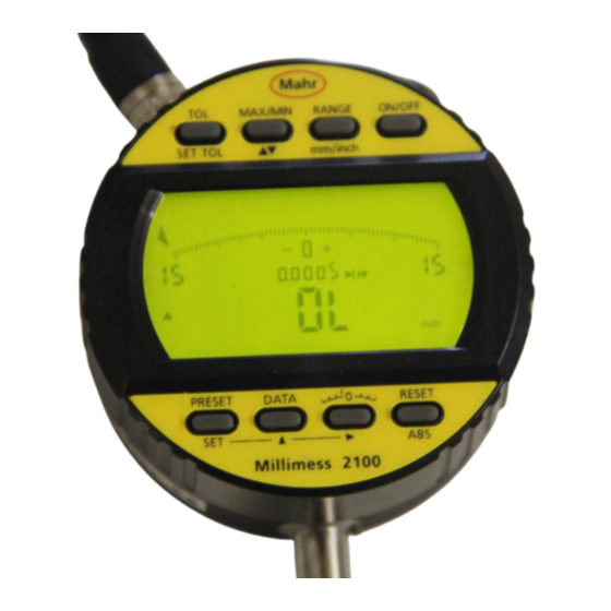
Kennzeichnung und Funktion der Bedientasten
EN
16 ON/OFF
Ein- bzw. Ausschalten des Messgerätes
17 RANGE/
Wahl des Messbereichs und der Auflösung
mm/inch
Umschaltung der Maßeinheit
18 MAX/MIN/
Maximal-/Minimalwerterfassung
Messrichtungsumschaltung
▼▲
19 TOL/
Toleranzüberwachung
SET TOL
Toleranz einstellen
20 PRESET/
Abrufen des gespeicherten Presetwerts bzw.
SET
Aktivierung des Preset-Einstellmodus (SET)
21 DATA
Angezeigten Wert über den
Datenausgang senden
22 --0--
Nullsetzen der Skalenanzeige
23 RESET/
Nullsetzen der Ziffern- und Skalenanzeige
ABS
Zeigt absolute Position des Messbolzens
bezogen auf elektrischen Nullpunkt des
Messsystems
19
20
Bedienung der Tasten
Bei kurzem Tastendruck wird die Funktion über der Taste
aktiviert, bei langem Tastendruck die Funktion unterhalb der
Taste. Ausnahme: Pfeile -▲ ,-
in der SET-Funktion.
3. Bedienung
Achtung! Höchste Genauigkeit des Messgeräts wird
erst nach einer Einschaltdauer von 10 min erreicht.
+90°
Bediendauer der Tasten
kurz (<1 Sek.)
lang (>1 Sek.)
gedrückt halten
3.1 Einstellfunktionen
30
ON / Einschalten
A
– Taste ON/OFF lang drücken
mm
=>
Das Messgerät wird eingeschaltet (in der Anzeige
erscheint kurz ON).
OFF / Ausschalten
– Taste ON/OFF kurz drücken
=>
Das Messgerät wird ausgeschaltet (in der Anzeige
erscheint kurz OFF).
Hinweis: Einstellungen (PRESET, TOL, MAX/MIN, mm/inch,
▼▲, RANGE) bleiben erhalten.
3.1a) RANGE / Messbereichsumschaltung
2.3a
– Taste RANGE kurz drücken
Ziffernschrittwert und Messbereich der Skalen- und Ziffern-
anzeige werden umgeschaltet.
Ziffernschrittwert
Messspanne
Ziffernanzeige
Skalenanzeige
mm/inch
mm (inch)
mm (inch)
0,01/.0005"
2,8 (.11")
± 0,300 (.015")
0,005/.0002"
2,8 (.11")
± 0,150 (.006")
0,001/.00005"
2,8 (.11")
± 0,030 (.0015")
0,0005/.00002"
2,0 (.08")
± 0,015 (.0006")
mm/inch / Umschaltung der Maßeinheit
– Taste mm/inch lang drücken
=>
Symbol mm erscheint in der Anzeige.
Maßeinheit mm ist aktiv.
=>
Symbol inch erscheint in der Anzeige.
2.3b
Maßeinheit inch ist aktiv.
3.1b) ▲▼ / Messrichtungsumschaltung
– Taste ▲▼ lang drücken
=>
Symbol ▲ erscheint in der Anzeige.
Positive Zählrichtung bei hineingehendem Tastbolzen
=>
Symbol ▼ erscheint in der Anzeige.
Positive Zählrichtung bei herausgehendem
Tastbolzen.
Bestätigung der Rückführbarkeit
Wir erklären in alleiniger Verantwortung, dass das Produkt
in seinen Qualitätsmerkmalen den in unseren Verkaufsunter-
lagen (Bedienungsanleitung, Prospekt, Katalog) angegebenen
Normen und technischen Daten entspricht.
Wir bestätigen, dass die bei der Prüfung dieses Produktes
verwendeten Prüfmittel, abgesichert durch unser Qualitätssi-
cherungssystem, auf nationale Normale rückführbar sind.
Wir danken Ihnen für das uns mit dem Kauf dieses Produk-
tes entgegengebrachte Vertrauen.
Änderungen an unseren Erzeugnissen, besonders aufgrund
technischer Verbesserungen und Weiterentwicklungen, müssen
wir uns vorbehalten.
Alle Abbildungen und Zahlenangaben usw. sind daher ohne
Gewähr.
© by Mahr GmbH
Confirmation of traceability
We declare under our sole responsibility that this product is
in conformity with standards and technical data as speci-
fied in our sales documents (operating instructions, leaflet,
catalogue).
We certify that the measuring equipment used to check
this product, and guaranteed by our Quality Assurance, is
traceable to national standards.
Thank you very much for your confidence in purchasing
this product.
We reserve the right to make changes to our products, especially
due to technical improvements and further developments.
All illustrations and technical data are therefore without guar-
antee.
© by Mahr GmbH
Designation and function of the operating keys
DE
EN
16 ON/OFF
Switches instrument on resp. off
17 RANGE/
Selection of measuring range and resolution
mm/inch
Selection of measuring unit
18 MAX/MIN/
Display of maximum-/minimum value
Selection of measuring direction
▼▲
19 TOL/
Monitoring of tolerance
SET TOL
Set tolerance
20 PRESET/
Call-up of the stored Preset-values resp.
SET
activation of the Preset-setting mode (SET)
21 DATA
Displayed value will be sent via the data
output
22 --0--
Zeroing of the analog display
23 RESET/
Zeroing of the digital and analog display
ABS
Shows the reference to the electrical zero of
the measuring system
18
17
16
TOL
MAX/MIN
RANGE
ON/OFF
SET TOL
mm/inch
0
30
0.00
30
I
mm
ABS
PRESET
ABS
0
RESET
SET
23
Extramess 2001
21
22
Operating the keys
With a short press of the key the function displayed above the
key will be activated, a long press will activate the function dis-
played below the key. Exception: in the SET-Function -▲ ,-
.
3. Operation
In order to obtain highest accuracy the instrument re-
quires at least a warm-up period of 10 minutes.
Duration of key activation
short (<1 sec)
long (>1 sec)
hold down
3.1 Setting functions
ON
– Long activation of ON/OFF
=>
Switches the instrument on (after a short period of
time On is shown in the display)
OFF
– Short activation of ON/OFF
=>
Switches the instrument off (the display shows for a
short period Off)
Note: Settings (PRESET, TOL, MAX/MIN, mm/inch, ▼▲,
RANGE) are retained.
3.1a) RANGE / Selection of measuring range
– Short activation of RANGE-key
Simultaneous change-over of reading and measuring range of
analog- and digital display.
Readings
Measuring span
Digital display
Analog display
mm/inch
mm (inch)
mm (inch)
0,01/.0005"
2,8 (.11")
± 0,300 (.015")
0,005/.0002"
2,8 (.11")
± 0,150 (.006")
0,001/.00005"
2,8 (.11")
± 0,030 (.0015")
0,0005/.00002"
2,0 (.08")
± 0,015 (.0006")
mm/inch / Selection of measuring unit
– Long activation of mm/inch-key
=>
Symbol mm is displayed.
mm-unit is activated
=>
Symbol inch is displayed.
inch-unit is activated
3.1b) ▲▼ / Selection of measuring direction
– Long activation of ▲▼
=>
Symbol ▲ is displayed. Values increase when the
spindle moves inwards
=>
Symbol ▼ is displayed. Values increase when the
spindle moves outwards
DE
EN
Induktiver Feinzeiger
Inductive Dial Comparator
Millimess 2100
Bedienungsanleitung
Operating Instructions
3756635
Mahr GmbH
Standort Esslingen
Reutlinger Str. 48, 73728 Esslingen,
Tel. +49 711 9312 600, Fax +49 711 9312 756
e-mail: mahr.es@mahr.de, www.mahr.com
0614
Werbung

Verwandte Anleitungen für Mahr Millimess 2100


Inhaltszusammenfassung für Mahr Millimess 2100
- Seite 1 Ein- bzw. Ausschalten des Messgerätes 16 ON/OFF Switches instrument on resp. off Der Induktive Feinzeiger Millimess 2100 ist ein vielseitiges The Inductive Dial Comparator Millimess 2100 is a versatile 2.1 Spannungsversorgung 2.1 Power supply 17 RANGE/ Wahl des Messbereichs und der Auflösung...
- Seite 2 3.1c) ABS 3.1c) ABS 3.2e) TOL/Toleranzüberwachung 3.2e) TOL/Tolerance monitoring SET: Toleranz einstellen SET Tol: Set tolerance – Taste ABS lang drücken – Short activation of ABS => Symbol ABS erscheint im Display => Symbol ABS is displayed. – Taste SET TOL lang drücken –...