KEB COMBIVERT F5 SERVO Installationsanleitung
Inhaltsverzeichnis
Verfügbare Sprachen
Verfügbare Sprachen
Quicklinks
Kapitel
Inhaltsverzeichnis

Verwandte Anleitungen für KEB COMBIVERT F5 SERVO


Inhaltszusammenfassung für KEB COMBIVERT F5 SERVO
- Seite 1 C O M B I V E R T � Installationsanleitung Gehäuse A Installation Guideline Housing A 09/2005...
- Seite 2 D - 3 ..D - 26 GB - 3 ..GB - 26...
- Seite 3 D - 3...
- Seite 4 Diese Anleitung beschreibt den KEB COMBIVERT F5. Im Einzelnen wird auf den Einbau, die Anschlussmöglichkeiten sowie die grundlegende Bedienung eingegangen. Aufgrund der vielfältigen Einsatz- und Programmiermöglichkeiten ist der anwendungsspezifische Anschluss- bzw. Verdrahtungsplan, die Parametereinstellung sowie Hinweise zur Inbetriebnahme der Dokumentation des Maschinenherstellers zu entnehmen.
-
Seite 5: Inhaltsverzeichnis
3.3.5 Anschluss der Temperaturerfassung .................. 13 3.3.6 Anschluss eines Bremswiderstandes mit Temperaturüberwachung gemäß UL ....14 Geberinterfaceanschluss ..................14 3.4.1 Resolveranschluss bei KEB Motoren über Buchse X3A ............ 14 3.4.2 Inkrementalgebereingang / -nachbildung X3B ..............15 Steuerkarte .......................16 3.5.1 Steuerklemmleiste X2A ...................... 16 3.5.2 Anschluss der Steuerklemmleiste .................. -
Seite 6: Wichtig, Unbedingt Lesen
Wichtig, unbedingt lesen Sicherheits- und Anwendunghinweise Sicherheits- und Anwendungshinweise für Antriebsstromrichter (gemäß: Niederspannungsrichtlinie 73/23/EWG) 1. Allgemein schützen. Insbesondere dürfen bei Transport und Handhabung keine Bauelemente verbogen und/oder Isolationsabstände Während des Betriebes können Antriebsstromrichter ihrer verändert werden. Die Berührung elektronischer Bauelemente Schutzart entsprechend spannungsführende, blanke, und Kontakte ist zu vermeiden. -
Seite 7: Produktbeschreibung
Regelung von Sychron-Servomotoren. Der Betrieb anderer elektrischer Verbraucher ist untersagt und kann zur Zerstörung der Geräte führen. Die Steller sind bei Auslieferung auf die von KEB gelieferten Servomotoren abgestimmt. Servosteller sind Komponenten, die zum Einbau in elektrische Anlagen oder Maschinen bestimmt sind. -
Seite 8: Technische Daten
Produktbeschreibung Technische Daten Servogröße Gehäusegröße Phasen Eingangsbemessungsspannung Ausgangsbemessungsleistung [kVA] Ausgangsbemessungsstrom Stillstandsdauerstrom Max. Kurzzeitgrenzstrom OC-Auslösestrom Eingangsbemessungsstrom [A] 4,6 Bemessungsschaltfrequenz [kHz] Max. Schaltfrequenz [kHz] Verlustleistung bei Bemessungsbetrieb [W] 38 Kühlkörperverlustleistung [W] 28 Kühlkörperverlustleistung (DC) [W] 25 Minimaler Bremswiderstand [Ω] Typischer Bremswiderstand [Ω] Maximaler Bremsstrom Netzspannung U 180…260 ±0... -
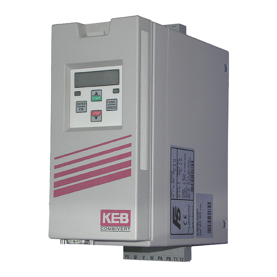
Seite 9: Abmessungen Und Anschlüsse
Produktbeschreibung Abmessungen und Anschlüsse U, V, W Anschluss für Servomotor PA, PB Anschluss Bremswiderstand T1, T2 Anschluss für Temperatursensor/-schalter L1, N/L2, L3 1/3-phasiger Netzanschluss (230 V-Klasse) L1, L2, L3 3-phasiger Netzanschluss (400 V-Klasse) ++, -- Gleichspannungsein-/ausgang für DC-Versorgungungsnetze 250...370 V DC (230 V-Klasse) 420...720 V DC (400 V-Klasse) Anschluss für Schutzleiter Eingangsspannung beachten, da 230 V (1/3-phasig) und 400 V-Klasse (3-phasig) -
Seite 10: Einbau Und Anschluss
• Alle Leitungen möglichst dicht an der Monta- geplatte verlegen - ideal im Metallkabelkanal. • COMBIVERT gut leitend mit der Montageplat- te montieren. Lack vorher entfernen. Weitere Hinweise zur EMV - gerechten Ver- drahtung finden Sie bei KEB im Internet. D - 10... -
Seite 11: Anschluss Des Leistungsteil
• DC-Versorgung 420…720 V DC (++, --) • DC-Versorgung 250…370 V DC (++, --) Achten Sie unbedingt auf die Anschlussspannung des KEB COMBIVERT. Ein 230 V- Gerät am 400 V-Netz wird sofort zerstört. Vertauschen Sie niemals die Netz- und Motorleitung. -
Seite 12: Netzanschluss
Einbau und Anschluss 3.3.3 Netzanschluss Netzanschluss 230 V 1-phasig Netzanschluss 230 V 3-phasig 3 x 1,5 mm² 4 x 1,5 mm² ���� ���� N/L2 N/L2 3 x 230 V AC 1 x 230 V AC Netzanschluss 400 V 3-phasig Absicherung •... -
Seite 13: Anschluss Der Temperaturerfassung
Einbau und Anschluss • Alle Steckverbindungen nur in spannungslosem Zustand stecken ! • Auf phasenrichtigen Anschluss des Motors achten ! • Motorleitung geschirmt Motorstecker ���� gr/ge �� � � � �� �� �� �� ext. Bremsspeisegerät Bremse + mit eigener Spannungs- Bremse –... -
Seite 14: Anschluss Eines Bremswiderstandes Mit Temperaturüberwachung Gemäß Ul
Bremswiderstände können sehr hohe Oberflächentemperaturen entwickeln, daher möglichst berührungssicher anbringen ! Geberinterfaceanschluss Die Stecker dürfen nur bei ausgeschaltetem Frequenzumrichter und ausgeschalteter Versorgungsspannung gezogen / gesteckt werden ! 3.4.1 Resolveranschluss bei KEB Motoren über Buchse X3A • Maximale Leitungslänge 50 m Gehäuse Gehäuse SIN-... -
Seite 15: Inkrementalgebereingang / -Nachbildung X3B
RJ45-Resolverstecker frei frei frei frei grün REF+ blau SIN+ SIN- gelb REF- grau COS+ rosa COS- 3.4.2 Inkrementalgebereingang / -nachbildung X3B Die Geberschnittstelle X3B ist umschaltbar von einer Inkrementalgebernachbildung auf einen Inkrementalgebereingang. Die Strichzahl der Nachbildung beträgt bei Geräten mit Resolverinterface immer 1024 Inkremente. -
Seite 16: Steuerkarte
Einbau und Anschluss Steuerkarte 3.5.1 Steuerklemmleiste X2A … • Anzugsmoment 0,22 0,25 Nm (2 lb inches) 1 2 5 7 8 10 11 12 13 16 18 19 21 22 24 25 26 • Abgeschirmte/verdrillte Leitungen verwenden • Schirm einseitig am Umrichter auf Erdpotential legen •... -
Seite 17: Anschluss Der Steuerklemmleiste
Einbau und Anschluss 3.5.2 Anschluss der Steuerklemmleiste Sollwertsignal Sollwertpotentiometer ��� 0…±10 V DC 3…10 kΩ � � � � � � Analogausgang �� � � � ±10 V DC max. 5 mA � � �� �� �� � �� externe Spannungsversorgung ��... -
Seite 18: Bedienung Des Gerätes
Standardkabels würde die PC-Schnittstelle zerstören. 4.1.2 Digitaloperator (Artikelnummer 00.F5.060-1000) Als Zubehör zur lokalen Bedienung des KEB COMBIVERT F5 ist ein Operator erhältlich. Um Fehlfunktionen zu vermeiden, muss der Umrichter vor dem Aufstecken / Abziehen des Operators in den Status noP (Reglerfreigabe öffnen) gebracht werden. Bei der Inbetriebnahme des Umrichters wird immer mit den zuletzt abgespeicherten Werten, bzw. -
Seite 19: Fernbedienung (Hsp5-Verlängerung)
Operatoren für spezielle Einsatzfälle (Profibus, Interbus, Sercos, CAN) bestückt werden. Weitere Informationen hierzu finden Sie auf unserer Homepage. Tastaturbedienung 4.2.1 Parameternummern und /-werte Beim Einschalten des KEB COMBIVERT F5 erscheint der Wert des Parameters CP.1. Mit der Funktionstaste wird zwischen Parameterwert FUNC. und Parameternummer gewechselt. -
Seite 20: Rücksetzen Von Fehlermeldungen
Durch ENTER wird nur die Fehlermeldung in der Anzeige zurückgesetzt. Um den Fehler selbst zurückzusetzen, muss erst die Ursache behoben werden und ein Reset oder ein Kaltstart erfolgen. 4.2.3 Passworteingabe Der KEB COMBIVERT ist mit einem umfassenden Passwortschutz ausgestattet. Abhängig vom eingegebenen Passwort sind folgende Modis möglich: Anzeige Modus CP_ro Endkundenmenü... -
Seite 21: Parameterbeschreibung
Anzeige durch ENTER bereits zurückgesetzt wurde (Fehler- LED im Operator blinkt noch). Statusmeldungen und Informationen über die Ursache und Beseitigung, finden Sie unter „www.keb.de => Dokumentation => Bedienungsanleitungen => Sonstiges => Serviceinformationen => Fehler- und Statusmeldungen.doc“. -
Seite 22: Cp.10 Konfiguration Drehzahlregelung
Werden Motoren mit ausgerichtetem Gebersystem verwendet, kann der durch das automatiche Abgleichen ermittelte Wert auch direkt unter CP.20 eingegeben werden. Die Abgleichwerte von bekannten Motoren der KEB COMBIVERT S4-Reihe, müssen mit der Polpaarzahl des Motors multipliziert werden. Die unteren 16 Bit des Ergebnisses müssen in CP.20 eingetragen werden. - Seite 23 CP-Parameter CP.21 Drehrichtungstausch Geber 1 Die Drehzahlanzeige unter CP.1 muss bei Rechtsdrehung des Motors von Hand positiv sein. Wenn das Vorzeichen nicht stimmt, müssen bei Geräten mit Resolver SIN+ und SIN- vertauscht werden. Dabei ist darauf zu achten, dass die Signale nicht mit dem inneren Schirm kurzgeschlossen werden.
-
Seite 24: Cp.35 Reaktion Auf Endschalterfehler
CP-Parameter Wert Funktion Scheinstrom (CP.4) > Schaltpegel Rechtslauf (nicht bei nOP, LS, Schnellhalt oder Fehler) Linkslauf (nicht bei nOP, LS, Schnellhalt oder Fehler) Warnung E.OL2 Stromregler in der Begrenzung Drehzahlregler in der Begrenzung Betrag ANOUT1 > Schaltpegel Betrag ANOUT2 > Schaltpegel ANOUT1 >... -
Seite 25: Zertifizierungen
Markt sind folgende zusätzliche Hinweise unbedingt zu beachten: • Der KEB COMBIVERT ist für einen Einsatz am Netz mit einem max. Kurzschlussstrom von Ieff = 10 kA (symmetrisch) bei max. 240 V AC, bzw. 480 V AC zu verwenden •... -
Seite 26: Weitere Anleitungen
Weitere Anleitungen Weitere Anleitungen Ergänzende Anleitungen und Hinweise zum Download finden Sie unter www.keb.de > Dokumentation > Betriebsanleitungen Allgemeine Anleitungen • Teil 1 EMV- und Sicherheitshinweise Gerätespezifische Anleitungen • Teil 2 Leistungsteile • Teil 3 Steuerteil Servicehinweise • Download von Parameterlisten •... - Seite 27 GB - 3...
- Seite 52 +49 5263 401-0 • fax: +49 5263 401-116 net: www.keb.de • mail: info@keb.de KEB Antriebstechnik GmbH & Co. KG KEB Italia S.r.l. Wildbacher Str. 5 • D–08289 Schneeberg Via Newton, 2 • I-20019 Settimo Milanese (Milano) fon: +49 3772 67-0 • fax: +49 3772 67-281 fon: +39 02 33500782 •...