Exsys EX-45352 Bedienungsanleitung

Verwandte Anleitungen für Exsys EX-45352


Inhaltszusammenfassung für Exsys EX-45352
- Seite 1 Bedienungsanleitung Vers. 1.1 / 29.02.12 EX-45352 RS-422/485 PCIe Board EX-45352IS RS-422/485 PCIe Board Surge Protection & Optical Isolation User Manual...
-
Seite 2: Inhaltsverzeichnis
Deutsch Seriell RS-422/485 PCIe Karte Inhaltsverzeichnis Beschreibung ··························································································· 3 Paketinhalt ······························································································· 3 Layout und Jumper Einstellungen ··························································· 4 3.1 Layout ······················································································································· 4 3.2 Octopus Kabel ··········································································································· 4 3.2 Jumper Einstellungen ································································································ 5 Hardware Installation ··············································································· 6 Treiber Installation ··················································································· 7 5.1 Windows 98 / ME / 2000 / XP/ Vista und 2003 Server ···············································... -
Seite 3: Beschreibung
Deutsch 1. Beschreibung Vielen Dank das Sie sich für die RS-422/485 PCIe Karte von EXSYS entschieden ha- ben. Sie ist eine Add-On Karte für den PCI-Express-Bus für Desktop, Workstation oder Server um eine High-Speed Datenübertragung herzustellen. Der Serielle Port ist kom- patible mit dem RS-422/485 Standard. -
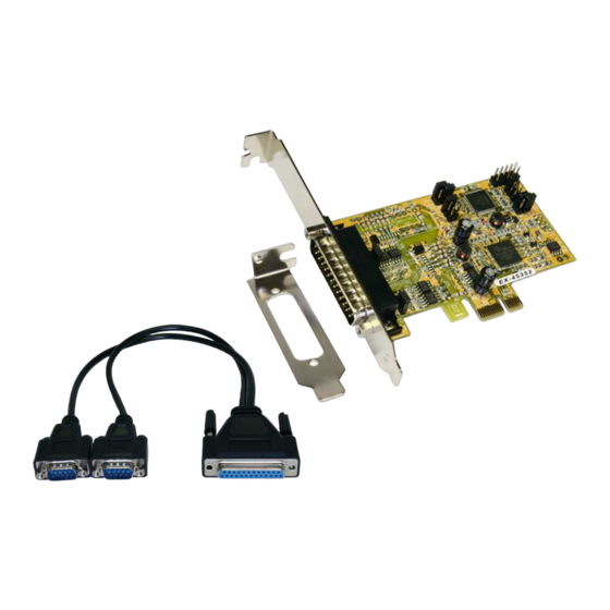
Seite 4: Layout Und Jumpereinstellungen
Deutsch Seriell RS-422/485 PCIe Karte 3. Layout und Jumpereinstellungen 3.1 Layout JP8: JP2, JP5: JP4: S1 S1 Abschlusswiderstand RS-485TXD Control RS-422/485 Ein/Ausschalten Mode Einstellung Nur für Testzwecke im Werk JP7: S2 RS-422/485 Mode Einstellung JP3, JP6: RS-485TXD Control JP9: S2 Abschlusswiderstand Ein/Ausschalten J2: DB25 Stecker für Octopus-Kabel 2 x 9 Pin 3.2 Octopus Kabel (DB25 Buchse zu 2 x DB9 Stecker) -
Seite 5: Jumper Einstellungen
Seriell RS-422/485 PCIe Karte Deutsch 3.3 Jumper-Einstellung Es gibt zwei Jumper-Reihen um die Ports S1 und S2 einzustellen 1. Mode Einstellungs-Jumper: JP4 für S1 und JP7 für S2 2. Abschlusswiderstand Jumper: JP8 für S1 und JP9 für S2 3. Echo oder No Echo Jumper: JP5 für S1 und JP6 für S2 4. -
Seite 6: Hardware Installation
Deutsch Seriell RS-422/485 PCIe Karte 4. TXD Control Einstellung Dieser Jumper wird verwendet im Mode RS-485 um das Steuersignal des Sender- Puffer zu kontrollieren. Es hat zwei Einstellungen. Die erste ist „MAN“ (manuell) und die zweite ist „AUT“ (automatisch). Die zweite ist die Werkseinstellung und sollte nicht verstellt werden. -
Seite 7: Treiber Installation
Seriell RS-422/485 PCIe Karte Deutsch 5. Treiber Installation Anmerkung! Bitte lassen Sie Windows nicht automatisch nach den Treibern suchen, da dies wegen den INF Files zu Problemen führen könnte. Stattdessen durchsuchen sie manuell den Treiber an der richtigen Stelle (Ordner) auf der mitgelieferten CD. Bild 1 Die Treiber finden Sie in dem Order für das installierte Be-... -
Seite 8: Verdrahtungsübersicht
Deutsch Seriell RS-422/485 PCIe Karte 6. Verdrahtungsübersicht Anschlussbelegung DB 9M DB 9M DB 9M DB 9M 9 Pin D-SUB Stecker (S1 und S2) Pin Signal Pin Signal Pin Signal TXD- (DATA-) RXD- TXD+ (DATA+) RXD+ RS-485 (2 Draht) Verkabelung DATA(-) Pin 1 Pin 1 DATA (-)