Inhaltsverzeichnis
Werbung
Verfügbare Sprachen
Verfügbare Sprachen
Quicklinks
Werbung
Inhaltsverzeichnis

Verwandte Anleitungen für EuroLite LED IP T1000 QCL


Inhaltszusammenfassung für EuroLite LED IP T1000 QCL
-
Seite 2: Inhaltsverzeichnis
Diese Bedienungsanleitung gilt für die Artikelnummer 51914108 This user manual is valid for the article number 51914108 Das neueste Update dieser Bedienungsanleitung finden Sie im Internet unter: You can find the latest update of this user manual in the Internet under: www.eurolite.de 2/40 00102016, Version 1.0... -
Seite 3: Einführung
- sich die letzte Version der Anleitung im Internet herunter laden EINFÜHRUNG Wir freuen uns, dass Sie sich für eine EUROLITE LED IP T1000 QCL entschieden haben. Wenn Sie nachfolgende Hinweise beachten, sind wir sicher, dass Sie lange Zeit Freude an Ihrem Kauf haben werden. - Seite 4 Der Aufbau entspricht der Schutzklasse I. Der Netzstecker darf nur an eine Schutzkontakt-Steckdose angeschlossen werden, deren Spannung und Frequenz mit dem Typenschild des Gerätes genau übereinstimmt. Ungeeignete Spannungen und ungeeignete Steckdosen können zur Zerstörung des Gerätes und zu tödlichen Stromschlägen führen. Den Netzstecker immer als letztes einstecken.
-
Seite 5: Bestimmungsgemässe Verwendung
BESTIMMUNGSGEMÄSSE VERWENDUNG Bei diesem Gerät handelt es sich um einen Architektur-Scheinwerfer, mit dem sich dekorative Lichteffekte erzeugen lassen. Dieses Produkt ist für den Anschluss an 100-240 V, 50/60 Hz Wechselspannung zugelassen. Das Gerät ist gegen Strahlwasser geschützt (Schutzart IP 65) und kann deshalb sowohl in Innenräumen als auch im Freien verwendet werden. -
Seite 6: Gerätebeschreibung
Der Serienbarcode darf niemals vom Gerät entfernt werden, da ansonsten der Garantieanspruch erlischt. Wird das Gerät anders verwendet als in dieser Bedienungsanleitung beschrieben, kann dies zu Schäden am Produkt führen und der Garantieanspruch erlischt. Außerdem ist jede andere Verwendung mit Gefahren, wie z. -
Seite 7: Geräteübersicht
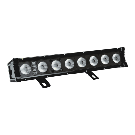
Geräteübersicht (1) Gehäuse (2) Spannungsversorgungseingang/ DMX-Eingang (3) LED/Linse (4) Enter-Taste (5) Down-Taste (6) Up-Taste (7) Menu-Taste (8) Display (9) Spannungsversorgungsausgang/DMX-Ausgang (10) Entlüftungsschraube (11) Spannungsversorgungseingang (12) DMX-Eingang (13) Hängebügel/Standfuß (14) Feststellschraube (15) Kühlrippen INSTALLATION Befestigung Der Installationsort muss so gewählt werden, dass das Gerät absolut plan an einem festen, erschütterungs- freien, schwingungsfreien und feuerfesten Ort befestigt werden kann. -
Seite 8: Überkopfmontage
Vorgehensweise: Schritt 1: An den Montagebügeln des Gerätes befinden sich Löcher zur Installation. Schritt 2: Halten Sie das Gerät mit den Montagebügeln an die Stelle, wo es installiert werden soll. Schritt 3: Markieren Sie Ihre Bohrlöcher mit einem Bleistift oder einem geeigneten Werkzeug. Schritt 4: Bohren Sie die Löcher. - Seite 9 BRANDGEFAHR! Achten Sie bei der Installation des Gerätes bitte darauf, dass sich im Abstand von mind. 0,5 m keine leicht entflammbaren Materialien (Deko, etc.) befinden. Die Montagebügel an der Geräterückseite lassen sich durch verschieben auf die gewünschte Position einstellen. Lösen Sie dazu die beiden Fixierschrauben aus Kunststoff mit einem geeigneten Schraubendreher.
-
Seite 10: Dmx512-Ansteuerung
DMX512-Ansteuerung Achten Sie darauf, dass die Adern der Datenleitung an keiner Stelle miteinander in Kontakt treten. Die Geräte werden ansonsten nicht bzw. nicht korrekt funktionieren. Beachten Sie, dass die Startadresse abhängig vom verwendeten Controller ist. Unbedingt Bedienungsanleitung des verwendeten Controllers beachten. Zur Steckverbindung zwischen Controller und Gerät verwenden Sie bitte das beiliegende Adapterkabel. -
Seite 11: Anschluss Ans Netz
Eindringen von Feuchtigkeit und Schmutz zu verhindern. BEDIENUNG Wenn Sie das Gerät an die Spannungsversorgung angeschlossen haben, nimmt die LED IP T1000 QCL den Betrieb auf. Das LED Display leuchtet auf und Sie können die gewünschten Einstellungen mit den Tasten MENU, UP, DOWN und ENTER auswählen. -
Seite 12: Control Board
Control Board Das Control Board bietet mehrere Möglichkeiten: so lassen sich z. B. die DMX-Startadresse eingeben oder das vorprogrammierte Programm abspielen. Drücken Sie die Menu-Taste, so dass sich das Display einschaltet. Über die Up-/ Down Taste können Sie sich im Hauptmenü bewegen. Zur Auswahl des gewünschten Menüpunktes drücken Sie die Enter-Taste. Durch Drücken der Up/Down-Tasten können Sie die Auswahl verändern. - Seite 13 Display-Abschaltung DISY ON – immer an 2MIN 2MIN – Abschaltung nach 2 Minuten Tastensperre YES – Tastensperre nach 2 Minuten. Um LOCK YES/NO die Tastensperre aufzuheben, eine beliebige Taste für 10 Sekunden gedrückt halten. 0-255 CT01 – 0-255 Individuelle Kunden-Farbeinstellung CTST CT10 0-255...
-
Seite 14: Dmx-Modus
Bitte vergewissern Sie sich, dass sich die Steuerkanäle nicht mit anderen Geräten überlappen, damit die LED IP T1000 QCL korrekt und unabhängig von anderen Geräten in der DMX-Kette funktioniert. Werden mehrere LED IP T1000 QCL auf eine Adresse definiert, arbeiten sie synchron. -
Seite 15: Dmx-Protokoll
DMX-Protokoll 3-Kanal-Modus Steuerkanal 1 - Dimmer Decimal Hexad. Percentage S/F Eigenschaft 0 255 00 FF 0% 100% Allmähliche Einstellung der Dimmerintensität von 0 bis 100 % Steuerkanal 2 - Weiß Decimal Hexad. Percentage S/F Eigenschaft 0 255 00 FF 0% 100% Weiß... - Seite 16 5-Kanal-Modus Steuerkanal 1 - Dimmer Decimal Hexad. Percentage S/F Eigenschaft 0 255 00 FF 0% 100% Allmähliche Einstellung der Dimmerintensität von 0 bis 100 % Steuerkanal 2 - Rot Decimal Hexad. Percentage S/F Eigenschaft 0 255 00 FF 0% 100% Rot (0=aus, 255=100% rot) Steuerkanal 3 - Grün Decimal Hexad.
- Seite 17 Steuerkanal 6 - Strobe-Effekt Decimal Hexad. Percentage S/F Eigenschaft 00 00 0% 0% Keine Funktion 01 05 0% 2% 6 10 06 0A 2% 4% Keine Funktion 11 255 0B FF 4% 100% Strobe-Effekt mit zunehmender Geschwindigkeit 7-Kanal-Modus Steuerkanal 1 - Dimmer Decimal Hexad.
- Seite 18 21 30 15 1E 18% 29% Exponentielle Dimmerkurve, Ansprechverhalten LED 31 40 1F 28 30% 41% Umgekehrt exponentielle Dimmerkurve, Ansprechverhalten LED 41 50 29 32 42% 53% S-förmige Dimmerkurve, Ansprechverhalten LED 51 60 33 3C 53% 65% Lineare Dimmerkurve, Ansprechverhalten Halogenlampe 61 70 3D 46 65% 76%...
- Seite 19 11 15 0B 0F 4% 6% CT01 - Farbeinstellung aus Control Board (CTST, custom color set) 16 20 10 14 6% 8% CT02 - Farbeinstellung aus Control Board (CTST, custom color set) 21 25 15 19 8% 10% CT03 - Farbeinstellung aus Control Board (CTST, custom color set) 26 30 1A 1E 10% 12%...
-
Seite 20: Reinigung Und Wartung
92 130 5C 82 36% 51% Rot zunehmend / Grün 100% / Blau 0% 131 131 83 83 51% 51% Gelb 132 170 84 AA 52% 67% Rot 100% / Grün abnehmend / Blau 0% 171 171 AB AB 67% 67% 172 210 AC D2 67% 82% Rot 100% / Grün 0% / Blau zunehmend... -
Seite 21: Technische Daten
EUROLITE Sicherungsseil A 4x1000mm bis 15kg silber Best.-Nr. 58010320 EUROLITE Sicherungsseil A 4x1000mm bis 15kg sw Best.-Nr. 58010344 EUROLITE 230V-Leitung für LED IP PAR/IP Pad 5m Best.-Nr. 51914149 EUROLITE DMX-Leitung für LED IP Par, 5m Best.-Nr. 51914150 EUROLITE Netzanschlusskabel IP-Par, 1,8m, 230V Best.-Nr. -
Seite 22: Introduction
- download the latest version of the user manual from the Internet INTRODUCTION Thank you for having chosen a EUROLITE LED IP T1000 QCL. If you follow the instructions given in this manual, we are sure that you will enjoy this device for a long period of time. -
Seite 23: Health Hazard
Always plug in the power plug last. The power plug must always be inserted without force. Make sure that the plug is tightly connected with the outlet. Never let the power-cord come into contact with other cables! Handle the power-cord and all connections with the mains with particular caution! Never touch them with wet hands, as this could lead to mortal electrical shock. - Seite 24 The maximum relative humidity is 100 % with an ambient temperature of 25° C. This device must only be operated in an altitude between -20 and 2000 m over NN. This device is designed for professional use. Do not shake the device. Avoid brute force when installing or operating the device. When choosing the installation-spot, please make sure that the device is not exposed to extreme heat, moisture or dust.
-
Seite 25: Description Of The Device
DESCRIPTION OF THE DEVICE Features Versatile LED architectural lighting (IP 65) with eight QCL LEDs by CREE • Equipped with 8 CREE QCL LEDs in the colors red, green, blue and white • Flicker-free projection • 3, 4, 5, 6, 7 or 10 DMX channels selectable •... -
Seite 26: Installation
INSTALLATION Attachment The device must only be installed absolutely planar at a vibration-free, oscillation-free and fire-resistant location. The device must be installed out of the reach of people. The device must always be installed via all fixation holes. Do only use appropriate screws and make sure that the screws are properly connected with the ground. -
Seite 27: Danger Of Fire
Procedure: The device should be installed outside areas where persons may walk by or be seated. IMPORTANT! OVERHEAD RIGGING REQUIRES EXTENSIVE EXPERIENCE, including (but not limited to) calculating working load limits, installation material being used, and periodic safety inspection of all installation material and the device. -
Seite 28: Dmx512 Control
DMX512 control The wires must not come into contact with each other, otherwise the devices will not work at all, or will not work properly. Please note, the starting address depends upon which controller is being used. For the plug connection between controller and the device please use the enclosed adapter cable. For this purpose, connect the DMX input plug of the device with the adapter cable. -
Seite 29: Master/Slave Operation
Please make sure that open contacts are closed with caps in order to avoid humidity and dirt in the device. OPERATION After you connected the effect to the mains, the LED IP T1000 QCL starts running. The LED display lights up and you can now choose the desired settings via the buttons MENU, UP, DOWN and ENTER. -
Seite 30: Stand-Alone Mode
Stand-alone Mode In the stand-alone mode, the LED IP T1000 QCL can be used without DMX-controller. Disconnect the LED IP T1000 QCL from the DMX-controller. Control Board The Control Board offers several features: you can simply set the starting address or run the pre- programmed program. - Seite 31 Display shutoff ON – permanent on DISY 2MIN - shut off the display after 2 2MIN minutes Keylock LOCK YES/NO YES – Keylock after 2 minutes. To unlock press any key for 10 seconds. 0-255 CT01 – 0-255 Individual customer color setting CTST CT10 0-255...
-
Seite 32: Dmx Mode
LED IP T1000 QCL will respond to the controller. Please, be sure that you don’t have any overlapping channels in order to control each LED IP T1000 QCL correctly and independently from any other fixture on the DMX-chain. If several LED IP T1000 QCL are addressed similarly, they will work synchronically. -
Seite 33: Dmx Protocol
DMX Protocol 3 channel mode Control-channel 1 - Dimmer Decimal Hexad. Percentage S/F Feature 0 255 00 FF 0% 100% Gradual adjustment of the dimmer intensity from 0 to 100 % Control-channel 2 - White Decimal Hexad. Percentage S/F Feature 0 255 00 FF 0% 100% White (0=off, 255=100% white) - Seite 34 5 channel mode Control-channel 1 - Dimmer Decimal Hexad. Percentage S/F Feature 0 255 00 FF 0% 100% Gradual adjustment of the dimmer intensity from 0 to 100 % Control-channel 2 - Red Decimal Hexad. Percentage S/F Feature 0 255 00 FF 0% 100% Red (0=off, 255=100% red) Control-channel 3 - Green...
- Seite 35 Control-channel 6 - Strobe effect Decimal Hexad. Percentage S/F Feature 00 00 0% 0% No function 01 05 0% 2% 6 10 06 0A 2% 4% No function 11 255 0B FF 4% 100% Strobe effect with increasing speed 7 channel mode Control-channel 1 - Dimmer Decimal Hexad.
- Seite 36 31 40 1F 28 30% 41% Inverse square dimmer curve, response characteristics of LED 41 50 29 32 42% 53% S-shaped dimmer curve, response characteristics of halogen LED 51 60 33 3C 53% 65% Linear dimmer curve, response characteristics of halogen lamp 61 70 3D 46 65% 76%...
- Seite 37 21 25 15 19 8% 10% CT03 - Control Board setting color (CTST, custom color set) 26 30 1A 1E 10% 12% CT04 - Control Board setting color (CTST, custom color set) 31 35 1F 23 12% 14% CT05 - Control Board setting color (CTST, custom color set) 36 40 24 28 14% 16%...
-
Seite 38: Cleaning And Maintenance
132 170 84 AA 52% 67% Red 100% / green decreasing / blue 0% 171 171 AB AB 67% 67% 172 210 AC D2 67% 82% Red 100% / green 0% / blue increasing 211 211 D3 D3 83% 83% Magenta 212 250 D4 FA 83% 98% Red decreasing / green 0% / blue 100%... -
Seite 39: Technical Specifications
EUROLITE TPC-10 Coupler, silver No. 59006856 EUROLITE TPC-10 Coupler, black No. 59006858 EUROLITE Safety bond A 4x1000mm up to 15kg silver No. 58010320 EUROLITE Safety bond A 4x1000mm up to 15kg black No. 58010344 EUROLITE 230V cable for LED IP PAR/IP Pad 5m No. - Seite 40 Eurolite is a brand of Steinigke Showtechnic GmbH Andreas-Bauer-Str. 5 97297 Waldbüttelbrunn Germany D00101995 Version 1.0 Publ. 24/08/2016...