
Verwandte Anleitungen für WIKA CPB5800


Inhaltszusammenfassung für WIKA CPB5800
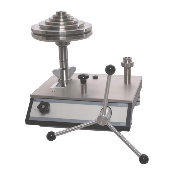
- Seite 1 Operating Instructions Betriebsanleitung Pressure Balance Kolbenmanometer CPB5800 Pressure Balance CPB5800...
- Seite 2 Betriebsanleitung Kolbenmanometer Seite 38 - 72 Information This symbol provides you with information, notes and tips. Warning! This symbol warns you against actions that can cause injury to people or damage to the instrument. WIKA Operating Instructions Pressure Balance Version 1.1...
-
Seite 3: Inhaltsverzeichnis
5.1.1.1 Procedure for single-range piston-cylinder system 1,600 psi or 120 bar ....26 5.1.1.2 Procedure for single-range piston-cylinder system 4,000 psi or 300 bar ....27 5.1.1.3 Procedure for all dual-range piston-cylinder systems ........... 28 5.1.2 Mass set ..........................29 WIKA Operating Instructions Pressure Balance Version 1.1... - Seite 4 5.3.2 Filling in of hydraulic pressure medium ................29 5.3.3 Venting of the System (after Complete Filling only) ............30 5.4 Recalibration ..........................30 6. Specifications ....................31 7. Tables of masses ....................34 8. Accessories ..........................36 WIKA Operating Instructions Pressure Balance Version 1.1...
-
Seite 5: General
1. General 1.1 General Instructions In the following chapters detailed information on the CPB5800 pressure balance and its proper use can be found. Should you require further information, or should there be problems which are not dealt within detail in... -
Seite 6: Safety Instructions
2. Trouble-free operation and reliability of the device can only be guaranteed so long as the conditions stated under "Setting up the device" are taken into consideration. 3. The CPB5800 always has to be handled with the care required for any precision instrument (protect from humidity, impacts and extreme temperatures). The device, the piston-cylinder-system and the mass-set must be handled with care (don't throw, hit, etc.) and protected from... -
Seite 7: Product Description
Piston-cylinder measuring system Pressure is defined as a quotient of force and area. Correspondingly, the core of the CPB5800 is a very precisely manufactured piston/cylinder system. The piston and cylinder are manufactured from hardened steel and tungsten carbide, respectively, and are very well protected in a solid stainless steel/hardened tool steel housing against impacts or contamination from outside. - Seite 8 Force F Force F High-pressure piston Low-pressure piston =High-pressure cylinder Cross-sectional area A Pressure p Pressure p CPS5800 single-range piston-cylinder system CPS5800 dual-range piston-cylinder system WIKA Operating Instructions Pressure Balance Version 1.1...
-
Seite 9: Basic Principle Of The Pressure Balance
Locale gravity at application site: 9.811053 m/s Nominal pressure: 100 bar 81105 Local 0449 True pressure: Nominal 80665 dard Without the correction, measurements would differ from the nominal applied pressure by 0.05%. WIKA Operating Instructions Pressure Balance Version 1.1... -
Seite 10: Temperature (Piston/Cylinder)
The air density is typically 1.2 kg/m The density of the masses (non-magnetic steel) is 7900 kg/m A fluctuation of 5% in the relative humidity causes an additional uncertainty in the measurement of about 0.001%. WIKA Operating Instructions Pressure Balance Version 1.1... -
Seite 11: How The Cross-Sectional Area Responds To Pressure
Without the correction, measurements would differ from the nominal applied pressure by 0.01%. 2.4 Arrangement of control elements The CPB5800 instrument bases are available in 2 variants: Standard hydraulic base - up to max 1,200 bar / 16,000 psi - with integrated pressure generation through priming pump and spindle pump - tubing made of stainless steel (1.4404), 6 x 2 mm... -
Seite 12: Standard Hydraulic Base
Rear view Interface to float position sensor (optional and in combination with CPU6000 only) Interface to piston temperature sensor (optional and in combination with CPU6000 only) Rotating foot studs for levelling base WIKA Operating Instructions Pressure Balance Version 1.1... -
Seite 13: High-Pressure Hydraulic Base
Rear view Interface to float position sensor (optional and in combination with CPU6000 only) Interface to piston temperature sensor (optional and in combination with CPU6000 only) Rotating foot studs for levelling base WIKA Operating Instructions Pressure Balance Version 1.1... -
Seite 14: Commissioning And Operation
If the piston unit has not been specially calibrated, the accuracy of the unit will be reduced, and this should be taken into account. WIKA Operating Instructions Pressure Balance Version 1.1... -
Seite 15: Installing The Piston-Cylinder System
The connection for the piston-cylinder system in the instrument base is available in 2 different versions: - Connection for piston-cylinder system with G3/4 B (male) thread (see section 3.1.3.1) - Connection for piston-cylinder system with ConTect quick connector, not for the 1,400 bar-version (see section 3.1.3.2) WIKA Operating Instructions Pressure Balance Version 1.1... -
Seite 16: Connection For Piston-Cylinder System With G3/4 B (Male) Thread
For an exact alignment of the device, the spirit level may be removed from the base plate and placed on the top of the fitted piston-cylinder system. This will ensure the most accurate levelling of the piston-cylinder system. Temperature sensor, Oil collecting tray optional WIKA Operating Instructions Pressure Balance Version 1.1... -
Seite 17: Connection For Piston-Cylinder System With Contect Quick Connector
This will ensure the most accurate levelling of the piston-cylinder system. Put spirit level on top of piston O-ring 4 x 2.2 (see accessories section 8.) WIKA Operating Instructions Pressure Balance Version 1.1... -
Seite 18: Connecting The Device Under Test
Open the outlet valve slowly, any trapped air will escape into the tank This procedure may need to be repeated 1 to 2 times in order to remove all trapped air. The device is now ready to use. WIKA Operating Instructions Pressure Balance Version 1.1... -
Seite 19: Operation
As there is only a small pressure change required between the piston floating/not floating we recommend turning the pump spindle slowly and evenly clockwise. The piston and thus the test pressure as well now remain stable for several minutes. WIKA Operating Instructions Pressure Balance Version 1.1... -
Seite 20: Procedure For Single-Range Piston-Cylinder System 4,000 Psi Or 300 Bar
As there is only a small pressure change required between the piston floating/not floating we recommend turning the pump spindle slowly and evenly clockwise. The piston and thus the test pressure as well now remain stable for several minutes. WIKA Operating Instructions Pressure Balance Version 1.1... -
Seite 21: Procedure For All Dual-Range Piston-Cylinder Systems
To confirm this, the operator can press down lightly (use index finger) onto the top of the masses applied. If the piston and masses appear to bounce (move freely up and down) the piston unit is at pressure value of masses applied. WIKA Operating Instructions Pressure Balance Version 1.1... -
Seite 22: Next Pressure Level
Attention: In this case the piston must stay in the lower position! Caution: The piston is lowered very quickly just before equilibrium is achieved. Caution: Do not remove masses completely from the piston-cylinder system under pressure. WIKA Operating Instructions Pressure Balance Version 1.1... -
Seite 23: Disassembly
In order to remove the star handle from the spindle pump, the spring-loaded thrust pad must be pressed downward with the aid of a small screwdriver, or a ball-point pen. The star handle may now be pulled off toward the front. Spring-loaded thrust pad WIKA Operating Instructions Pressure Balance Version 1.1... -
Seite 24: Troubleshooting Measures
Doing so could cause lasting damage that would seriously affect measurement accuracy. The piston must be cleaned (see section 5.1.1) Further help can be found through WIKA's Calibration Technology Department or DH-Budenberg Customer Service. WIKA Operating Instructions Pressure Balance Version 1.1... -
Seite 25: Maintenance And Care
We recommend you to clean the piston-cylinder systems after every use as needed. Poor sensitivity or short free turning duration are indications the system needs to be cleaned. To do this, remove the piston-cylinder system from the base and disassemble it as described in the following references. WIKA Operating Instructions Pressure Balance Version 1.1... -
Seite 26: Procedure For Single-Range Piston-Cylinder System 1,600 Psi Or 120 Bar
Never touch the cleaned piston with your bare hands. The natural dermal-grease can cause a contamination of the piston-cylinder system. Never use excess force to fit the piston to the cylinder, permanent damage can occur. The system is now ready to use again. WIKA Operating Instructions Pressure Balance Version 1.1... -
Seite 27: Procedure For Single-Range Piston-Cylinder System 4,000 Psi Or 300 Bar
Never touch the cleaned piston with your bare hands. The natural dermal-grease can cause a contamination of the piston-cylinder system. Never use excess force to fit the piston to the cylinder, permanent damage can occur. The system is now ready to use again. WIKA Operating Instructions Pressure Balance Version 1.1... -
Seite 28: Procedure For All Dual-Range Piston-Cylinder Systems
Never touch the cleaned piston with your bare hands. The natural dermal-grease can cause a contamination of the piston-cylinder system. Never use excess force to fit the piston to the cylinder, permanent damage can occur. The system is now ready to use again. WIKA Operating Instructions Pressure Balance Version 1.1... -
Seite 29: Mass Set
Rotate the spindle pump counter-clockwise until it reaches the rear stop. The pressure medium is automatically transferred out of the tank into the system. Close the tank opening with the locking screw WIKA Operating Instructions Pressure Balance Version 1.1... -
Seite 30: Venting Of The System (After Complete Filling Only)
10 Huntsman Drive, Northbank Ind. Est. Irlam, Manchester • M44 5EG United Kingdom Tel.: (+44) 844 406 0086 Fax: (+44) 844 406 0087 E-Mail: sales@dh-budenberg.co.uk WIKA Alexander Wiegand SE & Co. KG Alexander Wiegand Strasse D-63911 Klingenberg Tel.: (+49) 9372/132-0 Fax: (+49) 9372/132-406 E-Mail: info@wika.com... -
Seite 31: Specifications
Carrying case for 400 x 310 x 310 mm (W x H x D) standard mass sets Storage case for piston- 300 x 265 x 205 mm (W x H x D) cylinder systems (optional) WIKA Operating Instructions Pressure Balance Version 1.1... - Seite 32 Calibration Option: UKAS calibration certificate 1) 2) 1) For standard accuracy UKAS calibration certificate only available as pressure calibration. 2) Premium accuracy requires UKAS area and mass calibration Approvals and certificates, see website WIKA Operating Instructions Pressure Balance Version 1.1...
- Seite 33 (please contact WIKA sales language team for further information) Factory calibration certificate Dimensions Detailed section view 1,400 bar high-pressure version -with high-pressure shut-off valve -no ConTect quick-release connector possible Dimensions are identical WIKA Operating Instructions Pressure Balance Version 1.1...
-
Seite 34: Tables Of Masses
The following tables show the amount of masses per measuring range within a mass set with their resulting nominal pressures. Should you not operate the device under reference conditions (ambient temperature 20°C, air pressure 1013 mbar, relative humidity 40%), the corrections according to section 2.3 must be considered. WIKA Operating Instructions Pressure Balance Version 1.1... - Seite 35 Pressure Balance CPB5800 WIKA Operating Instructions Pressure Balance Version 1.1...
-
Seite 36: Accessories
WIKA-CAL PC software – Weight calculator With the demo version of the WIKA-CAL software and a CPB series pressure balance, the masses to be applied and the corresponding reference pressure can be determined. - Seite 37 Special test-item adapter with quick connect, for the matching to the ConTect system 2152634 mechanism, operation as a comparison test pump is possible Electrical piston drive unit for 700 bar, 1,200 bar and 1,400 bar measuring ranges (AC 14031260 230 V/50 Hz) WIKA Operating Instructions Pressure Balance Version 1.1...
- Seite 38 Kolbenmanometer CPB5800 Information Dieses Zeichen gibt Ihnen Informationen, Hinweise oder Tipps. Warnung! Dieses Symbol warnt Sie vor Handlungen, die Schäden an Personen oder am Gerät verursachen können. WIKA Betriebsanleitung Kolbenmanometer Version 1.1...
- Seite 39 5.1.1.1 Vorgehensweise bei Einzel-Kolbenzylindersystem 1.600 psi oder 120 bar ....62 5.1.1.2 Vorgehensweise bei Einzel-Kolbenzylindersystem 4,000 psi oder 300 bar ....63 5.1.1.3 Vorgehensweise bei allen Doppel-Kolbenzylindersystemen ........64 5.1.2 Massensatz ..........................65 5.2 Verschleißteile .......................... 65 WIKA Betriebsanleitung Kolbenmanometer Version 1.1...
- Seite 40 5.3.1 Hydraulisches Druckmedium entfernen ................65 5.3.2 Hydraulisches Druckmedium einfüllen ................65 5.3.3 Entlüftung des Systems (nur nach Komplettbefüllung) ............ 66 5.4 Rekalibrierung .......................... 66 6. Technische Daten ...................... 67 7. Gewichtstabellen ...................... 70 8. Zubehör ...................... 72 WIKA Betriebsanleitung Kolbenmanometer Version 1.1...
-
Seite 41: Allgemeines
Außerdem weisen wir darauf hin, dass der Inhalt dieser Betriebsanleitung nicht Teil einer früheren oder bestehenden Vereinbarung, Zusage oder Rechtsverhältnisses ist oder diese abändern soll. Sämtliche Verpflichtungen der WIKA Alexander Wiegand SE & Co. KG ergeben sich aus dem jeweiligen Kaufvertrag und den Allgemeinen Geschäftsbedingungen der WIKA Alexander Wiegand SE &... -
Seite 42: Sicherheitshinweise
2. Die einwandfreie Funktion und Betriebssicherheit des Gerätes kann nur unter Berücksichtigung der im Kapitel "Aufstellung des Gerätes“ beschriebenen Bedingungen eingehalten werden. 3. Das CPB5800 ist stets mit der für jedes Präzisionsgerät erforderlichen Sorgfalt zu behandeln (vor Nässe, Stößen und extremen Temperaturen schützen). Gerät, Kolbenzylindersystem und Massensatz müssen pfleglich behandelt werden (nicht werfen, aufschlagen, etc.) und sind vor... -
Seite 43: Produktbeschreibung
Einsatz vor Ort, in der Wartung und im Service geeignet. Kolbenzylinder-Messsystem Druck ist definiert als der Quotient aus Kraft und Fläche. Das Herzstück des CPB5800 bildet dementsprechend ein sehr präzise gefertigtes Kolbenzylindersystem. Die Kolben und Zylinder sind aus gehärtetem Stahl bzw. Wolfram Carbid gefertigt und in einem massiven Gehäuse aus Edelstahl/gehärtetem Werkzeugstahl sehr gut geschützt gegen Stöße oder Verschmutzung von... -
Seite 44: Funktionsweise
Minuten, so dass problemlos die Druckwerte zur Vergleichsmessung abgelesen oder auch umfangreichere Justagearbeiten am Prüfling vorgenommen werden können. Kraft F Kraft F Hochdruckkolben Niederdruckkolben =Hochdruckzylinder Querschnitts- fläche A Druck p Druck p Einzel-Kolbenzylindersystem CPS5800 Doppel-Kolbenzylindersystem CPS5800 WIKA Betriebsanleitung Kolbenmanometer Version 1.1... -
Seite 45: Grundprinzip Kolbenmanometer
Lokaler Schwerewert bei der Herstellung: 9,806650 m/s Lokaler Schwerewert am Einsatzort: 9,811053 m/s Nominal-Druck: 100 bar 81105 lokal 0449 Wahrer Druck: Nominal 80665 Norm Ohne Korrektur würde um 0,05 % „falsch“ gemessen werden. WIKA Betriebsanleitung Kolbenmanometer Version 1.1... -
Seite 46: Temperatur (Kolben-Zylinder)
Masse Nominalmas Massendich Die Luftdichte ist typischerweise 1,2 kg/m Die Dichte der Massen (nichtmagnetischer Stahl): 7900 kg/m Aus einer Schwankung der Luftdichte um 5% ergibt sich eine zusätzliche Messunsicherheit von ca. 0,001%. WIKA Betriebsanleitung Kolbenmanometer Version 1.1... -
Seite 47: Druckabhängigkeit Der Querschnittsfläche
1000 Ohne Korrektur würde um 0,01 % „falsch“ gemessen werden. 2.4 Anordnung der Bedienelemente Die CPB5800 Basisgeräte sind in 2 Ausführungen erhältlich: Basement hydraulisch Standard - bis max. 1.200 bar / 16.000 psi - mit integrierter Druckerzeugung über Vordruckpumpe und Spindelpumpe - Verrohrung aus CrNi-Stahl (1.4404), 6 x 2 mm... -
Seite 48: Basement Hydraulisch Standard
ConTect- Prüflingsanschluss Schnellspann- aufnahme) Libelle Vordruckpumpe Spindelpumpe Frontansicht Auslass- ventil Rückansicht Schnittstelle zum Schwebepositionssensor (optional und nur in Kombination mit CPU6000) Schnittstelle zum Kolbentemperaturfühler (optional und nur in Kombination mit CPU6000) drehbare Füße WIKA Betriebsanleitung Kolbenmanometer Version 1.1... -
Seite 49: Basement Hydraulisch Hochdruck
G3/4 B Außen- gewinde Libelle Vordruckpumpe Spindelpumpe Frontansicht Auslass- ventil Rückansicht Schnittstelle zum Schwebepositionssensor (optional und nur in Kombination mit CPU6000) Schnittstelle zum Kolbentemperaturfühler (optional und nur in Kombination mit CPU6000) drehbare Füße WIKA Betriebsanleitung Kolbenmanometer Version 1.1... -
Seite 50: Inbetriebnahme Und Betrieb
Druckmedium hergestellt wurden, haben ihre kalibrierte Masse, die auf den Auftrieb und die Oberflächenspannung dieser Flüssigkeit angepasst wurde. Wenn das Kolbenzylindersystem nicht speziell kalibriert wurde, wird die Genauigkeit des Geräts geringer sein, und dies sollte berücksichtigt werden. WIKA Betriebsanleitung Kolbenmanometer Version 1.1... -
Seite 51: Einbau Des Kolbenzylindersystems
Messbereichsabstufung gewählt. Bei der Kolbenaufnahme im Basement wird zwischen 2 Ausführungen unterschieden: - Kolbenaufnahme mit G3/4 B Außengewinde (siehe Pkt. 3.1.3.1) - Kolbenaufnahme mit ConTect-Schnellverschluss, nicht bei 1.400 bar-Version (siehe Pkt. 3.1.3.2) WIKA Betriebsanleitung Kolbenmanometer Version 1.1... -
Seite 52: Kolbenaufnahme Mit G3/4 B Außengewinde
Sitz und Verschleiß überprüfen. Gegebenenfalls austauschen. Zum exakten Ausrichten des Gerätes kann die Libelle aus der Basisplatte herausgenommen werden und auf die Oberseite des eingespannten Kolbenzylindersystems aufgelegt werden. Hierdurch ist die genaueste Referenzierung zum Kolbenzylindersystem gegeben. WIKA Betriebsanleitung Kolbenmanometer Version 1.1... -
Seite 53: Kolbenaufnahme Mit Contect-Schnellverschluss
Zum exakten Ausrichten des Gerätes kann die Libelle aus der Basisplatte herausgenommen werden und auf die Oberseite des eingespannten Kolbenzylindersystems aufgelegt werden. Hierdurch ist die genaueste Referenzierung zum Kolbenzylindersystem gegeben. Libelle auflegen O-Ring 4 x 2,2 (siehe Zubehör Pkt. 8.) WIKA Betriebsanleitung Kolbenmanometer Version 1.1... -
Seite 54: Anschluss Des Prüflings
Schwebezustand gehen. Auslassventil langsam öffnen, vorhandene Lufteinschlüsse entweichen in den Tank Gegebenenfalls ist dieser Vorgang 1-2 mal zu wiederholen, um sämtliche Lufteinschlüsse zu entfernen. Das Gerät ist nun einsatzbereit WIKA Betriebsanleitung Kolbenmanometer Version 1.1... -
Seite 55: Betrieb
Kurz vor dem Schwebezustand steigt das System rasch an. Es empfiehlt sich daher, die Spindel nur langsam und gleichmäßig im Uhrzeigersinn zu drehen. Der Kolben und damit auch der Prüfdruck steht nun mehrere Minuten stabil. WIKA Betriebsanleitung Kolbenmanometer Version 1.1... -
Seite 56: Vorgehensweise Bei Einzel-Kolbenzylindersystem 4,000 Psi Oder 300 Bar
Kurz vor dem Schwebezustand steigt das System rasch an. Es empfiehlt sich daher, die Spindel nur langsam und gleichmäßig im Uhrzeigersinn zu drehen. Der Kolben und damit auch der Prüfdruck steht nun mehrere Minuten stabil. WIKA Betriebsanleitung Kolbenmanometer Version 1.1... -
Seite 57: Vorgehensweise Bei Allen Doppel-Kolbenzylindersystemen
Bediener die Massenauflage an der Oberseite leicht nach unten drücken (mit dem Zeigefinger). Wenn der Kolben und die Massen zu hüpfen scheinen (bewegen sich frei nach oben und unten), dann befindet sich das Kolbenzylindersystem an dem Druckwert, der der Massenauflage entspricht. WIKA Betriebsanleitung Kolbenmanometer Version 1.1... -
Seite 58: Nächste Druckstufe
Kalibrierung betriebsbereit zu machen. Achtung: Der Kolben darf hierbei nicht in der Schwebe sein! Vorsicht: Der Kolben sinkt kurz vor dem Gleichgewichtszustand recht schnell ab. Vorsicht: Die Massenscheiben dürfen unter Druck nicht vollständig vom Kolbenzylinder- system entfernt werden. WIKA Betriebsanleitung Kolbenmanometer Version 1.1... -
Seite 59: Abbau
Druck im Kolbenmanometer vollständig abgebaut ist. Zum Abnehmen des Drehkreuzes von der Spindelpumpe ist das Federdruckstück mit Hilfe eines kleinen Schraubendrehers oder Kugelschreibers nach unten zu drücken. Jetzt kann das Drehkreuz nach vorne abgezogen werden. Feder- druckstück WIKA Betriebsanleitung Kolbenmanometer Version 1.1... -
Seite 60: Maßnahmen Bei Störungen
„kleben“, unempfindlich keinesfalls unter Gewalteinwirkung drehen. Ansonsten entstehen bleibende Schäden, die die Messgenauigkeit stark beeinflussen. Kolben muss gereinigt werden (siehe Abschnitt 5.1.1) Weitere Hilfe erhalten Sie durch die WIKA-Abteilung der Kalibriertechnik oder DH-Budenberg. WIKA Betriebsanleitung Kolbenmanometer Version 1.1... -
Seite 61: Pflege Und Wartung
Kolbenquerschnittsfläche. Je nach Einsatz empfiehlt es sich, das Kolbenzlindersystem bei Bedarf zu reinigen. Anzeichen hierfür sind schlechte Sensitivität oder kurze freie Drehdauer. Dazu wird das Kolbenzylindersystem vom Basement entfernt und unter Beachtung folgender Hinweise zerlegt. WIKA Betriebsanleitung Kolbenmanometer Version 1.1... -
Seite 62: Vorgehensweise Bei Einzel-Kolbenzylindersystem 1.600 Psi Oder 120 Bar
Der gereinigte Kolben darf niemals mit bloßen Händen berührt werden. Das natürliche Hautfett kann zur Verunreinigung des Kolben-Zylinder-Systems führen. Wenden Sie niemals übermäßige Kraft auf, um den Kolben in den Zylinder einzuführen, es können bleibende Schäden auftreten. Das System ist wieder einsatzbereit. WIKA Betriebsanleitung Kolbenmanometer Version 1.1... -
Seite 63: Vorgehensweise Bei Einzel-Kolbenzylindersystem 4,000 Psi Oder 300 Bar
Der gereinigte Kolben darf niemals mit bloßen Händen berührt werden. Das natürliche Hautfett kann zur Verunreinigung des Kolben-Zylinder-Systems führen. Wenden Sie niemals übermäßige Kraft auf, um den Kolben in den Zylinder einzuführen, es können bleibende Schäden auftreten. Das System ist wieder einsatzbereit. WIKA Betriebsanleitung Kolbenmanometer Version 1.1... -
Seite 64: Vorgehensweise Bei Allen Doppel-Kolbenzylindersystemen
Der gereinigte Kolben darf niemals mit bloßen Händen berührt werden. Das natürliche Hautfett kann zur Verunreinigung des Kolbenzylindersystems führen. Wenden Sie niemals übermäßige Kraft auf, um den Kolben in den Zylinder einzuführen, es können bleibende Schäden auftreten. Das System ist wieder einsatzbereit. WIKA Betriebsanleitung Kolbenmanometer Version 1.1... -
Seite 65: Massensatz
Tanköffnung einfüllen bis der Füllstand das Gewinde der Tanköffnung erreicht (ca. 250 ml). Die Füllhöhe ist hierbei stets zu beobachten. Spindelpumpe gegen den Uhrzeigersinn bis zum hinteren Anschlag herausdrehen. Das Druckmedium wird automatisch vom Tank in das System gesaugt. Tanköffnung mit Verschlussschraube schließen WIKA Betriebsanleitung Kolbenmanometer Version 1.1... -
Seite 66: Entlüftung Des Systems (Nur Nach Komplettbefüllung)
10 Huntsman Drive, Northbank Ind. Est. Irlam, Manchester • M44 5EG United Kingdom Tel.: (+44) 844 406 0086 Fax: (+44) 844 406 0087 E-Mail: sales@dh-budenberg.co.uk WIKA Alexander Wiegand SE & Co. KG Alexander Wiegand Strasse D-63911 Klingenberg Tel.: (+49) 9372/132-0 Fax: (+49) 9372/132-406 E-Mail: info@wika.com... -
Seite 67: Technische Daten
0,23 0,34 0,34 0,34 0,34 Abmessungen Tragekoffer für 400 x 310 x 310 mm (B x T x H) Standardmassensatz Aufbewahrungskoffer für 300 x 265 x 205 mm (B x T x H) Kolbenzylindersystem (optional) WIKA Betriebsanleitung Kolbenmanometer Version 1.1... - Seite 68 CE-Konformität und Zertifikate CE-Konformität Druckgeräterichtlinie 97/23/EG (Modul A) Zertifikat Kalibrierzertifikat Kalibrierung 1) 2) Option: UKAS-Kalibrierzertifikat 1) Für Standardgenauigkeit ist das UKAS-Kalibrierzertifikat nur als Druck-Kalibrierung erhältlich 2) Premiumgenauigkeit erfordert UKAS Querschnitt- und Massekalibrierung Zulassungen und Zertifikate siehe Internetseite WIKA Betriebsanleitung Kolbenmanometer Version 1.1...
- Seite 69 Kombination mit Systemen der Betriebsanleitung in deutscher und CPS/CPM5000-Serie möglich (für weitere englischer Sprache Informationen kontaktieren sie bitte das Werkskalibrierschein WIKA Vertriebsteam) Abmessungen Ausschnitt Detailansichten 1.400 bar-Hochdruckversion -mit Hochdruck-Absperrventil -kein ConTect-Schnell- verschluss möglich Abmessungen sind identisch. WIKA Betriebsanleitung Kolbenmanometer Version 1.1...
-
Seite 70: Gewichtstabellen
Die folgenden Tabellen zeigen für die jeweiligen Messbereiche die Anzahl der Massestücke innerhalb eines Massensatzes mit ihren resultierenden Nenndrücken. Sollten Sie das Gerät nicht unter Referenzbedingungen einsetzen (Umgebungstemperatur 20°C, Luftdruck 1013 mbar, relative Luftfeuchte 40 %), sind die Korrekturen gemäß Punkt 2.3 zu berücksichtigen. WIKA Betriebsanleitung Kolbenmanometer Version 1.1... - Seite 71 Kolbenmanometer CPB5800 WIKA Betriebsanleitung Kolbenmanometer Version 1.1...
-
Seite 72: Zubehör
Messunsicherheiten kleiner 0,025 % sind aufwendige mathematische Bertrachtungen und Korrekturen erforderlich. Mit der CPU6000 in Kombination mit der CPB-CAL (iPad ® App) und / oder WIKA-CAL (PC- Software) können alle kritischen Umgebungsparameter erfasst und automatisch korrigiert. Die Serie CPU6000 umfasst drei Geräte:... - Seite 73 Prüflingsanschlussstück G ¾ innen auf G ½ innen, freilaufend, Betrieb als 14031251 Vergleichsprüfpumpe möglich Sonderprüflingsaufnahme mit Schnellanschluss, zur Adaption in die ConTect- 2152634 Systemaufnahme, Betrieb als Vergleichsprüfpumpe möglich Elektrische Kolbenantriebseinheit für 700-bar-, 1.200-bar- und 1.400-bar-Messbereiche 14031260 (AC 230 V/50 Hz) WIKA Betriebsanleitung Kolbenmanometer Version 1.1...
- Seite 74 WIKA Betriebsanleitung Kolbenmanometer Version 1.1...
- Seite 75 WIKA Betriebsanleitung Kolbenmanometer Version 1.1...
- Seite 76 Further WIKA subsidiaries worldwide can be found online at www.wika.com. Weitere WIKA-Niederlassungen weltweit finden Sie online unter www.wika.de. WIKA Alexander Wiegand SE & Co. KG Alexander-Wiegand-Straße 30 63911 Klingenberg • Germany Tel. +49 9372 132-0 Fax +49 9372 132-406 info@wika.de www.wika.de...