Sharp AN-60KT Service Anleitung
Inhaltsverzeichnis
Verfügbare Sprachen
Verfügbare Sprachen
Quicklinks
In the interests of user-safety (Required by safety regulations in some countries) the set should be restored
to its original condition and only parts identical to those specified should be used.
Im lnteresse der Benutzersicherheit (erforderliche Sicherheitsregeln in einigen Ländern) muß das Gerät in seinen
Originalzustand gebracht werden. Außerdem dürfen für die spezifizierten Bauteile nur identische Teile verwendet
werden.
CONTENTS
» SPECIFICATIONS ............................................. 2
NOTES (for USA) ............................................... 3
» NOTE TO SERVICE PERSONNEL ................... 4
» OPERATION MANUAL ...................................... 8
» REMOVING OF MAJOR PARTS ..................... 13
» RESETTING THE TOTAL LAMP TIMER ......... 19
» ELECTRICAL ADJUSTMENT ........................... 21
» TROUBLE SHOOTING TABLE ........................ 29
» CHASSIS LAYOUT .......................................... 96
» BLOCK DIAGRAM ........................................... 98
» OVERALL WIRING DIAGRAM ...................... 100
» SCHEMATIC DIAGRAM ................................ 104
Ë ELECTRICAL PARTS ................................ 159
Ë CABINET AND MECHANICAL PARTS ..... 174
Ë ACCESSORIES PARTS ............................ 178
Ë PACKING PARTS ....................................... 178
» PACKING OF THE SET ................................. 179
» AN-60KT ........................................................ 180
SHARP CORPORATION
SERVICE MANUAL
SERVICE-ANLEITUNG
DIGITAL MULTIMEDIA PROJECTOR
DIGITALER MULTIMEDIA PROJEKTOR
MODEL
MODELLE
Page
» TECHNISCHE DATEN ..................................... 50
» BEDIENUNGSANLEITUNG ............................ 53
» AUSBAU WICHTIGER TEILE .......................... 58
» ELEKTRISCH EINSTELLUNG ........................ 67
» FEHLERSUCHTABELLE ................................. 75
» CHASSIS-ANORDNUNG ................................ 96
» BLOCKSCHALTBILD ....................................... 98
» GESAMTSCHALTPLAN ................................ 100
» SCHEMATISCHER SCHALTPLAN ................ 104
» LEITERPLATTENEINHEITEN ....................... 152
» VERPACKEN DES GERÄTS ......................... 179
» AN-60KT ........................................................ 180
This document has been published to be used for
after sales service only.
The contents are subject to change without notice.
PG-M25X
AN-60KT
INHALT
WARTUNGSPERSONAL ................................ 51
LAMPENBETRIEBSZEIT-TIMERS .................. 64
Ë ELEKTRISCHE BAUTEILE ....................... 159
BAUTEILE .................................................. 174
Ë ZUBEHÖRTEILE ....................................... 178
Ë VERPACKUNGSTEILE .............................. 178
PG-M25X
S62L4PG-M25X/
Seite
Inhaltsverzeichnis

Verwandte Anleitungen für Sharp AN-60KT


Inhaltszusammenfassung für Sharp AN-60KT
-
Seite 50: Technische Daten
* Bei vertikalen Frequenzen über 100 Hz kann eine zeitweise Störung sichtbar werden, wenn die OSD- Funktionen eingeschaltet sind. Dieser Projektor von SHARP ist mit einem DMD-Panel Dieses Gerät hat einige inaktive, innerhalb akzeptierter ausgestattet. Diese neuartigen Panel enthalten 786.432 Toleranzgrenzen liegende Bildpunkte, die als leuchtende oder als Bildpunkte. -
Seite 51: Hinweise Für Das Wartungspersonal
PG-M25X HINWEIS FÜR DAS WARTUNGSPERSONAL 1 2 3 4 5 6 7 8 9 0 1 2 3 4 5 6 7 8 9 0 1 2 3 4 5 6 7 8 9 0 1 2 1 2 3 4 5 6 7 8 9 0 1 2 3 4 5 1 2 3 4 5 6 7 8 9 0 1 2 3 4 5 6 7 8 9 0 1 2 3 4 5 6 7 8 9 0 1 2 1 2 3 4 5 6 7 8 9 0 1 2 3 4 5 Ë... -
Seite 52: Vorsichtsmaßregeln Für Bleifreien Lötzinn
PG-M25X Vorsichtsmaßregeln für bleifreien Lötzinn 1 Verwendung von bleifreiem Lötzinn Die "Eingangs-, Betriebs-, Gyro-und Gyro-Hilfs-Platine" dieses Modells verwendet bleifreien Lötzinn. Das LF-Sym- bol zeigt bleifreien Lötzinn an und ist an den Platinen und Wartungsanleitungen angebracht. Der Buchstabe nach LF zeigt den Typ des bleifreien Lötzinns an. Beispiel: Zeigt bleifreien Lötzinn aus Zinn, Silber und Kupfer an. -
Seite 53: Bedienelemente
PG-M25X Bedienelemente Projektor (Vorder- und Draufsicht) LAMP-Anzeige TEMP.-Anzeige (Lampenaustausch) (Temperaturwarn) Leuchtet normalerweise grŸn. Wenn die interne Temperatur Die Lampe austauschen, wenn ansteigt, leuchtet diese die Anzeige rot leuchtet. Anzeige rot. POWER-Anzeige (Netz) Leuchtet rot, wenn sich der INPUT-Taste Projektor im Bereitschaftsbetrieb FŸr das Umschalten befindet. -
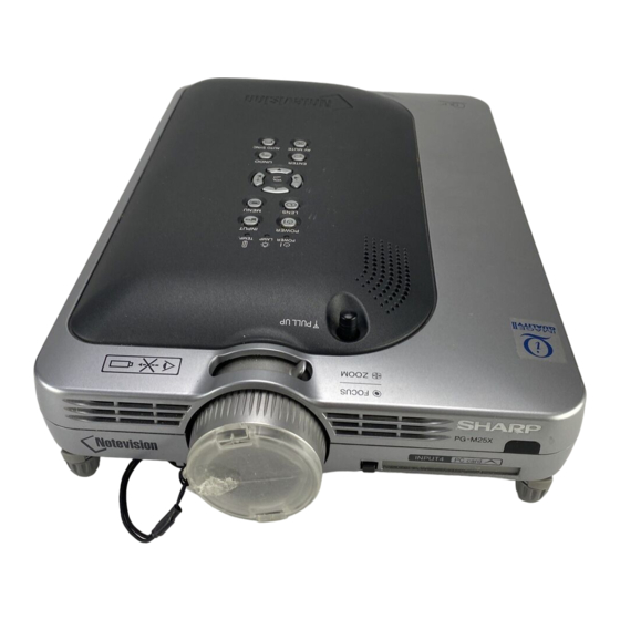
Seite 54: Projektor (Seitenansicht)
PG-M25X Projektor (Seitenansicht) INPUT 3-Anschluss FŸr den Anschluss eines VideogerŠtes. INPUT AUDIO-Anschluss Gemeinsam genutzter Audioanschluss fŸr EINGANG 1, EINGANG 2, EINGANG 3 und EINGANG 4. INPUT 1-Anschluss Schnittstelle fŸr DVI Digital-, USB-Schnittstelle Analog-DVI-RGB- und FŸr den Anschluss eines COMPONENT -Signale. Computers mittels USB- Kabel. -
Seite 55: Gyroremote-Fernbedienung
PG-M25X GyroRemote-Fernbedienung Vorderseite LED-Anzeige Leuchtet, wenn die GyroRemote- Funktionstasten 1 / 2 Fernbedienung aktiviert ist. FŸr die Angabe der POINTER-Taste Tastenzuweisung fŸr Funktion 1 und Funktion 2. Wenn diese Taste gedrŸckt INPUT-Taste gehalten wird, wird ein Pointer auf der FŸr das Umschalten zwischen den EingŠngen Bildwand angezeigt. -
Seite 56: Pin-Belegung
PG-M25X Pin-Belegung DVI Digital-/Analog-EINGANG 1-Port: 29 Pin-Anschluss • DVI-Digital-EINGANG Pin-Nr. Signal Pin-Nr. Signal • • • • • • • • • • • • • • • • • • T.M.D.S-Daten 2– Hot Plug festgestellt • • • • •... -
Seite 57: Abmessungen
PG-M25X Abmessungen Einheiten: Zoll (mm) Ansicht von hinten Ansicht von Ansicht von Ansicht von oben der Seite der Seite (223) (306,5) (303) ¿54 (219) (128) (68,7) (151,6) (wenn die Antenne (76) (38,7) (82,9) herausgezogen ist) (34,2) Ansicht von vorne ¿54 (115,5) (195) (82,5) -
Seite 58: Ausbau Wichtiger Teile
PG-M25X AUSBAU WICHTIGER TEILE 1. Ausbau der Oberabdeckung 1-1. Die Klemmenblock-Abdeckung entfernen. 1-2. Die fünf Sperrschrauben von der Oberabdeckung entfernen. 1-3. Die rechte Seite des Unterteils drücken, um den Haken zu lösen. 1-4. Die linke Seite des Unterteils drücken, um den Haken zu lösen. 1-5. -
Seite 59: Ausbau Der Betriebs-Platine
PG-M25X 3. Ausbau der Betriebs-Platine 3-1. Die zwei Sperrschrauben von der Betriebs-Platine entfernen, und dann die Platine leicht anheben. 3-2. Die Steckverbinder abtrennen. 4. Ausbau des Optikmechanismus 4-1. Die beiden Sperrschrauben von der Lampenfassung entfernen. 4-2. Die beiden Lampenfassungs-Leitungsbefestigungen anheben. 4-3. -
Seite 60: Ausbau Der Anderen Platinen
PG-M25X 5. Ausbau der anderen Platinen 5-1. Die Steckverbinder abtrennen. 5-2. Die vier Sperrschrauben von der Betriebsstrom-Platine entfernen. 5-3. Die Sperrschraube von der Vorschaltdrossel-Platineneinheit entfernen. 5-4. Die drei Sechskant-Halteschrauben von der Eingangsplatine entfernen. 5-5. Die Sperrschraube von der Klemmenblock-Abdeckung entfernen. 5-6. -
Seite 61: Ausbau Der Formatierer-Platine
PG-M25X 6. Ausbau der Formatierer-Platine 6-1. Die Steckverbinder abtrennen. 6-2. Die beiden Sperrschrauben von der Wärmesenke entfernen. 6-3. Die vier Sperrschrauben von der Rückhalteplatten-Bügel entfernen, und die Formatierer-Platine abnehmen. Hinweis: Die DMD(Digital-Mikrospiegel-Vorrichtung)-Einheit wird leicht durch statische Elektrizität beeinflusst. Beim Umgang mit diesem Gerät immer ein statikableitendes Armband tragen oder andere Maßnahmen gegen Statik treffen. - Seite 62 PG-M25X * Vorsichtsmaßregeln zur Einrichtung der DMD(Digital-Mikrospiegel-Vorrichtung)-Einheit Vor dem Anschließen der Formatierer-Platine an den Optikapparat die folgenden Schritte ausführen. Die Spannngsrang- Markierung am DMD selber prüfen. Entsprechend dieser Markierung die DIP-Schalter an der Formatier-Platine einstellen. Danach diese Platine an den Optikapparat anschließen. Falsche Einstellungen beeinträchtigen die Systemleistung. Spannungsstand-Markierung Diese Probe ist "C".
- Seite 63 PG-M25X Kurzbeschreibung des Optikapparats <Layout> Relaislinsen Stablinse Reflektor Projektionsobjektiv Lampe UV/IR-Filter Prisma Farbrad DMD-Chip Funktion Gegenstand Lichtquelle. Gleichstrombetr iebene Hochdr uck- Lampe Quecksilberdampflampe. UV/IR-Filter Zur Absorption von Ultraviolett- und Infrarotstrahlen. Dient zum Durchlassen der Lichtquelle durch den Farbfilter Farbrad und Aufspalten in die Farben R, G und B. Stablinse Dient zur Erzeugung uniformer Lichtstrahlen.
-
Seite 64: Rückstellung Des Lampen-Timers
PG-M25X RÜCKSTELLUNG DES LAMPEN-TIMERS Den Lampen-Timer nach dem Lampenaustausch zurückzustellen. Das Netzkabel anschließen. • Das Netzkabel am Netzanschluss des Projektors anschließen. Den Lampen-Timer zurückstellen. Netzanschluss • Während auf dem Projektor gleichzeitig gedrückt wird, POWER-Taste auf dem Projektor drücken. • “LAMPE 0000H” erscheint und zeigt damit Einstelltasten an, dass der Lampen-Timer zurückgestellt "... - Seite 65 Unnormal BelŸftungsšffnungen Den Projektor an einem besser blockiert. belŸfteten Ort aufstellen. Die Temperatur • • Temperatur- KŸhlventilator Den Projektor einem von Sharp im Inneren des Rot ein/ warn- beschŠdigt autorisierten HŠndler fŸr Projektoren GerŠtes ist zu Strom aus • Anzeige...
-
Seite 66: Freigabe Der Systemsperre
PG-M25X Freigabe der Systemsperre Das Gerät einschalten. Wenn die Systemsperre aktiviert wird, erscheint die System-Nullstellungsanzeige. Danach sind die folgenden Tasten in der vorgeschriebenen Reihenfolge zu betätigen. MENU → ENTER → ENTER → MENU → UNDO → UNDO → MENU Zuerst die MENU-Taste drücken, dann die verbleibenden Tasten innerhalb von 10 Sekunden betätigen. -
Seite 67: Elektrisch Einstellung
PG-M25X ELEKTRISCH EINSTELLUNG Einstellposten Einstellbedingungen Einstellverfahren Initialisierung des 1. Das Gerät einschalten (Lampe 1. Folgende Einstellungen ausführen. EEPROM leuchtet auf) und das System für SW200 drücken, um in den 15 Minuten aufwärmen lassen. Prozeßmodus einzutreten, dann S2 im SSS-Menü ausführen. Einstellung für 1. - Seite 68 PG-M25X Einstellposten Einstellbedingungen Einstellverfahren Einstellung der 1. Das interne 8-Kanal-Trennsignal 1. Den festgelegten Wert bestätigen. NTSC- zuführen. Festgelegter Wert: 59 Farbsättigung 2. Die nachfolgende Gruppe bzw. die Position wählen. Gruppe: VIDEO Posten: N-COLOR Einstellung der 1. Das PAL-Farbbalkensignal 1. Den festgelegten Wert bestätigen. PAL-Farbsättigung zuführen.
-
Seite 69: V-G1-1 Gain Und V-B1-Gain So
PG-M25X Einstellposten Einstellbedingungen Einstellverfahren Automatische 1. Das Grau-Mustersignal (50%) 1. V-G1-1 GAIN und V-B1-GAIN so Einstellung der zuführen (NTSC, Burst-Signal). einstellen, daß der x-Wert 265±3 Video- 2. Die nachfolgende Gruppe bzw. und der y-Wert 298±3 beträgt. Weißbalance die Position wählen. Gruppe: DLP Posten: V-R1-GAIN (Rot) V-B1-GAIN (Blau) - Seite 70 PG-M25X Einstellposten Einstellbedingungen Einstellverfahren Überprüfung im Das Gerät an den Projektor angeschlossenen anschließen. Sicherstellen, daß die Zustand ferngesteuerte Registrierung gut funktioniert und sich der Zeiger entsprechend bewegt. 1. Die Einstellbedingungen für jeden Bestätigung und Sicherstellen, daß keine Abweichung einzelnen Posten sind wie folgt: Neueinstellung in der Weißbalance auftritt (verglichen Für RGB-Eingang auf Posten 13-...
-
Seite 71: Einstellung Der Pc-Platine
PG-M25X Einstellposten Einstellbedingungen Einstellverfahren Leistungsprüfung Sicherstellen, daß die Gyro- der Gyro- Fernbedienung wie vorgeschrieben Fernbedienung funktioniert. Leistungsprüfung 1. Die drahtlose LAN-Karte in den 1. Sicherstellen, daß das Bild richtig für PC-Karte PC-Steckplatz einführen. übertragen werden kann. 2. Danach die Speicherkarte mit den 2. -
Seite 72: Eingabe Des Einstellprozeßmodus
PG-M25X » Eingabe des Einstellprozeßmodus Es gibt die folgenden zwei Verfahren. » Den SW2001 an der Tastenplatinen-Einheit drücken. » Die folgenden Tasten in der vorgeschriebenen Reihenfolge betätigen. AV MUTE→AV MUTE→Einstell oben→Einstell unten→ENTER→ENTER→MENU » Einstellmodus-Prozessmenü Gruppe Untergruppe Gegenstand APC-Bild einstellen R-BRIGHT G-BRIGHT B-BRIGHT AD-AUTO... - Seite 73 PG-M25X Gruppe Untergruppe Gegenstand Beispielmuster PATTERN RGB(50) CROSS FOCUS SETP COLOR CVIC einstellen CVIC-PROGRSSIVE MODE MDSW PTGSW C-TESTSW C-ILG-LY C-MOD-LY C-VE-LV CVIC-ENHANCE-VIDE ENH-PLUS ENH-MINUS CVIC-ENHANCE-HTTV ENH-PLUS ENH-MINUS CVIC-ENHANCE-RGB MODE ENH-GAIN ENH-PLUS CVIC-SCREEN CUBIC-RGB CUBIC-VEDEO CVIC-NR YNR-LEVEL YNR-K YNR-FSEL CNR-LEVEL CNR-K CNR-FSEL CNR-FILSW CVIC-PTG...
- Seite 74 PG-M25X Die neueste Version dieses Programms (USB-Seriell-Treiberprogramm) von der Homepage des SHARPs “http://172.24.145.13/tcg-qrc/prj/prj-e.asp” herunterladen. SCHRITT 1 Einrichtung für seriellen USB-Treiber (Siehe Datei "Treiberinstallationsverfahren und Rat.doc") SCHRITT 2 Den Einstellprozeßmodus anrufen, und die Untergruppe “SPECIAL” sowie den Einstellposten “USB-MODE” wählen. Den USB MODE-Wert von 0 auf 1 umstellen. (Für diese Änderung wird Eingabe eines 232C-Befehls möglich.) SCHRITT 3 Das USB-Kabel zwischen PC und Projektor anschließen.
-
Seite 75: Fehlersuchtabelle
PG-M25X FEHLERSUCHTABELLE Üerprüfen der grundlegenden Funktionen Nein Zu “Überprüfen des Netzteils” Leuchtet die POWER LED auf, weitergehen. oder blinkt sie in Rot bzw. Grün? Funktioniert das Gerät durch den Zu “Überprüfen des Sub-Microcomputers Geräteschlüssel oder die Nein und seiner zugehörigen Komponenten” Einschalttaste auf der weitergehen. - Seite 76 PG-M25X Überprüfen des Netzteils Die Anschlüsse CN702, CN704, Nein Sind die Anschlüsse des Netzteils CN7003, CN7001, CN7004 und vollst_ndig eingesteckt? CN7101 vollständig einstecken. Nein Ist die Lampentür vollständig Die Lampentür mit den Schrauben geschlossen? vollständig schließen. Funktioniert die Nein Die Sicherung zusammen mit Temperatursicherung? ihrem Kabelbaum ersetzen.
- Seite 77 PG-M25X Lampe leuchtet nicht auf (Formatiereinheit) Hat einer der Steckverbinder SC9001, SC9002, P9002 und P9003 schlechten Die Stecker vollständig einstecken. oder fehlenden Kontakt? Nein Liegt die vorgeschriebene Den Gebläseschaltkreis Nein Nein Liegt die vorgeschriebene Spannung an Stift (11) von (bei IC2101) an der Spannung an Stift (15) von P3002 an? Betriebs-Platine prüfen.
- Seite 78 PG-M25X Die Lampe leuchtet nicht auf. Den Stromkreis der Nein Dreht sich das Kühlgebläse? Gebläseschaltkreises und der Tasten/Eingangsplatine überprüfen. Den IC3101, den Motorantriebs-Schaltkreis Nein Ist der Rotationston der und ihre zugehörigen Komponenten Farbscheibe hörbar? überprüfen. Die Wellenform von SC3101 überprüfen. Normal Abnormal Die Farbscheibe...
- Seite 79 PG-M25X Überprüfen des Sub-Microcomputers und seiner zugehörigen Komponenten Nein Blinkt die POWER LED in Rot (für 2 Sekunden)? Zu “Überprüfen der PC-Schnittstelle” Liegt ein Spannungsausgangssignal weitergehen und den flexiblen Stecker von B+3,3 V an den Stiften (12) und überprüfen. (13) des CN3701 an? Kommunikationsfehler des Sub- Mikrocomputers (KEY) und des SH- Nein...
- Seite 80 PG-M25X Überprüfen des Tiefpaß-Filters Wird das Videosignal den Stiften Nein Die Stifte (4), (8) und (12) von (4), (8) und (12) des IC3851 SC3001 überprüfen. zugeführt? Normal Abnormal Die PC-Schnittstelle überprüfen. Q3854 und Q3855 Den DVI-Eingang (analog) überprüfen. überprüfen. Wird das Videosignal den Stiften Der IC3851 ist defekt.
- Seite 81 PG-M25X Überprüfen des DTV (480i- Komponenten-Signaleingang) Das 480i-Komponentensignal dem INPUT 1 zuführen. Zu “Überprüfen des INPUT 1 mit der Gerätetaste bzw. mit der Fernbedienung Tiefpaß- anwählen. Filterschaltkreises” Auf der Benutzermenü-Anzeige 480i unter den Spezialmodi weitergehen. auswählen. Bestätigung der Synchronisation. Den IC8016 Nein Wird das Y-Signal einschließlich Wird ein Bild ausgegeben?
- Seite 82 PG-M25X Überprüfen des Videoeingangs Das Farbbildsignal dem INPUT 3 zuführen. INPUT 3 mit der Gerätetaste bzw. mit der Fernbedienung anwählen. Werden 5pm-Signale Bestehen Bildstörungen? Wird ein Bild ausgegeben? (horizontal) und 10pm-Signale (vertikal) dem IC8363 der PC- Nein Nein Schnittstelle zugeführt? Nein IC8363 und IC8025 (CVIC2) Wird das Videosignal einschließlich...
- Seite 83 PG-M25X » FORMATTER Unit Abnormales Bild Abbildung (gleicht Stromausfall Andere Regenbogen) Nein Nein Zu “Lampe leuchtet nicht auf” Leuchtet die Lampe? weitergehen. Liegen an den Stiften (3), Nein Zu “Überprüfen der PC- (5) und (7) von SC9001 Platine” weitergehen. Signale an? Probleme mit IC9003, IC9006 und den zugehörigen Komponenten.
- Seite 84 PG-M25X » PC I/F Unit-1/12 Überprüfen der PC-Platine Wird das Benutzermenü angezeigt? Nein Die Bildschirmanzeige überprüfen. Den RGB-Eingang überprüfen. Den Komponenteneingang überprüfen. Den Videoeingang überprüfen. Den DVI-Digitaleingang überprüfen. Die PC-Karte überprüfen. Ende...
- Seite 85 PG-M25X » PC I/F Unit-2/12 Überprüfen der Bildschirmanzeige Wird das Benutzermenü Die Bildschirmanzeige ist normal. normalerweise durch die MENU- Taste angezeigt? Nein Das Prozeßmenü eingeben und PATTERN anwählen. Danach das COLOR-Muster wählen. Nein Die Farbe der Bildschirmanzeige Das DLP-System im Prozeß- normal? Einstellmodus einstellen.
-
Seite 86: Den Autosync-Prozeß
PG-M25X » PC I/F Unit-3/12 Überprüfen des RGB-Eingangs Das RGB-Signal (Synchronisationstyp- Analogsignal) dem INPUT 1 zuführen. INPUT 1 mit der Gerätetaste bzw. mit der Fernbedienung anwählen. Nein Zu “Bestätigen des Erscheint das Bild? Videoeingangs” weitergehen. Zu “Überprüfen des Ist das Bild gestört? Synchronisationssignals”... - Seite 87 PG-M25X » PC I/F Unit-4/12 Bestätigung des Videoeingangs “Bestätigung der Eingangssignal- Einstellung” vornehmen. Nein Nein Liegt am C8070 ein Videosignal Liegt am Anschluß C2 von P8001 vor? (DVI-Stecker) ein Signal an? Zu “Überprüfen des Defekt innerhalb des Synchronisationssignals” Signalverlaufs. Die Kondensatoren weitergehen.
- Seite 88 PG-M25X » PC I/F Unit-5/12 Überprüfen des Synchronisationssignals Liegt am Stift (11) von IC8363 ein Nein Vertikal- Synchronisationssignal Liegt am Stift (5) von IC8363 ein Nein Bestätigung der Eingangssignal- Horizontal- Synchronisationssignal Einstellung vornehmen. IC8330, IC8331 oder ihre zugehörigen Komponenten sind defekt.
- Seite 89 PG-M25X » PC I/F Unit-6/12 Überprüfen der R-, G- und B- Signale Ist der Signaltyp auf RGB Nein eingestellt? Den Signaltyp auf RGB einstellen. Den Prozeßmodus einstellen. R, G und B einzeln auf dem Mustermenü anwählen. Zu “Überprüfen von GA4 und seine zugehörigen Komponenten”...
- Seite 90 PG-M25X » PC I/F Unit-7/12 Überprüfen von GA4 und seine zugehörigen Komponenten R, G und B einzeln auf dem Mustermenü anwählen. Das Überprüfen von GA4 und der Wird das Bild korrekt in R-, G- zugehörigen Komponenten ist und B-Signalen ausgegeben? beendet.
- Seite 91 PG-M25X » PC I/F Unit-8/12 Überprüfen des Komponenteneingangs (außer 480I) Das Komponentensignal dem INPUT 1 zuführen. INPUT 1 mit der Gerätetaste bzw. mit der Fernbedienung anwählen. Nein Zu “Überprüfen des SOG- Erscheint das Bild? Schaltkreises” weitergehen. Ist die Farbe normal? Nein Nein Ist der Signaltyp auf die...
- Seite 92 PG-M25X » PC I/F Unit-9/12 Überprüfen des SOG-Schaltkreises Den Stift (2) von IC8365 mit dem Oszilloskop überprüfen. Wird das Farbbildsignal mit dem Der SOG-Schaltkreis ist normal. korrekten Timing reproduziert? Ende. Nein C8070 mit dem Oszilloskop überprüfen. Nein Liegt ein Y-Signal (einschl. Zu “Bestätigung der Eingangssignal-Einstellung”...
- Seite 93 PG-M25X » PC I/F Unit-10/12 Überprüfen des Videoeingangs Das Farbbildsignal dem INPUT 3 zuführen. INPUT 1 mit der Gerätetaste bzw. mit der Fernbedienung anwählen. Zu “Überprüfen des Video- Nein Erscheint das Bild? Synchronsignals” weitergehen. Bestehen irgendwelche Bildstörungen? Nein Zu “Überprüfen des Video- Die Prozeß-Einstellung Synchronsignals”...
- Seite 94 PG-M25X » PC I/F Unit-11/12 Überprüfen des Video- Synchronsignals Den Stift (10) von IC8363 mit dem Oszilloskop überprüfen. (Überprüfen des Vertikal-Synchronsignals) Nein Ist das Vertikal-Synchronsignal normal? Den Stift (6) von IC8363 mit dem Oszilloskop überprüfen. (Überprüfen des Vertikal- Synchronsignals) Nein Zu “Bestätigung der Ist das Horizontal-Synchronsignal Eingangssignal-Einstellung”...
- Seite 95 PG-M25X » PC I/F Unit-12/12 Überprüfen des DVI-Digitaleingangs Das DVI-Digitalsignal dem INPUT 1 zuführen. INPUT 1 als Eingang wählen. Nein Erscheint das Bild? Nein Treten irgendwelche Bildstörungen auf? Nein Der IC8298 und seine zugehörigen Ist die Farbe normal? Komponenten sind defekt. Der DVI-Eingang ist normal.
-
Seite 96: Chassis Layout
PG-M25X CHASSIS LAYOUT/CHASSIS-ANORDNUNG... - Seite 97 PG-M25X...
-
Seite 100: Overall Wiring Diagram
PG-M25X OVERALL WIRING DIAGRAM/GESAMTSCHALTPLAN... - Seite 101 PG-M25X...
-
Seite 102: Description Of Schematic Diagram
PG-M25X DESCRIPTION OF SCHEMATIC BESCHREIBUNG DES DIAGRAM SCHEMATISCHEN SCHALTPLANS VOLTAGE MEASUREMENT CONDITION: SPANNUNGSMESSUNGEN: 1. Spannungen an den Prüfpunkten werden bei einer 1. Voltages at test points are measured at the supply Netzspannung von 230V gemessen, Signale werden voltage of AC 230V. Signals are fed by a colour bar für die Wartung mit einem Farbbalken-Signal signal generator for servicing purpose and the above generator zugeführt, und Spannungen werden mit... - Seite 103 PG-M25X WAVEFORMS/WELLENFORMEN 1 SC3101 1-pin 2 SC3101 3-pin 3 P9002 1-pin 4 P9003 2-pin (INPUT CWCTR) (INPUT CWY2) (FORMAT LAMPEN) (FORMAT CWINDEX) H : 200µ sec/div H : 200µ sec/div H : 2m sec/div H : 2m sec/div V : 6.90V/div V : 6.90V/div V : 1.64V/div V : 1.64V/div...
-
Seite 104: Ë Formatter Unit-1/5 / Formatierer Einheit-1
PG-M25X Ë FORMATTER UNIT-1/5 / FORMATIERER EINHEIT-1/5... - Seite 105 PG-M25X...
-
Seite 106: Ë Formatter Unit-2/5 / Formatierer Einheit-2
PG-M25X Ë FORMATTER UNIT-2/5 / FORMATIERER EINHEIT-2/5... - Seite 107 PG-M25X...
-
Seite 108: Ë Formatter Unit-3/5 / Formatierer Einheit-3
PG-M25X Ë FORMATTER UNIT-3/5 / FORMATIERER EINHEIT-3/5... - Seite 109 PG-M25X...
-
Seite 110: Ë Formatter Unit-4/5 / Formatierer Einheit-4
PG-M25X Ë FORMATTER UNIT-4/5 / FORMATIERER EINHEIT-4/5... - Seite 111 PG-M25X...
-
Seite 112: Ë Formatter Unit-5/5 / Formatierer Einheit-5
PG-M25X Ë FORMATTER UNIT-5/5 / FORMATIERER EINHEIT-5/5... - Seite 113 PG-M25X...
-
Seite 114: Ë Input Unit-1/5 / Eingangseinheit-1
PG-M25X Ë INPUT UNIT-1/5 / EINGANGSEINHEIT-1/5... - Seite 115 PG-M25X...
-
Seite 116: Ë Input Unit-2/5 / Eingangseinheit-2
PG-M25X Ë INPUT UNIT-2/5 / EINGANGSEINHEIT-2/5... - Seite 117 PG-M25X...
-
Seite 118: Ë Input Unit-3/5 / Eingangseinheit-3
PG-M25X Ë INPUT UNIT-3/5 / EINGANGSEINHEIT-3/5... - Seite 119 PG-M25X...
-
Seite 120: Ë Input Unit-4/5 / Eingangseinheit-4
PG-M25X Ë INPUT UNIT-4/5 / EINGANGSEINHEIT-4/5... - Seite 121 PG-M25X...
-
Seite 122: Ë Input Unit-5/5 / Eingangseinheit-5
PG-M25X Ë INPUT UNIT-5/5 / EINGANGSEINHEIT-5/5... - Seite 123 PG-M25X...
-
Seite 124: Ë Key Unit-1/3 / Schlüsseleinheit-1
PG-M25X Ë KEY UNIT-1/3 / SCHLÜSSELEINHEIT-1/3... - Seite 125 PG-M25X...
-
Seite 126: Ë Key Unit-2/3 / Schlüsseleinheit-2
PG-M25X Ë KEY UNIT-2/3 / SCHLÜSSELEINHEIT-2/3... - Seite 127 PG-M25X...
-
Seite 128: Ë Key Unit-3/3 / Schlüsseleinheit-3
PG-M25X Ë KEY UNIT-3/3 / SCHLÜSSELEINHEIT-3/3... - Seite 129 PG-M25X...
- Seite 130 PG-M25X Ë GYRO UNIT...
- Seite 131 PG-M25X...
- Seite 132 PG-M25X Ë GYRO SUB UNIT...
- Seite 133 PG-M25X...
-
Seite 134: Ë Power Unit/Netzeinheit
PG-M25X Ë POWER UNIT/NETZEINHEIT... - Seite 135 PG-M25X...
-
Seite 136: Ë Pfc Unit/Pfc-Einheit
PG-M25X Ë PFC UNIT/PFC-EINHEIT... - Seite 137 PG-M25X...
- Seite 138 PG-M25X Ë PC I/F UNIT-1/7 / PC-I/F-EINHEIT-1/7...
- Seite 139 PG-M25X...
- Seite 140 PG-M25X Ë PC I/F UNIT-2/7 / PC-I/F-EINHEIT-2/7...
- Seite 141 PG-M25X...
- Seite 142 PG-M25X Ë PC I/F UNIT-3/7 / PC-I/F-EINHEIT-3/7...
- Seite 143 PG-M25X...
- Seite 144 PG-M25X Ë PC I/F UNIT-4/7 / PC-I/F-EINHEIT-4/7...
- Seite 145 PG-M25X...
- Seite 146 PG-M25X Ë PC I/F UNIT-5/7 / PC-I/F-EINHEIT-5/7...
- Seite 147 PG-M25X...
- Seite 148 PG-M25X Ë PC I/F UNIT-6/7 / PC-I/F-EINHEIT-6/7...
- Seite 149 PG-M25X...
- Seite 150 PG-M25X Ë PC I/F UNIT-7/7 / PC-I/F-EINHEIT-7/7...
- Seite 151 PG-M25X...
-
Seite 152: Printed Wiring Board Assemblies
PG-M25X PRINTED WIRING ASSEMBLIES/ LEITERPLTTENEINHEITEN FORMATTER Unit (Side-A) FORMATIERER Einheit (Seite-A) INPUT Unit (Side-A) EINGANGS Einheit (Seite-A) - Seite 153 PG-M25X FORMATTER Unit (Side-B) FORMATIERER Einheit (Seite-B) INPUT Unit (Side-B) EINGANGS Einheit (Seite-B)
- Seite 154 PG-M25X KEY Unit (Side-A) SCHLÜSSEL Einheit (Seite-A) PFC Unit (Side-A) PFC-Einheit (Seite-A)
- Seite 155 PG-M25X KEY Unit (Side-B) SCHLÜSSEL Einheit (Seite-B) PFC Unit (Side-B) PFC-Einheit (Seite-B)
- Seite 156 PG-M25X PC I/F Unit (Side-A) PC-I/F Einheit (Seite-A)
- Seite 157 PG-M25X PC I/F Unit (Side-B) PC-I/F Einheit (Seite-B)
-
Seite 158: Netz Einheit (Bestückugsseite)
PG-M25X POWER Unit (Component Side) NETZ Einheit (Bestückugsseite) (Side-A) (Side-B) GYRO SUB Unit GYRO-HILFS-Einheit (Side-A) (Side-B) GYRO Unit GYRO-Einheit... -
Seite 159: Printed Wiring Board Assemblies
Contact your nearest SHARP Parts Distributor. For location of SHARP Parts Distributor, 5. KODE 6. QUANTITÄT Please call Toll-Free; 1-800-BE-SHARP in CANADA: Contact SHARP Electronics of Canada Limited Phone (416) 890-2100. MARK: SPARE PARTS-DELIVERY SECTION MARKIERUNG : ERSATZTEILE-LIEFERUNG Ref. No. -
Seite 174: Ë Cabinet And Mechanical Parts
PG-M25X CABINET AND MECHANICAL PARTS/ GEHÄUSE UND MACHANISCHE BAUTEILE 1-1-7 1-1-5 1-1-1 1-1-8 1-1-9 1-1-2 1-1-4 1-1-3 1-1-10 1-1-6 2-3-3 2-2-9 2-3-1 2-3-2 4-1-2 2-2-5 2-2-10 4-1-1 2-2-8 2-2-11 2-2-1 2-1-1 2-2-10 2-1-5 2-2-12 2-2-7 2-1-2 2-2-2 2-2-6 2-2-10 2-1-4 2-1-3 2-2-4... - Seite 177 PG-M25X OPTICS MECHANISM PARTS TEILE FÜR OPTIKMECHANISMUS 7-1-32 7-1-16 7-1-10 7-1-10 7-1-36 7-1-6 7-1-18 7-1-15 7-1-7 7-1-9 7-1-17 7-1-13 7-1-18 7-1-27 7-1-35 7-1-11 7-1-14 7-1-8 7-1-37 7-1-25 7-1-31 7-1-19 7-1-24 7-1-12 7-1-29 7-1-23 7-1-20 7-1-21 7-1-30 7-1-2 7-1-5 7-1-22 7-1-29 7-1-26 7-1-28 7-1-27...
- Seite 180 6. QUANTITY in USA: Contact your nearest SHARP Parts Distributor. For location of SHARP Parts Distributor, Please call Toll-Free; 1-800-BE-SHARP in CANADA: Contact SHARP Electronics of Canada Limited Phone (416) 890-2100. MARK: SPARE PARTS-DELIVERY SECTION MARKIERUNG : ERSATZTEILE-LIEFERUNG Ref. No.
- Seite 182 PG-M25X COPYRIGHT © 2002 BY SHARP CORPORATION ALL RIGHTS RESERVED. No part of this publication may be reproduced, stored in a retrieval system, or transmitted in any form or by any means, electronic, mechanical, photocopying, recording, or otherwise, without prior written permission of the publisher.