Christopeit Sport TM 2000S Bedienungsanleitung

Verwandte Anleitungen für Christopeit Sport TM 2000S


Inhaltszusammenfassung für Christopeit Sport TM 2000S
- Seite 1 Heimsport-Trainingsgerät Elektrisches Laufband 1574 Montage- und Bedienungsanleitung für Bestell-Nr. 1574 Assembly and exercise instructions for Order No.
-
Seite 2: Wichtige Empfehlungen Und Sicherheitshinweise
Inhaltsübersicht Contents Page 1. Wichtige Empfehlungen und Sicherheitshinweise Seite 2. Einzelteileübersicht Seite 3 - 4 3. Stückliste-Ersatzteilliste-Techn. Daten Seite 5 - 6 4. Montageanleitung mit Explosionsdarstellungen Seite 7 - 9 5. Reinigung, Wartung und Lagerung Seite 10 6. Computeranleitung, Störungsbeseitigung Seite 11 - 17 7. -
Seite 5: Stückliste - Ersatzteilliste
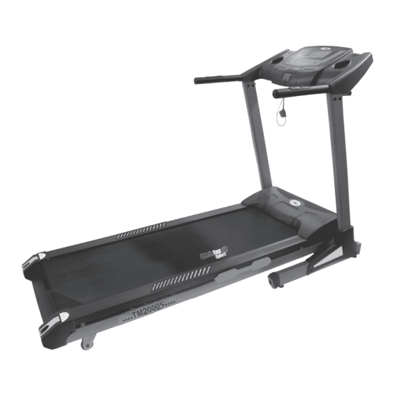
Stückliste - Ersatzteilliste Stellmaße: ca. L 192 x B 82 x H 129 cm Stellmaße hochgeklappt: ca. L 80 x B 82 x H 162 cm TM 2000S Best.-Nr. 1574 Trainingsplatzbedarf: ca. 6m² Technische Daten: Stand: 01. 10. 2015 Elektrisches Laufband Nach Öffnen der Verpackung bitte kontrollieren, ob alle Teile ent- • Motor Dauerleistung 2 PS (1,5Kw), maximale Motorleistung 3 PS (2,2Kw) • Geschwindigkeit: 1 km/h bis 20 km/h (in 0,1 km/h Schritten einstellbar) sprechend der nachfolgenden Stückliste vorhanden sind. Ist dies • 4 manuelle Programme mit Vorgabe von Zeit, Entfernung, Kalorien und... - Seite 6 Abbildungs- Bezeichnung Abmessung Menge Montiert an ET-Nummer Stück Abbildungs Nr. Hintere Rolle 33-1574-09-SI Rechteckstopfen 36-1574-08-BT Rechteckstopfen 36-1574-09-BT Rundstopfen 36-1574-10-BT Stützrohrverkleidung links 36-1574-04-BT Stützrohrverkleidung rechts 36-1574-05-BT Verkleidung 36-1574-01-BT Abdeckung unten 36-1574-02-BT Abdeckung hinten 36-1574-06-BT Rollenabdeckung 36-1574-07-BT Distanzstück 36-1574-11-BT Trittleistenaufnahme 36-1241-36-BT Schraubschutz 36-1574-12-BT Hauptschalter 36-1241-17-BT...
- Seite 7 Montageanleitung Bevor Sie mit der Montage beginnen, unbedingt unsere Emp- fehlungen und Sicherheitshinweise beachten! Entnehmen Sie alle Einzelteile aus dem Karton und legen Sie den vormontierten Teil des Laufbandes (5) mit Unterstützung einer zweiten Person auf den Boden. Kontrollieren Sie grob die Vollzäh- ligkeit anhand der Montageschritte.
- Seite 8 Schritt 3: 1. Montieren Sie Stützrohrverkleidungen links und rechts (38+39) über die Verschraubungen von Grundrahmen (1) und Stütz- rohren (2+3) mittels der Schrauben (18). Schritt 4: Kontrolle und Inbetriebnahme 1. Alle Verschraubungen und Steckverbindungen auf ordnungs- gemäße Montage und Funktion prüfen. 2.
-
Seite 9: Ein- / Ausklappen Und Transportieren Des Laufbandes
Ein- / Ausklappen und transportieren 2. Platz sparend einklappen und Standortwechsel: Heben Sie den Laufrahmen an Position „A“ an und klappen des Laufbandes Sie das Laufband durch Anheben hochkant zusammen bis der Sicherungsknopf (83) einrastet. Durch vollständiges Einklappen 1. Zum Training ausklappen: werden automatisch die Transportrollen vorne in Funktion ge- Halten Sie das Laufband an Position „A“... -
Seite 10: Anmerkungen Zur Wartung Und Einstellung
Anmerkungen zur Wartung und Einstellung 1. Pflegen der Lauffläche: Damit das Laufband dauerhaft leicht und gut läuft, sollte immer nach 50 Betriebsstunden die Unterseite der Lauffläche, welche auf dem Gleitbrett liegt auf Ihre Gleitfähigkeit geprüft werden und ggf. mit Siliconspay (Kein Schmierstoff auf ÖL- oder Petroleum Basisverwenden) nachbehandelt werden. -
Seite 11: Computerbeschreibung
Computerbeschreibung „-“ –Taste: Drücken dieser Taste verringert die Geschwindigkeit während des Betriebs des Laufbandes. Bei Stillstand können Eingabewerte ver- mindert werden. Diese Tastenfunktion befindet sich auch an den Pulsgriffen. „+“ – Steigungstaste: Drücken dieser Taste erhöht die Steigung während des Betriebes des Laufbandes. - Seite 12 Sicherungs- Clip Um das Programm zu unterbrechen drücken Sie erneut die Start/ Stop-Taste. Der Sicherungsclip dient zu Absicherung in Notfällen. Er muss auf dem Computer aufliegen um Eingaben zu machen und das Lauf- Individuelle Benutzerprogramme U1+U2: band zu starten. Es gibt 2 Benutzerprogramme U1 und U2 die individuell mit Ge- Legen Sie den Sicherungs-Clip (59) bei jedem Training an.
- Seite 36 Service / Hersteller Bei Reklamationen, notwendigen Ersatzteilbestellungen oder © by Top-Sports Gilles GmbH Reparaturen wenden Sie sich bitte an unsere Service Abteilung. D-42551 Velbert (Germany) Service: Top-Sports Gilles GmbH Tel.: +49 (0)2051/6067-0 Friedrichstrasse 55 info@christopeit-sport.com Fax: +49 (0)2051/6067-44 D - 42551 Velbert http://www.christopeit-sport.com...