Exsys EX-644 Bedienungsanleitung
Quicklinks
EX
EX-
EX
-
-
6440 / 6450
6440 / 6450
6440 / 6450
JUMPER SETTING & CONNECTORS:
J5:
Pin
Signal Name
2 4 6
1
+12VDC Bus Power
2
GND
1 3 5
3
TPB-
JP2:
JP2
Serial EE-PROM write protected No jumper (default)
JP2
Serial EE-PROM not write protected jumper set (do not use this setting)
HARDWARE INSTALLATION :
If you are ready with the jumper settings for the card, please proceed with the following
installation instructions. Because the designs of computers are different, only general
installation instructions are given. Please refer your computer's reference manual whenever
in doubt.
1. Turn off the power to your computer and any other connected peripherals.
2. Remove the mounting screws located at the rear and/or sides panels of your Comput-
er and gently slide the cover off.
3. If necessary please install now the external power supply to the card like shown at JP1
& J4 above.
4. Locate an available & correct expansion slot ( see compatibility at technical infor-
mation above) and remove its covers from the rear panel of your computer.
5. Align the card with the expansion slot, and then gently but firmly, insert the card. Make
sure the card is seated and oriented correctly.
6. Then connect the card with a screw to the rear panel of the computer.
7. Gently replace your computer's cover and the mounting screws.
DRIVER INSTALLATION :
Windows ME
The drivers are already integrated in Windows and the card will be installed automatical-
ly.
CHECK INSTALLED DRIVER:
Open the >Device manager< . Now you should see at "IEEE1394 Devices" the following
new entry: <Texas Instruments OHCI conform IEEE1394 Hostcontroller>.
If you see this or a similar information the card is installed correctly.
Windows 2000 XP & Server200x
The drivers are already integrated in Windows and the EX-6440 / 6450 will be installed
automatically.
CHECK INSTALLED DRIVER:
Open the >Device manager< . Now you should see at "IEEE1394 Devices" the following
new entry: <Texas Instruments OHCI conform IEEE1394 Hostcontroller>.
If you see this or a similar information the card is installed correctly.
Windows Vista/ 7/ 8
The drivers are already integrated in Windows and the card will be installed automatical-
ly.
CHECK INSTALLED DRIVER:
Open the >Device manager< . Now you should see at "IEEE1394 Devices" the following
new entry: <Texas Instruments OHCI conform IEEE1394 Hostcontroller>.
If you see this or a similar information the card is installed correctly.
5
English
English
English
EX
EX-
EX
-
-
6440 / 6450
6440 / 6450
6440 / 6450
DRIVER INSTALLATION :
MAC:
Pin
Signal Name
The drivers are already integrated in MAC OS and the card will be installed automatical-
4
TPB+
ly. Only MacOS 8.6 do need a update before the card can be used. You can download
5
TPA-
the update on the MacOS homepage (e.g. FireWire Support 2.8.x)
6
TPA+
In doubt please refer to the installation manual from your MAC OS version!
LINUX:
Because each individual distribution and kernel version of Linux is different, sadly we
cant provide a installation instruction here. Please refer to the installation manual for
IEEE1394 ports from your Linux version !
English
English
English
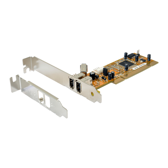
AUFBAU :
J1: J3 oder J5
1x 1394a 9 Pin Buchse
Wird mit dem externen
Port 2 J1 und 6 Pin
Steckerleiste J5 geteilt
J1: Port 2
J2: Port 1
BESCHREIBUNG & TECHNISCHE DATEN :
Die EX-6440 / 6450 ist eine Firewire 1394a PCI Karte. Sie ist mit 2 externen und 1
geteiltem internen Port ausgestattet. Sie unterstützt den PCI Bus mit 5V und 3,3 Volt. In
Verbindung mit dem schnellen Texas Instruments Chip gewährleistet die EX-6440 /
6450 eine sichere Datenübertragung und exzellente Performance von bis zu 400Mbit
pro Sekunde! Es ist nicht möglich die I/O Adressen und Interrupts manuell einzustellen,
da die Einstellungen der Karte vom System (BIOS) und beim Installieren des Betriebs-
systems automatisch vorgenommen werden. Sie hat zusätzlich einen Internen 6 Pin
Anschluss (J5) für den Anschluss von Frontpanel Geräten. Bei der EX-6440 handelt es
sich um eine LowProfile Karte mit 8cm Bügel für schmale PC Gehäuse.
Kompatibilität:
Betriebssysteme:
Anschlüsse:
Lieferumfang:
Zertifikate:
JUMPER EINSTELLUNG & ANSCHLÜSSE:
JP1:
J4:
J1-J3:
6
Bedienungsanleitung
Bedienungsanleitung
Vers. 3.3 / 01.03.13
J4
Anschluss für Stecker
vom PC-Netzteil
PCI & PCI-X 32Bit, 5V & 3,3 Volt, 33MHz
WinME/ 2000/ XP/ Vista/ 7/ 8/ Server 200x/ MAC/Linux (vom OS)
3 x 6 Pin IEEE1394a Buchse ,1 x 6 Pin block, 1 x 4Pin Strom
EX-6440 bzw. 6450 , Anleitung
CE CE CE CE
/ FCC / RoHS / WEEE
DE97424562 / WHQL
PCI = Strom vom PCI BUS (Werkseinstellung)
AUX = Strom vom PC-Netzteil des Rechners
PCI
(Zur Entlastung des Mainboards und zur stabilen Stromversorgung bei
AUX
Verwendung von Endgeräten mit hohem Stromverbrauch).
Anschluss J4 muss dann mit dem PC-Netzteil verbunden werden!
Wenn JP1 auf AUX gestellt ist muss J4 mit dem Stromanschluss vom
PC Netzteil verbunden werden! Bitte auf die richtige Polarität achten!
Achtung! Stecker nie bei eingeschaltetem PC ein oder ausstecken!
1394 6 Pin Firewire Buchse:
2 4 6
Pin
Signal
Pin
1
Power
2
GND
3
TPB-
1 3 5
1
JP1
Stromquelle wählen
PCI oder AUX
JP2:
EEPROM Jumper
TI Chipset
Signal
4
TPB+
5
TPA-
6
TPA+

Verwandte Anleitungen für Exsys EX-644


Inhaltszusammenfassung für Exsys EX-644
- Seite 1 6440 / 6450 6440 / 6450 6440 / 6450 English English English 6440 / 6450 6440 / 6450 6440 / 6450 English English English JUMPER SETTING & CONNECTORS: DRIVER INSTALLATION : MAC: Bedienungsanleitung Bedienungsanleitung Signal Name Signal Name The drivers are already integrated in MAC OS and the card will be installed automatical- 2 4 6 +12VDC Bus Power TPB+...
- Seite 2 6440 / 6450 6440 / 6450 6440 / 6450 Deutsch Deutsch Deutsch 6440 / 6450 6440 / 6450 6440 / 6450 Deutsch Deutsch Deutsch JUMPER EINSTELLUNG & ANSCHLÜSSE: TREIBER INSTALLATION : User Manual User Manual Signal Name Signal Name Sie benötigen keine Treiber, da diese im Mac OS bereits integriert sind und die Karte 2 4 6 +12VDC Bus Power TPB+...