Inhaltsverzeichnis
Werbung
Quicklinks
Pos: 2 /Dokumentation allgemein/Einband/Einband Handbuch - Deckblatt ohne Variantenfeld (Standard) @ 9\mod_1285229289866_0.doc @ 64941 @ @ 1
Manual
WAGO-I/O-SYSTEM 753
®
LON
FTT Module
753-648
V1.0.0
Pos: 3 /Alle Serien (Allgemeine Module)/Hinweise zur Dokumentation/Impressum für Standardhandbücher - allg. Angaben, Anschriften, Telefonnummern und E-Mail-Adressen @ 3\mod_1219151118203_21.doc @ 21060 @ @ 1
Werbung
Inhaltsverzeichnis

Verwandte Anleitungen für WAGO LON FTT 753-648


Inhaltszusammenfassung für WAGO LON FTT 753-648
- Seite 1 Pos: 2 /Dokumentation allgemein/Einband/Einband Handbuch - Deckblatt ohne Variantenfeld (Standard) @ 9\mod_1285229289866_0.doc @ 64941 @ @ 1 Manual WAGO-I/O-SYSTEM 753 ® FTT Module 753-648 V1.0.0 Pos: 3 /Alle Serien (Allgemeine Module)/Hinweise zur Dokumentation/Impressum für Standardhandbücher - allg. Angaben, Anschriften, Telefonnummern und E-Mail-Adressen @ 3\mod_1219151118203_21.doc @ 21060 @ @ 1...
- Seite 2 WAGO-I/O-SYSTEM 753 ® 753-648 LON FTT Module © 2012 by WAGO Kontakttechnik GmbH & Co. KG All rights reserved. WAGO Kontakttechnik GmbH & Co. KG Hansastraße 27 D-32423 Minden Phone: +49 (0) 571/8 87 – 0 Fax: +49 (0) 571/8 87 – 1 69 E-Mail: info@wago.com...
-
Seite 3: Inhaltsverzeichnis
WAGO-I/O-SYSTEM 753 Table of Contents ® 753-648 LON FTT Module Pos: 5 /Dokumentation allgemein/Verzeichnisse/Inhaltsverzeichnis - ohne Gliederung - und Verzeichnis @ 3\mod_1219151230875_21.doc @ 21063 @ @ 1 Table of Contents Notes about this Documentation..............5 Validity of this Documentation..............5 Copyright.................... - Seite 4 Table of Contents WAGO-I/O-SYSTEM 753 ® 753-648 LON FTT Module Commissioning ................... 35 Preparation ....................35 ® Creating a Project and Launching the LON Configurator ....36 Note about Offline Configurations............37 Diagnostics ....................38 Use in Hazardous Environments .............. 39 Marking Configuration Examples............
-
Seite 5: Notes About This Documentation
Care must also be taken to ensure that any supplement to these instructions are included, if applicable. Pos: 9 /Serie 750 (WAGO-I/O-SYSTEM)/Hinweise zur Dokumentation/Gültigkeitsbereich Dokumentation Busklemme 750-xxxx, ohne Variantenangabe @ 4\mod_1237986650812_21.doc @ 29020 @ 2 @ 1 Validity of this Documentation This documentation is only applicable to the I/O module 753-648 (LON FTT Module) of the WAGO-I/O-SYSTEM 750 series. -
Seite 6: Symbols
Notes about this Documentation WAGO-I/O-SYSTEM 753 ® 753-648 LON FTT Module Pos: 11.3 /Alle Serien (Allgemeine Module)/Überschriften für alle Serien/Hinweis zur Dokumentation/Symbole - Überschrift 2 @ 13\mod_1351068042408_21.doc @ 105270 @ 2 @ 1 Symbols Pos: 11.4.1 /Alle Serien (Allgemeine Module)/Wichtige Erläuterungen/Sicherheits- und sonstige Hinweise/Gefahr/Gefahr: _Warnung vor Personenschäden allgemein_ - Erläuterung @ 13\mod_1343309450020_21.doc @ 101029 @ @ 1... - Seite 7 WAGO-I/O-SYSTEM 753 Notes about this Documentation ® 753-648 LON FTT Module Additional Information: Refers to additional information which is not an integral part of this documentation (e.g., the Internet). Pos: 11.5 /Dokumentation allgemein/Gliederungselemente/---Seitenwechsel--- @ 3\mod_1221108045078_0.doc @ 21810 @ @ 1 Manual V1.0.0...
-
Seite 8: Number Notation
Notes about this Documentation WAGO-I/O-SYSTEM 753 ® 753-648 LON FTT Module Pos: 11.6 /Alle Serien (Allgemeine Module)/Hinweise zur Dokumentation/Zahlensysteme @ 3\mod_1221059454015_21.doc @ 21711 @ 2 @ 1 Number Notation Table 1: Number Notation Number code Example Note Decimal Normal notation... -
Seite 9: Important Notes
® The descriptions below require knowledge in the configuration of LON network components. Pos: 14.6 /Serie 750 (WAGO-I/O-SYSTEM)/Wichtige Erläuterungen/Bestimmungsgemäße Verwendung 750-xxxx @ 3\mod_1224064151234_21.doc @ 24070 @ 3 @ 1 2.1.3 Use of the 750 Series in Compliance with Underlying Provisions... -
Seite 10: Technical Condition Of Specified Devices
The components to be supplied Ex Works, are equipped with hardware and software configurations, which meet the individual application requirements. WAGO Kontakttechnik GmbH & Co. KG will be exempted from any liability in case of changes in hardware or software as well as to non-compliant usage of components. -
Seite 11: Safety Advice (Precautions)
All power sources to the device shall be switched off prior to performing any installation, repair or maintenance work. Pos: 14.11.2 /Serie 750 (WAGO-I/O-SYSTEM)/Wichtige Erläuterungen/Sicherheitshinweise/Gefahr/Gefahr: Einbau 0750-xxxx nur in Gehäusen, Schränken oder elektrischen Betriebsräumen! @ 6\mod_1260180556692_21.doc @ 46731 @ @ 1 Installation only in appropriate housings, cabinets or in electrical operation rooms! The WAGO-I/O-SYSTEM 750 and its components are an open system. - Seite 12 Important Notes WAGO-I/O-SYSTEM 753 ® 753-648 LON FTT Module Do not use any contact spray! Do not use any contact spray. The spray may impair contact area functionality in connection with contamination. Pos: 14.12.5 /Alle Serien (Allgemeine Module)/Wichtige Erläuterungen/Sicherheits- und sonstige Hinweise/Achtung/Achtung: Verpolung vermeiden! @ 6\mod_1260184045744_21.doc @ 46767 @ @ 1...
-
Seite 13: Requirements
Table 5: Optional software Components Source WAGO-I/O-CHECK WAGO (759-302) WAGO ETHERNET Settings WAGO (free download at: www.wago.com) Pos: 18.6 /Alle Serien (Allgemeine Module)/Überschriften für alle Serien/Wichtige Erläuterungen/WAGO-I/O-SYSTEM - Überschrift 3 @ 13\mod_1342779422584_21.doc @ 100660 @ 3 @ 1 Manual V1.0.0... -
Seite 14: Wago-I/O-System
® 753-648 LON FTT Module 2.3.3 WAGO-I/O-SYSTEM Pos: 18.7 /Serie 759 (WAGO-Software)/LON-Configurator/Tabelle: Erforderliche Komponenten des WAGO-I/O-SYSTEMs (753-0648) @ 12\mod_1339753832292_21.doc @ 97779 @ @ 1 Table 6: Required Components of the WAGO-I/O-SYSTEM Components Source (item No.) Fieldbus controller/PLC WAGO (750-830, example) WAGO-I/O-SYSTEM 750 (e.g. -
Seite 15: Device Description
Pos: 20 /Alle Serien (Allgemeine Module)/Überschriften für alle Serien/Gerätebeschreibung/Gerätebeschreibung - Überschrift 1 @ 3\mod_1233756084656_21.doc @ 27096 @ 1 @ 1 Device Description Pos: 21.1 /Serie 753 (WAGO-I/O-SYSTEM)/Gerätebeschreibung/Beschreibung/753-0648/Gerätespezifische Hinweise: Anzahl Klemmen anwendungsabhängig und Strategien beachten! @ 12\mod_1339579462370_21.doc @ 97143 @ 2 @ 1 Device-specific Information ®... -
Seite 16: General Description
Device Description WAGO-I/O-SYSTEM 753 ® 753-648 LON FTT Module General Description Pos: 21.3 /Serie 753 (WAGO-I/O-SYSTEM)/Gerätebeschreibung/Beschreibung/753-0648/Busklemmenbeschreibung 753-0648 @ 12\mod_1339429001116_21.doc @ 96856 @ @ 1 ® ® Die LON-FTT-Klemme ... The LON FTT module is used to connect a LON network to a WAGO fieldbus node with PLCs (programmable fieldbus controllers) and 750/753 Series I/O modules. - Seite 17 ® In general, LON guidelines must be adhered to for network installation. The WAGO-I/O-PRO software is used to program the fieldbus nodes. For implementation of complex control applications, a comprehensive IEC-61131-3 library with simple modules is available. ® The LON configurator integrated in the WAGO-I/O-PRO makes easy setup and ®...
-
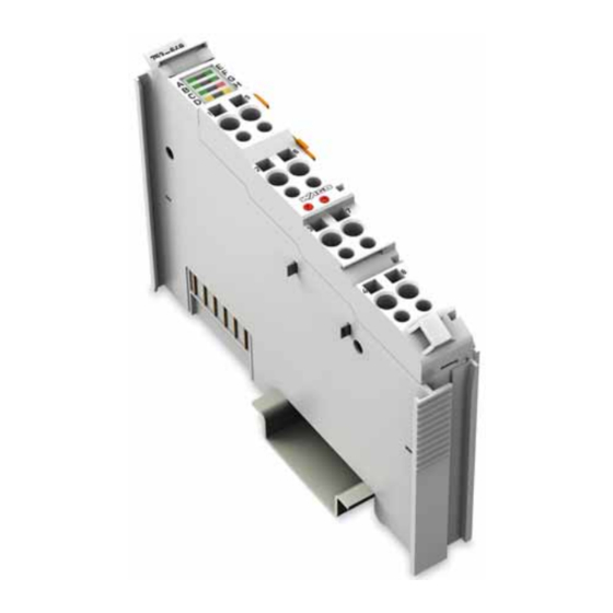
Seite 18: View
Pos: 23 /Alle Serien (Allgemeine Module)/Überschriften für alle Serien/Gerätebeschreibung/Ansicht - Überschrift 2 @ 4\mod_1240984217343_21.doc @ 31958 @ 2 @ 1 View Pos: 24 /Serie 753 (WAGO-I/O-SYSTEM)/Gerätebeschreibung/Ansicht/Sonderklemmen/Ansicht 753-0648 @ 12\mod_1337061610922_21.doc @ 94954 @ @ 1 Figure 2: View Table 7: Legend for „View“ figure Pos. -
Seite 19: Connectors
Do not place the I/O modules on the gold spring contacts in order to avoid soiling or scratching! Pos: 28.3 /Serie 750 (WAGO-I/O-SYSTEM)/Wichtige Erläuterungen/Sicherheitshinweise/Achtung/Achtung: ESD - Auf gute Erdung der Umgebung achten! @ 7\mod_1266318538667_21.doc @ 50708 @ @ 1 Ensure that the environment is well grounded! The modules are equipped with electronic components that may be destroyed by electrostatic discharge. -
Seite 20: Power Contacts/Field Supply
Figure 4: Power jumper contacts Pos: 32 /Serie 750 (WAGO-I/O-SYSTEM)/Wichtige Erläuterungen/Sicherheitshinweise/Achtung/Achtung: Maximaler Strom Leistungskontakte 10 A @ 3\mod_1226499143500_21.doc @ 25029 @ @ 1 Do not exceed maximum current via power contacts! The maximum current to flow through the power contacts is 10 A. -
Seite 21: Cage Clamp ® Connections
753-648 LON FTT Module ® 3.4.3 CAGE CLAMP Connections Pos: 34 /Serie 753 (WAGO-I/O-SYSTEM)/Gerätebeschreibung/Anschlüsse/Sonderklemmen/Anschlüsse 753-0648 @ 12\mod_1337863537392_21.doc @ 95539 @ @ 1 Table 9: Connections Connection Function Pos: 35 /Dokumentation allgemein/Gliederungselemente/---Seitenwechsel--- @ 3\mod_1221108045078_0.doc @ 21810 @ @ 1 Service Pin... -
Seite 22: Display Elements
Pos: 36 /Alle Serien (Allgemeine Module)/Überschriften für alle Serien/Gerätebeschreibung/Anzeigeelemente - Überschrift 2 @ 4\mod_1240984390875_21.doc @ 31964 @ 2 @ 1 Display Elements Pos: 37 /Serie 753 (WAGO-I/O-SYSTEM)/Gerätebeschreibung/Anzeigeelemente/Sonderklemmen/Anzeigeelemente 753-0648 @ 12\mod_1337062260562_21.doc @ 94941 @ @ 1 Table 10: Display elements Designation... -
Seite 23: Operating Elements
® 753-648 LON FTT Module Operating Elements Pos: 39 /Serie 753 (WAGO-I/O-SYSTEM)/Gerätebeschreibung/Bedienelemente/Busklemmen/Konfiguration und Parameteränderungen werden über den LON-Konfigurator durchgeführt. @ 12\mod_1339417044775_21.doc @ 96850 @ @ 1 The I/O module 753-648 does not have any electro-mechanical operating elements. Two CAGE CLAMP connections are available for the "Service Pin"... -
Seite 24: Schematic Diagram
Pos: 41 /Alle Serien (Allgemeine Module)/Überschriften für alle Serien/Gerätebeschreibung/Schematisches Schaltbild - Überschrift 2 @ 4\mod_1240984441312_21.doc @ 31967 @ 2 @ 1 Schematic Diagram Pos: 42 /Serie 753 (WAGO-I/O-SYSTEM)/Gerätebeschreibung/Schematisches Schaltbild/Schematisches Schaltbild 753-0648 @ 12\mod_1337063612392_21.doc @ 94999 @ @ 1 753-648 assigned... -
Seite 25: Technical Data
Pos: 44 /Alle Serien (Allgemeine Module)/Überschriften für alle Serien/Gerätebeschreibung/Technische Daten - Überschrift 2 @ 3\mod_1232967587687_21.doc @ 26924 @ 2 @ 1 Technical Data Pos: 45 /Serie 753 (WAGO-I/O-SYSTEM)/Gerätebeschreibung/Technische Daten/Technische Daten 753-0648 @ 12\mod_1337930218045_21.doc @ 95570 @ 333 @ 1 3.8.1... -
Seite 26: Approvals
Pos: 53 /Alle Serien (Allgemeine Module)/Überschriften für alle Serien/Gerätebeschreibung/Normen und Richtlinien - Überschrift 2 @ 4\mod_1242804031875_21.doc @ 33646 @ 2 @ 1 3.10 Standards and Guidelines Pos: 54 /Serie 750 (WAGO-I/O-SYSTEM)/Gerätebeschreibung/Normen und Richtlinien/EMV-Normen Busklemme 750-xxxx, ohne Variantenangabe - Einleitung @ 4\mod_1242803944015_21.doc @ 33642 @ @ 1 753-648 I/O modules meet the following requirements on emission and immunity of interference: Pos: 55 /Alle Serien (Allgemeine Module)/Normen und Richtlinien/EMV CE-Störfestigkeit EN 61000-6-2: 2005 @ 4\mod_1242797655625_21.doc @ 33591 @ @ 1... -
Seite 27: Mounting
DI4. Pos: 61.4 /Serie 750 (WAGO-I/O-SYSTEM)/Wichtige Erläuterungen/Sicherheitshinweise/Achtung/Achtung: Aneinanderreihen von Busklemmen nur bei offener Nut! @ 6\mod_1256193351448_21.doc @ 43417 @ @ 1 Assemble the I/O modules in rows only if the grooves are open! Please take into consideration that some bus modules have no or only a few power jumper contacts. -
Seite 28: Inserting And Removing Devices
753-648 LON FTT Module Pos: 61.7 /Serie 750 (WAGO-I/O-SYSTEM)/Montieren/Geräte einfügen und entfernen - Überschrift 2 @ 3\mod_1231768483250_21.doc @ 25950 @ 2 @ 1 Inserting and Removing Devices Pos: 61.8 /Serie 750 (WAGO-I/O-SYSTEM)/Wichtige Erläuterungen/Sicherheitshinweise/Gefahr/Gefahr: Vorsicht bei der Unterbrechung von FE! @ 6\mod_1256193919214_21.doc @ 43423 @ @ 1... -
Seite 29: Removing The I/O Module
(if any) to the fieldbus coupler/controller or to the previous or possibly subsequent I/O module are established. Pos: 61.11 /Serie 750 (WAGO-I/O-SYSTEM)/Montieren/Busklemme entfernen @ 4\mod_1239169375203_21.doc @ 30334 @ 3 @ 1 4.2.2 Removing the I/O Module Remove the I/O module from the assembly by pulling the release tab. -
Seite 30: I/O Modules With Pluggable Wiring Level (Series 753)
® 753-648 LON FTT Module Pos: 61.13 /Serie 753 (WAGO-I/O-SYSTEM)/Montieren/Busklemmen mit steckbarer Verdrahtungsebene Serie 753 @ 3\mod_1232446676484_21.doc @ 26262 @ 2 @ 1 I/O Modules with Pluggable Wiring Level (Series 753) Series 753 I/O modules feature a pluggable connector for I/O wiring. This connector is simply plugged into the bottom of the module. -
Seite 31: Coding
Mounting ® 753-648 LON FTT Module Pos: 61.15 /Serie 753 (WAGO-I/O-SYSTEM)/Montieren/Codierung der Stecker Serie 753 @ 4\mod_1240393983875_21.doc @ 31217 @ 3 @ 1 4.3.1 Coding Coding using small plastic pins and sockets facilitates mating of the module with the appropriate connector. - Seite 32 Mounting WAGO-I/O-SYSTEM 753 ® 753-648 LON FTT Module When the connector is removed the sockets remain in the I/O module. The coded connector can only fit in the corresponding coded I/O module (see figures below). Figure 18: "Sure match" coding pins Pos: 61.16 /Dokumentation allgemein/Gliederungselemente/---Seitenwechsel--- @ 3\mod_1221108045078_0.doc @ 21810 @ @ 1...
-
Seite 33: Connector Removal
® 753-648 LON FTT Module Pos: 61.17 /Serie 753 (WAGO-I/O-SYSTEM)/Montieren/Lösen des Steckers von der Busklemme Serie 753 @ 4\mod_1240393485109_21.doc @ 31214 @ 3 @ 1 4.3.2 Connector Removal Remove the connector from the I/O module by pulling the orange pull tab on the connector toward the top of the module. -
Seite 34: Connect Devices
Pos: 63 /Alle Serien (Allgemeine Module)/Überschriften für alle Serien/Anschließen/Geräte anschließen - Überschrift 1 @ 3\mod_1234172889468_21.doc @ 27460 @ 1 @ 1 Connect Devices Pos: 64 /Serie 750 (WAGO-I/O-SYSTEM)/Anschließen/Leiter an CAGE CLAMP anschließen - Überschrift 2 und Text @ 3\mod_1225448660171_21.doc @ 24928 @ 2 @ 1 ®... -
Seite 35: Commissioning
Pos: 67.1 /Alle Serien (Allgemeine Module)/Überschriften für alle Serien/Inbetriebnehmen - Konfigurieren - Parametrieren/Vorbereitung - Überschrift 2 @ 12\mod_1339761849552_21.doc @ 97841 @ 2 @ 1 Preparation Pos: 67.2 /Serie 759 (WAGO-Software)/LON-Configurator/Soft- und Hardwarevoraussetzung und Beispielhardware LON (753-0648) @ 12\mod_1339754003403_21.doc @ 97785 @ @ 1 A prerequisite for the commissioning example described below is that you have ®... -
Seite 36: Creating A Project And Launching The Lon Configurator
Item No.: 750-920. Pos: 67.3 /Serie 750 (WAGO-I/O-SYSTEM)/In Betrieb nehmen/Feldbusknoten in Betrieb nehmen/Hinweis: Kommunikationskabel 750-920 nicht unter Spannung stecken! (Controller) @ 6\mod_1264499356321_21.doc @ 48718 @ @ 1 Do not connect 750-920 Communication Cable when energized! -
Seite 37: Note About Offline Configurations
WAGO-I/O-SYSTEM 753 Commissioning ® 753-648 LON FTT Module Note about Offline Configurations ® The LON configurator can be used without limitation for offline configurations. ® The required input and output data of LON nodes is first created and defined virtually, then later output or queried when logging in online. -
Seite 38: Diagnostics
Pos: 69 /Alle Serien (Allgemeine Module)/Überschriften für alle Serien/Diagnose - Service/Diagnose - Überschrift 1 @ 4\mod_1240831069471_21.doc @ 31372 @ 1 @ 1 Diagnostics Pos: 70 /Serie 753 (WAGO-I/O-SYSTEM)/Gerätebeschreibung/Diagnose/Diagnose Busklemme erfolgt über die Auswertung der Anzeigeelemente @ 12\mod_1339664621898_21.doc @ 97391 @ @ 1 Diagnosis of the I/O module is performed via the evaluation of the display elements (see Section "Display Elements"). -
Seite 39: Use In Hazardous Environments
Pos: 72.1 /Alle Serien (Allgemeine Module)/Einsatz in Ex-Bereichen/Einsatz in explosionsgefährdeten Bereichen - Überschrift 1 @ 3\mod_1224075191281_21.doc @ 24084 @ 1 @ 1 Use in Hazardous Environments Pos: 72.2 /Serie 750 (WAGO-I/O-SYSTEM)/Einsatz in Ex-Bereichen/Einsatzbereich Serie 750 @ 3\mod_1234272230203_21.doc @ 27500 @ @ 1 The WAGO-I/O-SYSTEM 750 (electrical equipment) is designed for use in Zone 2 hazardous areas. -
Seite 40: Marking Configuration Examples
Pos: 72.4 /Serie 750 (WAGO-I/O-SYSTEM)/Einsatz in Ex-Bereichen/Beispielhafter Aufbau der Kennzeichnung - Überschrift 2 @ 3\mod_1224157499140_21.doc @ 24182 @ 2 @ 1 Marking Configuration Examples Pos: 72.5 /Serie 750 (WAGO-I/O-SYSTEM)/Einsatz in Ex-Bereichen/Kennzeichnung für Europa gemäß CENELEC und IEC - Überschrift 3 @ 3\mod_1224157620203_21.doc @ 24185 @ 3 @ 1 8.1.1 Marking for Europe according to CENELEC and IEC Pos: 72.6 /Serie 750 (WAGO-I/O-SYSTEM)/Einsatz in Ex-Bereichen/Beispielbedruckung der ATEX- und IEC-Ex-zugelassenen Busklemmen gemäß... - Seite 41 FTT Module Pos: 72.8 /Serie 750 (WAGO-I/O-SYSTEM)/Einsatz in Ex-Bereichen/Beispielbedruckung der Ex-i- und IEC-Ex-i-zugelassenen Busklemmen gemäß CENELEC und IEC @ 7\mod_1274338578856_21.doc @ 56679 @ @ 1 Figure 26: Side marking example for Ex i and IEC Ex i approved I/O modules according to CENELEC and IEC Figure 27: Text detail –...
- Seite 42 Use in Hazardous Environments WAGO-I/O-SYSTEM 753 ® 753-648 LON FTT Module Table 16: Description of marking example for Ex i and IEC Ex i approved I/O modules according to CENELEC and IEC Inscription text Description TÜV 07 ATEX 554086 X Approving authority or TUN 09.0001X...
-
Seite 43: Marking For America According To Nec 500
® 753-648 LON FTT Module Pos: 72.10 /Serie 750 (WAGO-I/O-SYSTEM)/Einsatz in Ex-Bereichen/Kennzeichnung für Amerika gemäß NEC 500 - Überschrift 3 @ 3\mod_1224158423187_21.doc @ 24188 @ 3 @ 1 8.1.2 Marking for America according to NEC 500 Pos: 72.11 /Serie 750 (WAGO-I/O-SYSTEM)/Einsatz in Ex-Bereichen/Beispielbedruckung gemäß NEC 500 @ 7\mod_1274339607920_21.doc @ 56683 @ @ 1 Figure 28: Side marking example for I/O modules according to NEC 500 Figure 29: Text detail –... -
Seite 44: Installation Regulations
Pos: 72.16 /Dokumentation allgemein/Gliederungselemente/------Leerzeile------ @ 3\mod_1224662755687_0.doc @ 24460 @ @ 1 Pos: 72.17 /Dokumentation allgemein/Gliederungselemente/------Leerzeile------ @ 3\mod_1224662755687_0.doc @ 24460 @ @ 1 Pos: 72.18 /Serie 750 (WAGO-I/O-SYSTEM)/Einsatz in Ex-Bereichen/Achtung: Errichtungsbestimmungen Serie 750 beachten @ 3\mod_1224158893890_21.doc @ 24191 @ @ 1 Notice the following points... -
Seite 45: Special Conditions For Safe Operation Of The Atex And Iec Ex (Acc. Demko 08 Atex 142851X And Iecex Ptb 07.0064)
753-648 LON FTT Module Pos: 72.20 /Serie 750 (WAGO-I/O-SYSTEM)/Einsatz in Ex-Bereichen/Besondere Bedingungen für den sicheren ATEX- und IEC-Ex-Betrieb gem. DEMKO 08 ATEX 142851X & IECEx @ 7\mod_1274277358920_21.doc @ 56642 @ 3 @ 1 8.2.1 Special Conditions for Safe Operation of the ATEX and IEC Ex (acc. -
Seite 46: Special Conditions For Safe Use (Atex Certificate Tüv 07 Atex 554086 X)
753-648 LON FTT Module Pos: 72.22 /Serie 750 (WAGO-I/O-SYSTEM)/Einsatz in Ex-Bereichen/Besondere Bedingungen für den sicheren Ex-Betrieb gem. ATEX-Zertifikat TÜV 07 ATEX 554086 X @ 12\mod_1340262566733_21.doc @ 98182 @ 3 @ 1 8.2.2 Special conditions for safe use (ATEX Certificate TÜV 07... - Seite 47 WAGO-I/O-SYSTEM 753 Use in Hazardous Environments ® 753-648 LON FTT Module Pos: 72.24 /Alle Serien (Allgemeine Module)/Einsatz in Ex-Bereichen/Hinweisanhang - In der Nähe des Gerätes sind die folgenden Warnhinweise anzubringen: @ 11\mod_1326966656062_21.doc @ 86612 @ @ 1 The following warnings shall be placed nearby the unit: Pos: 72.25 /Alle Serien (Allgemeine Module)/Wichtige Erläuterungen/Sicherheits- und sonstige Hinweise/Warnung/Warnung: Sicherung nicht unter Spannung herausnehmen oder wechseln! @ 11\mod_1326959227633_21.doc @ 86570 @ @ 1...
-
Seite 48: Special Conditions For Safe Use (Iec-Ex Certificate Tun 09.0001 X)
® 753-648 LON FTT Module Pos: 72.29 /Serie 750 (WAGO-I/O-SYSTEM)/Einsatz in Ex-Bereichen/Besondere Bedingungen für den sicheren Ex-Betrieb gem. IEC-Ex-Zertifikat TUN 09.0001 X @ 12\mod_1340260483271_21.doc @ 98174 @ 3 @ 1 8.2.3 Special conditions for safe use (IEC-Ex Certificate TUN 09.0001 X) - Seite 49 WAGO-I/O-SYSTEM 753 Use in Hazardous Environments ® 753-648 LON FTT Module Pos: 72.31 /Alle Serien (Allgemeine Module)/Einsatz in Ex-Bereichen/Hinweisanhang - In der Nähe des Gerätes sind die folgenden Warnhinweise anzubringen: @ 11\mod_1326966656062_21.doc @ 86612 @ @ 1 The following warnings shall be placed nearby the unit: Pos: 72.32 /Alle Serien (Allgemeine Module)/Wichtige Erläuterungen/Sicherheits- und sonstige Hinweise/Warnung/Warnung: Sicherung nicht unter Spannung herausnehmen oder wechseln! @ 11\mod_1326959227633_21.doc @ 86570 @ @ 1...
-
Seite 50: Ansi/Isa 12.12.01
® 753-648 LON FTT Module Pos: 72.36 /Serie 750 (WAGO-I/O-SYSTEM)/Einsatz in Ex-Bereichen/Errichtungsbestimmungen ANSI ISA 12.12.01 @ 12\mod_1341211262574_21.doc @ 98730 @ 3 @ 1 8.2.4 ANSI/ISA 12.12.01 This equipment is suitable for use in Class I, Division 2, Groups A, B, C, D or non-hazardous locations only. - Seite 51 Pos: 72.38 /Dokumentation allgemein/Gliederungselemente/------Leerzeile------ @ 3\mod_1224662755687_0.doc @ 24460 @ @ 1 Pos: 72.39 /Dokumentation allgemein/Gliederungselemente/------Leerzeile------ @ 3\mod_1224662755687_0.doc @ 24460 @ @ 1 Pos: 72.40 /Serie 750 (WAGO-I/O-SYSTEM)/Einsatz in Ex-Bereichen/Information: Zertifizierungsnachweis @ 7\mod_1274279547729_21.doc @ 56649 @ @ 1 Additional Information Proof of certification is available on request. Also take note of the information given on the module technical information sheet.
-
Seite 52: Glossary
Glossary WAGO-I/O-SYSTEM 753 ® 753-648 LON FTT Module Pos: 74 /Alle Serien (Allgemeine Module)/Überschriften für alle Serien/Glossar - Überschrift 1 @ 7\mod_1265811387961_21.doc @ 50272 @ 1 @ 1 Glossary Pos: 75 /Alle Serien (Allgemeine Module)/Feldbuskommunikation/LON/Glossar - LON @ 12\mod_1339512665541_21.doc @ 97033 @ @ 1 ®... - Seite 53 WAGO-I/O-SYSTEM 753 Glossary ® 753-648 LON FTT Module ® Echelon ® ® The company Echelon is the technology provider for LonWorks technology. ® Information about Echelon is available on the Internet at: http://www.Echelon.com. FPT (Functional Profile Template) FPTs consist of combined LMOs and thereby form functional units (functional profiles) that are defined across manufacturers.
- Seite 54 WAGO-I/O-SYSTEM 753 ® 753-648 LON FTT Module Abbreviation for Local Area Network. Library Collection of modules available to the programmer in the WAGO-I/O-PRO 32 programming tool for creating control programs in accordance with IEC 61131-3. ® LMO (LonMark Object) ®...
- Seite 55 WAGO-I/O-SYSTEM 753 Glossary ® 753-648 LON FTT Module ® LonWorks ® LonWorks is one of the uniform communication standard in building automation. This standard was developed by an independent technological institution, the US based Echelon, supported by the semi-conductor manufacturers Cypress and Toshiba.. It is backed by a comprehensively documented technology open to everybody who wants to use it.
- Seite 56 Glossary WAGO-I/O-SYSTEM 753 ® 753-648 LON FTT Module It is comprised of a number of objects where an object is defined for each individual task in a node. These objects again consist of a set of network variables (NVs) and a set of configuration properties (CPs).
- Seite 57 WAGO-I/O-SYSTEM 753 Glossary ® 753-648 LON FTT Module They refresh data without detecting damaged data and forward all signals. Repeaters are used for longer transmission distances or when the maximum number of nodes of 64 devices per twisted pair segment is exceeded.
- Seite 58 Glossary WAGO-I/O-SYSTEM 753 ® 753-648 LON FTT Module It is let to the outside on a pushbutton and and LED and sends broadcast ® ® news with the Neuron ID and Program ID of the Neuron chip when the pushbutton is actuated.
- Seite 59 This XIF file can be read from a LON device and read into a ® network for integration. Pos: 21 /Serie 759 (WAGO-Software)/LON-Konfigurator/Anhang - LON-Konfigurator (Funktionsbausteine) @ 13\mod_1344456917222_21.doc @ 101660 @ 12233323323333332333333 @ 4 === Ende der Liste für Textmarke Inhalt_mitte === Manual V1.0.0...
-
Seite 60: List Of Figures
FTT Module Pos: 77 /Dokumentation allgemein/Verzeichnisse/Abbildungsverzeichnis - ohne Gliederung - und Verzeichnis @ 3\mod_1219222916765_21.doc @ 21080 @ @ 1 List of Figures Figure 1: Example circuit diagram of a LON® network on the WAGO-I/O- SYSTEM 750....................16 Figure 1: View....................... 18 Figure 1: Data contacts.................. -
Seite 61: List Of Tables
Table 1: PC hardware requirements ..............13 Table 3: Required software ................... 13 Table 4: Optional software ..................13 Table 2: Required Components of the WAGO-I/O-SYSTEM ......14 Table 1: Legend for „View“ figure ............... 18 Table 1: Power jumper contacts ................20 Table 1: Connections..................... - Seite 62 Pos: 81 /Dokumentation allgemein/Einband/Einband Handbuch - Rückseite @ 9\mod_1285229376516_21.doc @ 64944 @ @ 1 WAGO Kontakttechnik GmbH & Co. KG Postfach 2880 • D-32385 Minden Hansastraße 27 • D-32423 Minden Phone: +49/5 71/8 87 – 0 Fax: +49/5 71/8 87 – 1 69 E-Mail: info@wago.com...