Heraeus Labofuge 200 Service Anleitung
Vorschau ausblenden
Andere Handbücher für Labofuge 200:
- Gebrauchsanweisung (19 Seiten) ,
- Gebrauchsanweisung (19 Seiten)
Inhaltsverzeichnis
Werbung
Werbung
Inhaltsverzeichnis

Verwandte Anleitungen für Heraeus Labofuge 200


Inhaltszusammenfassung für Heraeus Labofuge 200
- Seite 1 ® Labofuge ® SERVICE MANUAL P/N 12003630...
- Seite 2 " - " ERSATZTEIL-ABBILDUNGEN UND -LISTE SPARE PART FIGURES AND LISTS Explosionszeichnungen 6-1/2 Break Down Drawings 6-1/2 Labo200_6 Labo200_6 Ersatzteil-Liste Spare Part Lists Vorbeugende Wartung - Checkliste Preventive maintenance checklist ÄNDERUNGSNACHRICHTEN TECHNICAL BULLETINS Ausgabe / Edition: 02 Labofuge 200 18.01.02 AH...
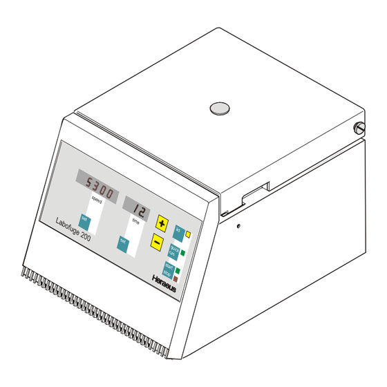
- Seite 3 ® Einfach zu bedienen Die Heraeus ® Labofuge 200 besticht durch funktionelles und elegantes ergonomisches Design. Der günstige Anschaffungspreis ist ein zusätzliches Plus. Sie lässt sich ideal in Arztpraxen und kleineren Laboratorien sowie als Stand-by-Gerät in Großlabors einsetzen. Vorteile einfachste Bedienbarkeit preisgünstiges Komplettsystem...
-
Seite 4: Technische Daten
Internet http://www.kendro.de Kendro Laboratory Products – Ein internationales Unternehmen, hervorgegangen aus der Fusion von Heraeus Instruments und Sorvall. Für Kontakte mit weiteren internationalen Niederlassungen setzen Sie sich bitte mit der internationalen Vertriebsorganisation von Hanau, Hongkong oder Newtown in Verbindung. Abweichungen von den in dieser Information enthaltenen Abbildungen und technischen Daten bleiben vorbehalten. - Seite 5 COMPACT CENTRIFUGE Easy to Use The Heraeus ® Labofuge 200 is functional and sophisticated with an ergonomic design. It is ideal for use in medical practices, clinical and small laboratories and as a stand-by unit in large laboratories. Benefits Easy to Use...
-
Seite 6: Technical Data
…and set the required time Model Order No. Labofuge 200 230 V; 50 / 60 Hz 75003630 110-120 V; 50 / 60 Hz 75003631 Accessories for Labofuge 200 230 V version 110-120 V version Angle rotor 75003760 75003760 Max. speed (rpm) 5300 5000 Max. -
Seite 7: Wartungsplan (Jährliche Durchführung Empfohlen)
Teile): Rotor- und/oder Zubehör- Teile longer, if there are visible traces of mechanical damage dürfen nicht länger benutzt werden, falls dort sichtbare Spuren von Rissen erkennbar sind Ausgabe / Edition: 03 2 - 1 Labofuge 200 18.04.02 AH... -
Seite 8: Routinemäßige Wartung Nach Zerlegung Der Zentrifuge
2.1.2.4 Protection Earth Core and Grounding Connections • Check the protection earth core for continuity and all grounding plug connectors • Isolationswiderstand und Körperstrom messen • Check isolation resistance and accessible current (see 2.5) Ausgabe / Edition: 03 2 - 2 Labofuge 200 18.04.02 AH... - Seite 9 Elektrisch oder Motorwicklung Trenn- Electrical Teile austauschen or motor winding -see test points on boards result ergebnis Ansteuerung defekt Hauptplatte austauschen Defective driving Replace main board Ausgabe / Edition: 03 2 - 3 Labofuge 200 18.04.02 AH...
- Seite 10 Short interruption of Wait for rotor standstill (appr. appears in Netzunterbrechung sek.) abwarten, neu Starten im Dreh- without mains supply 75 seconds) and re-start speed Stillstand zahlfeld braking force display Ausgabe / Edition: 03 2 - 4 Labofuge 200 18.04.02 AH...
- Seite 11 Rotor hat 10000 the display Rotor has reached Replace rotor, NV-Ram and zähler Gummipuffer ersetzen counter punkte Arbeitszyklen erreicht 10000 cycles motor supports (Service Kit) abgelaufen (Service Kit) expired leuchten illuminated Ausgabe / Edition: 03 2 - 5 Labofuge 200 18.04.02 AH...
-
Seite 12: Meßpunkte
Gerät ausschalten, switch OFF unit, Lid solenoid 105Ω Wicklungstemperatur 20°C 105Ω resistance at 20°C (68°F) at 230V units Klemme XD terminal XD resistance at 20°C (68°F) at 120V units 29Ω Ausgabe / Edition: 03 2 - 6 Labofuge 200 18.04.02 AH... -
Seite 13: Reinigung
Verschmutzte Luftschlitze in der Frontblende oder in der Bodenplatte mit einer Remove dirt from vent holes of front panel or bottom plate using a brush and Bürste reinigen und losen Schmutz absaugen vacuum cleaner Ausgabe / Edition: 03 2 - 7 Labofuge 200 18.04.02 AH... -
Seite 14: Endprüfung
- Tolerance 5% or better - Crest Factor 5 or better L (N) Körperstrom: accessible current: I [mA] = U [mV] / 500: N (L) ≡ = 1750mV = 3,5mA Ausgabe / Edition: 03 2 - 8 Labofuge 200 18.04.02 AH... -
Seite 15: Funktionen Der Hauptplatte
Allgemeine Beschreibung der Baugruppen Block Functions Die Labofuge 200 ist eine mikroprozessorgesteuerte Laborzentrifuge mit Induk- The Labofuge 200 is a microprocessor controlled laboratory tabletop centrifuge with tionsmotor und integrierter Luftkühlung. induction drive motor and integrated air cooling system. Das Gerät enthält die folgenden Baugruppen (siehe Blockschaltbild 4-1): The unit incorporates following boards and components (see block diagram 4-1): ·... -
Seite 16: Tasten- Und Anzeigenplatte
LED’s and the operating keys are managed by the CPU in multiplexing process. For Leuchtdioden Bedientasten werden Mikrocontroller the setting procedures serves MEGACONTROL "simple" (see Instruction Manual) Multiplexverfahren gesteuert. Als Bedieneroberfläche dient MEGACONTROL "einfach" (siehe Betriebsanleitung) Ausgabe / Edition: 02 3 - 2 Labofuge 200 16.01.02 AH... - Seite 17 Legende / legend 120°C Entriegelungsspule Phasen- Deckelschalter Lid Switch Unlocking Solenoid Kondensator Lötverbindung / solder connection Phase shift Motor Steckverbindung / plug connection capacitor Ausgabe / Edition: 02 Blockschaltbild / Block Diagram 15.01.02 AH 4 - 1 Labofuge 200...
- Seite 18 6,3AT bei 230V 6,25 bei 120V 6,3AT at 230V 6,3AT at 120V XA/1 XC/1 XC/2 XA/2 Motor Chassis Bremswiderstand Deckelspulen Deckelschalter Brake Resistor Lid solenoid Lid Switch Ausgabe / Edition: 02 Stromlaufplan / Schematic Diagram 15.01.02 AH 4 - 2 Labofuge 200...
- Seite 19 C = 6µF bei 230V C = 12µF bei 120V C = 6µF at 230V C = 12µF bei 120V Motor und Laufkondensator Motor and run capacitor Ausgabe / Edition: 02 Stromlaufplan / Schematic Diagram 15.01.02 AH 4 - 3 Labofuge 200...
- Seite 20 Bodenplatte base plate of armored housing 2x Fächerscheibe 2x fan washer 4.3 2x Mutter 2x nut M4 MOTOR Netzkabel mains cable Ausgabe / Edition: 02 Klemmplan / Wiring Diagram 15.01.02 AH 4 - 4 Labofuge 200...
- Seite 21 EXPLOSIONSZEICHNUNGEN BREAK DOWN DRAWINGS Ausgabe / Edition: 02 Bestückungsplan Hauptplatte 28, 230V / Component Plan Main Board 28, 230V 15.01.02 AH 4 - 5 Labofuge 200...
- Seite 22 BREAK DOWN DRAWINGS Leistungsteil Bedien/Anzeigenteil Power part Key and Indication part Verbindungskabel Connection cable 14 Pol Ausgabe / Edition: 02 Schaltbild Hauptplatte 28 230V, Uebersicht / Wiring Diagram Main Board 28 230V, Overview 15.01.02 AH 4 - 6 Labofuge 200...
- Seite 23 SI 6.3AT Mains 470n 470k B80C1500 SI 6.3AT 7805 T230V/9V VR3109 T40/E BLOCK 1000u 100n 100n Ausgabe / Edition: 02 Schaltbild Hauptplatte 28 230V; Leistungsteil / Wiring Diagram Main Board 28 230V; Power part 15.01.02 AH 4 - 7 Labofuge 200...
- Seite 24 DIP14 100n Bauteile nicht bestueckt Components not placed 100n 100n 100n 100n Ausgabe / Edition: 02 Schaltbild Hauptplatte 28 230V; Bedien- Anzeigenteil / Wiring Diagram Main Board 28 230V; Key and Indication part 15.01.02 AH 4 - 8 Labofuge 200...
- Seite 25 EXPLOSIONSZEICHNUNGEN BREAK DOWN DRAWINGS Ausgabe / Edition: 02 Bestückungsplan Hauptplatte 178, 120V / Component Plan Main Board 178,120V 15.01.02 AH 4 - 9 Labofuge 200...
- Seite 26 BREAK DOWN DRAWINGS Leistungsteil Bedien/Anzeigenteil Power part Key and Indication part Verbindungskabel Connection cable 14 Pol Ausgabe / Edition: 02 Schaltbild Hauptplatte 178 120V, Uebersicht / Wiring Diagram Main Board 178 120V, Overview 15.01.02 AH 4 - 10 Labofuge 200...
- Seite 27 Netz SI 6.25AT Mains 470n 470k B80C1500 SI 6.25AT 7805 T120V/10V BVEI38-12/0044/003 1000u 100n 100n Ausgabe / Edition: 02 Schaltbild Hauptplatte 178 120V; Leistungsteil / Wiring Diagram Main Board 178 120V; Power part 15.01.02 AH 4 - 11 Labofuge 200...
- Seite 28 DIP14 100n Bauteile nicht bestueckt Components not placed 100n 100n 100n 100n Ausgabe / Edition: 02 Schaltbild Hauptplatte 178 120V; Bedien- Anzeigenteil / Wiring Diagram Main Board 178 120V; Key and Indication part 15.01.02 AH 4 - 12 Labofuge 200...
-
Seite 29: Gehäuseteile Demontieren
Press the casing upwards and remove it from the bottom plate passing the front · Gerät sinngemäß in umgekehrter Reihenfolge montieren panel in vertical position · Reassemble the instrument analogously in reverse order Ausgabe / Edition: 02 5 - 1 Labofuge 200 16.01.02 AH... -
Seite 30: Austausch Elektrischer Komponenten
(see imprinted arrow on rim of rotor Gerät sinngemäß in umgekehrter Reihenfolge wieder zusammenbauen und chamber)! Testlauf mit Drehrichtungskontrolle (siehe Pfeil neben Kammerwand) durchführen Ausgabe / Edition: 02 5 - 2 Labofuge 200 16.01.02 AH... -
Seite 31: Ausbau Von Antriebskomponenten
· Reassemble the device in reverse order · Gerät sinngemäß in umgekehrter Reihenfolge wieder zusammenbauen · At last perform a test run · Anschließend einen Testlauf durchführen Ausgabe / Edition: 02 5 - 3 Labofuge 200 16.01.02 AH... - Seite 32 Check the lid's correct closing and self-acting opening functions after the · Nach dem Einbau überprüfen, ob der Deckel korrekt schließt und selbsttätig correct installation and replace the rubber profile (206) öffnet, eventuell die Gummidichtung (206) austauschen Ausgabe / Edition: 02 5 - 4 Labofuge 200 16.01.02 AH...
- Seite 33 AUSBAUANLEITUNG DIASSEMBLY OF INSTUMENT PARTS Service Kit für Labofuge 200 / Medifuge 200 Service Kit for Labofuge 200 / Medifuge 200 In diesem Service Kit sind alle Teile enthalten, die nach Ablauf von 10000 This service kit includes all parts which have to replaced after termination of 10000 Arbeitszyklen auszutauschen sind.
- Seite 34 EXPLOSIONSZEICHNUGEN BREAK DOWN DRAWINGS Ausgabe / Edition: 02 Gehäuseteile / Cabinet 15.01.02 AH 6 - 1 Labofuge 200...
- Seite 35 EXPLOSIONSZEICHNUGEN BREAK DOWN DRAWINGS Ausgabe / Edition: 02 Panzerung, Antrieb / Armouring, Drive 15.01.02 AH 6 - 2 Labofuge 200...
-
Seite 36: Ersatzteilliste
Ersatzteil-Liste Kendro Laboratory Products Werk Osterode 75003630 LABOFUGE 200 230V 50/60HZ von Fabriknr.: bis Fabriknr.: Index Artikelnr. Text 00101 20460133 EJOT PT KB 030X014 SCHR LINS KR 00102 20022598 FRONTBLENDE 00103 20022604 TASTERFOLIE LABO 200 HS 00105 20290521 MOOSGUMMI RUND 2,0 MM EPDM S... - Seite 37 Ersatzteil-Liste Kendro Laboratory Products Werk Osterode 75003630 LABOFUGE 200 230V 50/60HZ von Fabriknr.: bis Fabriknr.: Index Artikelnr. Text 00316 20022874 GUMMIPUFFER RD 14X30,TAILLIER 00322 20480130 D0125 043 SCHEIBE VA 00323 20190169 NETZKABEL 3X1 MM EU 00324 20220569 BEFESTG.-SCHELLE F 9.5MM KABE...
-
Seite 38: Spare Part List
20022604 KEY FOIL 00105 20290521 SEAL (FOAM RUBBER) 00110 20150103 MAINBOARD 00111 20460137 SCREW 3X8 00112 70901052 NV-RAM LABOFUGE 200 NEW 00113 20230145 FUSE 00121 20250031 WASHER 00122 20460132 SREW 3,5 X 8 00204 20460088 SCREW M5 X 8 00205... - Seite 39 ANTIVIBRATION MOUNT 00322 20480130 WASHER 4,3 00323 20190169 MAINS CABLE 00324 20220569 CLIP 00325 20480244 LOCK WASHER 00326 20290189 CABLE SHEATH 00327 20540048 CAPACITOR 00330 70901001 SERVICE KIT LABOFUGE 200 00331 20053358 ROTOR NUT Seite 2 Donnerstag, 17. Januar 2002...
- Seite 40 Spare-Part-List Kendro Laboratory Products Plant Osterode LABOFUGE 200, 120V+10%-15% 50/60HZ 75003631 to Serial-No. from Serial-No. Index Partno. Text 00101 20460133 SCREW 3X14 00102 20022598 FRONT PANEL 00103 20022604 KEY FOIL 00105 20290521 SEAL (FOAM RUBBER) 00110 20150178 MAINBOARD 120 V...
- Seite 41 Spare-Part-List Kendro Laboratory Products Plant Osterode LABOFUGE 200, 120V+10%-15% 50/60HZ 75003631 to Serial-No. from Serial-No. Index Partno. Text 00308 20220416 CABLE-CLIP 00310 20210275 MOTOR 00311 20020738 MOTOR COVER 00313 20420070 NUT M 6 00314 20480251 SECURING WASHER 00315 10104080 WASHER (SAND)
-
Seite 42: Funktionsprüfung
Kendro Service Information Heraeus Zentrifugen Labofuge 200 Medifuge 200 Vorbeugende Wartung - Checkliste Type Rotor Inspektion Parameterprüfung Allgemeine Sichtprüfung o Beschleunigungszeit ________sec Befestigungsmutter o Maximaldrehzahl ________min-1 Verfallsdatum Rotor o Bremszeit ________sec ......o Zeit (10 min Vorwahl) ________tatsächlich min:sec Stand des Zykluszählers ...... - Seite 43 Kendro Service Information Kommentar: Unterschrift ____________________ Datum ____________________ Revised – 16/01/02 2 of 2...
- Seite 44 Kendro service Information Heraeus Centrifuges Labofuge 200 Medifuge 200 PREVENTIVE MAINTENANCE CHECKLIST Type Rotor Inspection Performance Checks Visual inspection o Acceleration time ________seconds Rotor locking screw o Instrument top speed ________rpm Expiry date o Deceleration time ________seconds ......o Time (10 minute set)
- Seite 45 Kendro service Information Comments: S.R. Signature ____________________ Date ____________________ Revised – 16/01/02 2 of 2...