Seite 1
Leica DM LSP Instructions · Bedienungsanleitung Mode d’emploi M I C R O S Y S T E M S...
Seite 2
Leica DM LS en français, allemand A special brief instruction manual for the et anglais qui est également fourni avec chaque DM LSP is also available in several languages. microscope polarisant Leica DM LSP. Le mode Information about the range of objectives is d’emploi du Leica DM LS contient des données...
Seite 3
Leica DM LSP Instructions M I C R O S Y S T E M S...
Contents Pol components ............ 5 Adjustment.............. 7 Operation of objectives (Pol) ......8 Operation of transmitted light polarization ..9 Evaluation of conoscopy ........14 Possible errors ............15 Incident light techniques ........15 EU conformity declaration ........16 Text Symbols and their meaning: Caution! Operation errors can dam- age the microscope and/or its acces- sories.
5 – 51. However, all points of Ordinary tubes can also be used for polarization the DM LS manual apply to the DM LSP as well microscopy, although the orientation of the cross as long as it is equipped with the relevant com- line in the eyepiece is not then guaranteed.
Seite 6
Quartz plate. This has a depolarizing effect. Analyser mount TL L 1/25 (option) If the tube is mounted directly to the micro- (not illustrated) scope, i. e. without the Pol module and there- In case of alternative outfits without Pol module, fore without the quartz plate, anomalous inter- the modular analyser mount TL L 1/25 (11 505 121) ference colours (pseudodichroism) may occur...
Adjustment Objective centration Method II (Fig. 42) Objectives are centered by adjusting (43.14) them with two Allen keys (1.3; 43.15) until the Move the prominent point on the specimen (42a) optical axis of the objective (and therefore the to the centre of the crossline M. Rotate the stage centre of the image) matches the axis of rotation until the point on the specimen is furthest away of the specimen stage (41 and 42).
Operation of transmitted light polarization A particularly exact way of crossing the polar- izers is to use the built-in Bertrand lens (43.3) or the auxiliary telescope (25.1) as follows: Use an objective with a fairly high magnification, e. g. 40x, 50x, 63x. Open the aperture diaphragm (43.7) (PH position).
Seite 10
λ and λ/4 compensator Crossed polarizers The DIN and ISO standard vibration directions Depending on the microscope model, the quar- are indicated on the microscope (sticker). ter- and whole-wave compensators are either slotted in the compensator slot (43.20) or above If the specimen contains many non-birefringent the polarizer (43.10;...
Seite 11
Quartz wedge Compensators for quantitative measurements The quartz wedge (46.6) is inserted into the com- Only in conjunction with polarized light micro- pensator slot (43.20). It allows phase shifts from scopes in transmitted light. Adjustable compen- 0 to about 4 λ (orders). sators are used for exact measurements of phase differences.
Seite 12
To perform the measurement, the compensator Tilting compensator K, is introduced into the tube slot and adjusted until measuring up to 30 orders (like 46.7) the object to be measured is in its maximum For the measurement of phase differences in extinction position.
Seite 13
Conoscopy of crystals Setting the microscope for conoscopy Birefringent crystals cause interference patterns The most suitable object areas for conoscopy (Fig. 47) in the exit pupil of the objective (i. e. are those that show the lowest possible phase inside the objective). These are also called differences (chart in Fig.
Evaluation of conoscopy Determination of optical character Biaxial crystals (Fig. 47) Cutting directions where the bisectrix of the two Uniaxial crystals (Fig. 47) optical axes is parallel to the viewing direction (section vertical to the acute bisectrix) are par- Uniaxial crystals observed in the conoscopic ticularly suitable for determining the optical (divergent) beam show a dark cross, whose cen- character.
Possible errors Biaxially positive crystals: The interference fringes move from the convex to the concave side of the isogyres when a com- Polarizers damaged (discoloured) by powerful pensator is operated. light sources or dirty. Objectives or condenser strained through Biaxially negative crystals: mechanical damage.
European Union. This declaration will cease to be valid if the instrument is modified without our consent. Product name: DM LSP Instrument type: Microscope Instrument no.:...
Seite 17
Leica DM LSP Bedienungsanleitung M I C R O S Y S T E M S...
Seite 18
Inhalt Pol-Komponenten ..........5 Justierung .............. 7 Bedienung Objektive (Pol) ........8 Bedienung Durchlicht-Polarisation ....9 Auswertung Konoskopie........14 Fehlermöglichkeiten ..........15 Auflichtverfahren ..........15 EU-Konformitätserklärung ........16 Textsymbole und ihre Bedeutung: Achtung! Bei einer Fehlbedienung können Mikroskop bzw. Zubehörteile beschädigt werden.
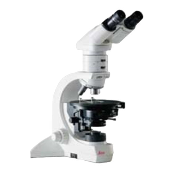
Komponenten HC L3TP 4/5/7 Trinokularer Pol-Tubus mit 3 Schaltstellungen (Intensitätsverhältnis bin: Das Mikroskopmodell DM LSP (Abb. 43) unter- vertikaler Ausgang 100 : 0 %/50 : 50 %/0 :100 %). scheidet sich in folgenden Punkten vom auf S. 5 – 51 beschriebenen Modell DM LS. Alle Für die Polarisationsmikroskopie sind auch nor-...
Seite 20
Bertrandlinse, aus- und einschaltbar (43.3) und Polarisator zentrierbar (43.3a), für Konoskopie Seite 9, Wahlweise kann der Polarisator (43.10), um 360° mit gekoppelter Lochblende zur konosko- drehbar und ausschwenkbar, mit darüber befind- pischen Ausblendung kleiner Objektbereiche. lichem Aufnahmeschlitz für λ- bzw. λ/4-Platte Quarzplatte.
Justierung Objektivzentrierung Methode II (Abb. 42) Bei der Objektivzentrierung werden die Objektive Markante Objektstelle (42a) in die Mitte des mit Hilfe zweier Sechskantschlüssel (1.3; 43.15) Strichkreuzes M verschieben. Objekttisch dre- so lange verschoben (43.14), bis die optische hen, bis die Objektstelle am weitesten von der Achse des Objektivs (und damit die Bildmitte) mit Strichkreuzmitte M entfernt ist (Position A, der Drehachse des Objekttisches übereinstimmt...
Bedienung Durchlicht-Polarisation Besonders exakt kann die Einstellung bei Ver- wendung der eingebauten Bertrandlinse (43.3) oder des Einstellfernrohres (25.1) wie folgt vor- genommen werden: Objektiv stärkerer Vergrößerung benutzen, z. B. 40x, 50x, 63x. Aperturblende (43.7) öffnen (Pos. PH). Bei Einstellfernrohr: so fokussieren, daß der etwas aufgehellte Kreis im Zentrum des Sehfel- des scharf begrenzt ist.
Seite 24
λ/4- und λ-Platte Gekreuzte Polarisatoren λ/4- und λ-Platte werden je nach Ausführung in Nach DIN und ISO verlaufen die Schwingungs- richtungen entsprechend der Beschriftung auf den Kompensatorschlitz (43.20) oder über dem dem Stativ (Aufkleber). Polarisator (43.10; 28.2) oder in Lichtringschlitz (CLP/PH) eingesteckt oder in die Kondensor- Enthält das Präparat viele nichtdoppelbrechende scheibe (UCLP) (9.6) eingebaut.
Seite 25
Quarzkeil Kompensatoren für quantitative Messungen Der Quarzkeil (46.6) wird in den Kompensator- Nur in Verbindung mit Polarisationsmikroskopen schlitz (43.20) eingesteckt. Er erlaubt Phasen- im Durchlicht. Verstellbare Kompensatoren dienen verschiebungen von 0 bis ca. 4 λ (Ordnungen). zur exakten Messung von Gangunterschieden. Bei bekannter Objektdicke d und dem gemesse- Zirkularpolarisation nen Gangunterschied Gamma (Γ) kann die...
Seite 26
Bei der Messung wird der Kompensator in den Kippkompensator K Kompensatorschlitz eingeführt und so lange ver- mit Meßbereich bis 30 Ordnungen (wie 46.7) stellt, bis sich die zu messende Objektstelle in Zur Messung von Gangunterschieden in weißem maximaler Dunkelstellung befindet. Das Objekt oder monochromatischem Licht bis zum angege- muß...
Seite 27
Konoskopie von Kristallstrukturen Einstellen Konoskopie Doppelbrechende Kristalle zeigen in der Aus- Für die Konoskopie sind am geeignetsten die trittspupille des Objektivs (d. h. innerhalb des Objektstellen, die möglichst niedrige Gangunter- Objektivs) Interferenzbilder (Abb. 47), die auch schiede aufweisen (Tabelle Abb. 45). Voraus- Achsenbilder oder Konoskopbilder genannt wer- setzung für einwandfreie konoskopische Be- den.
Auswertung Konoskopie Bestimmung des optischen Charakters Zweiachsige Kristalle (Abb. 47) Für die Bestimmung des optischen Charakters Einachsige Kristalle (Abb. 47) sind besonders die Schnittlagen geeignet, bei welchen die Winkelhalbierende der beiden opti- Einachsige Kristalle zeigen bei der Beobachtung schen Achsen parallel zur Blickrichtung verläuft im konoskopischen (divergenten) Strahlengang (Schnitt senkrecht zur spitzen Bisektrix).
Fehlermöglichkeiten Zweiachsige positive Kristalle: Die Verschiebung der Interferenzstreifen verläuft beim Zuschalten eines Kompensators von der Polarisatoren durch starke Lichtquellen konvexen zur konkaven Seite der Isogyren. geschädigt (verfärbt) oder stark verschmutzt. Objektive oder Kondensor durch mechanische Zweiachsige negative Kristalle: Beschädigung verspannt. Die Bewegungsrichtung der Interferenzstreifen Strahlenteiler oder Filter zwischen den Polari- verläuft von der konkaven zur konvexen Seite.
Hiermit erklären wir, daß nachfolgend bezeichnetes Gerät aufgrund seiner Konzipierung und Bauart sowie in der von uns in Verkehr gebrachten Ausführung den einschlägigen grundlegenden Sicherheits- und Gesundheitsanforderungen der EU-Richtlinien entspricht. Bei einer nicht mit uns abgestimmten Änderung des Gerätes verliert diese Erklärung ihre Gültigkeit. Bezeichnung: DM LSP Gerätetyp: Mikroskop Gerätenummer: 551030...
Seite 31
Leica DM LSP Mode d’emploi M I C R O S Y S T E M S...
Seite 32
Sommaire Les composants Pol ..........5 Réglages..............7 Utilisation des objectivs (Pol) ......8 Utilisation de la polarisation en lumière transmise ..........9 Interprétation de la conoscopie ......14 Sources d’erreurs ..........15 Procédé de lumière réfléchie ......15 Déclaration de conformité UE ......16 Les symboles et leur signification : Attention ! Une erreur de l’opérateur peut endommager le microscope,...
Pour utiliser d’autres réticules du DM LS est toutefois valable pour la version (pour la microphotographie, par exemple) il faut DM LSP dans la mesure ou l’on dispose des com- commander un oculaire supplémentaire (3°) car posants nécessaires. Seuls les composants sui- il est très gênant d’avoir deux réticules différents...
Seite 34
un coin de quartz. Il a une fonction dépolari- Logement pour analyseurs TL L 1/25 (option) sante. Si on installe le tube directement sur le (non illustré) microscope, sans module Pol, c’est à dire Dans le cas d’équipements alternatifs sans sans coin de quartz, on risque d’obtenir des module de polarisation, le logement modulaire couleurs interférentielles anormales (pseudo-...
Réglages Le centrage des objectifs 2° méthode (Fig. 42) Centrer les objectifs (43.14) à l’aide des deux Déplacer un point remarquable de la préparation clefs à six pans (1.3 ; 4.3) jusqu’à ce que l’axe (42a) jusqu’au milieu M du réticule en croix. Puis, optique des objectifs (donc le milieu de l’image) faire tourner la platine jusqu’à...
BF (Fond clair). Avec condenseur CLP/PH* (43.8) retirer l’anneau de lumière. Mettre l’analyseur en service (43.4). Fig. 43 Les commandes du microscope polarisant Leica DM LSP 1 Oculaires à lentille réglable* et à œillère amovible, 2 Réglage de l’écart interpupillaire, 3 Lentille de Bertrand, en service/au repos, 3a Système de centrage de la lentille de...
Utilisation de la polarisation en lumière transmise On peut faire le réglage de manière particulière- avec des microscopes non polarisants car ils ne ment précise en utilisant la lentille de Bertrand possèdent pas de lamelle de quartz dépolarisan- incorporée dans le microscope (43.3) ou la lunet- te.
Seite 38
Lame λ/4 et λ Polariseurs croisés Selon DIN et ISO, les directions vibratoires sont On introduit la lame d’onde ou de quart d’onde telles qu’inscrites sur le statif (autocollant). dans la fente du compensateur (43.20), au-des- sus du polariseur (43.10 ; 28.2) ou dans la fente Si la préparation contient beaucoup de parti- du condenseur CLP/PH ou dans le barillet cules non biréfringentes ou opaques, il faut faire...
Seite 39
Lamelle de quartz Les compensateurs pour mesures quantitatives On introduit la lamelle de quartz (46.6) dans la A n’utiliser que pour les microscopes polari- fente du compensateur. Elle permet un déplace- sants en lumière transmise. Les compensateurs ment de phase de 0 jusqu´à approximativement réglables servent à...
Seite 40
Pour effectuer les mesures, introduire le com- Le compensateur K pensateur dans la fente du tube et le régler avec domaine de mesures allant jusqu´à jusqu´à ce que le champ-objet à mesurer soit le 30 longueurs d’onde (comme 46.7) plus sombre possible. Pour ce faire, il faut placer Mesure de différences de phase en lumière l’objet dans une certaine position diagonale.
Seite 41
Conoscopie de structures cristalliques Le réglage de la conoscopie Les cristaux biréfringents font apparaître des Plus les plan-objets ont une différence de phase images interférentielles (Fig. 47), également basse, mieux ils sont adaptés à la conoscopie appelées figures d’axes ou images conosco- (voir tableau 45).
Interprétation de la conoscopie Détermination du caractère optique Cristaux biaxiaux (Fig. 47) Pour la définition du caractère optique, il est Cristaux à axe unique (Fig. 47) recommandé d’utiliser des sections pour les- Avec les cristaux à axe unique, lors d’observa- quelles la bissectrice des deux axes optiques est tions dans le trajet optique conoscopique (diver- parallèle à...
Sources d’erreurs Cristaux biaxiaux positifs : Quand on met le compensateur en service, les franges d’interférence se déplacent du côté Polariseurs salis ou endommagés (délavés) convexe des hyperboles au côté concave. suite à l’utilisation de sources de lumière trop puissantes. Cristaux biaxiaux négatifs : Tensions dans les objectifs ou le condenseur Déplacement des franges d’interférence du côté...
Cette déclaration perd toute validité en cas de modifications apportées sur l’appareil sans notre autorisation. Désignation : DM LSP Produit : Microscope optique d’identification : 551 030...
Seite 46
Tel. +49 (0) 64 41-29 0 Leica Microsystems Wetzlar GmbH Ernst-Leitz-Straße Fax +49 (0) 64 41-29 25 99 www.leica-microsystems.com D-35578 Wetzlar (Germany) M I C R O S Y S T E M S...