Herunterladen Inhalt Inhalt Diese Seite drucken
Inhaltsverzeichnis

Werbung

Verfügbare Sprachen

Verfügbare Sprachen

Montage- und Betriebsanleitung
DE
Kleinraumventilatoren
Mounting and Operating instructions
UK
Small room fans
Instructions de montage et Mode d'emploi
FR
Aérateurs pour petites pièces
w w w . m a i c o - v e n t i l a t o r e n . c o m
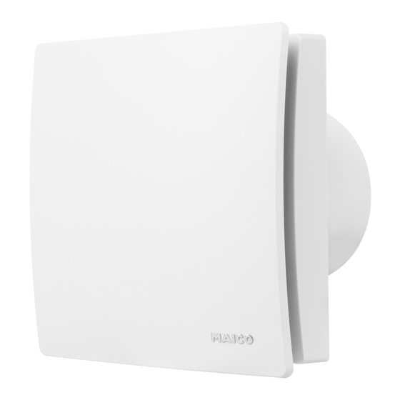
ECA 100 ipro
ECA 100 ipro VZC
ECA 100 ipro F
ECA 100 ipro H
ECA 100 ipro B
ECA 100 ipro K
ECA 100 ipro KVZC
ECA 100 ipro KF
ECA 100 ipro KH
ECA 100 ipro KB

Werbung

Inhaltsverzeichnis
loading

Inhaltszusammenfassung für Maico ECA 100 ipro

  • Seite 1 Mounting and Operating instructions Small room fans Instructions de montage et Mode d’emploi Aérateurs pour petites pièces ECA 100 ipro ECA 100 ipro VZC ECA 100 ipro F ECA 100 ipro H ECA 100 ipro B ECA 100 ipro K...
  • Seite 2: Lieferumfang

    Page 34 Éléments fournis Lieferumfang Scope of delivery ● Aérateur pour petites ● Kleinraumventilator ● Small room fan pièces ECA 100 ipro ECA 100 ipro ECA 100 ipro ● Cache de protection ● Elektronikabdeckung ● Electronics cover de l’électronique ● Sensor (nur bei ●...
  • Seite 4: Inhaltsverzeichnis

    Betrieb .......... 6 ● Luftführung über Schacht oder Rohr. 7. Technische Daten ........6 ● elektrischem Unterputz-Anschluss. 8. Montagevorbereitungen ......6 8.1 Wand ..........6 Impressum: © Maico Elektroapparate-Fabrik GmbH. Deutsche Originalanleitung. Druckfehler, Irrtümer 8.2 Decke ..........6 und technische Änderungen vorbehalten...
  • Seite 5: Sicherheitshinweise Und Warnungen

    2. Bestimmungsgemäße Verwendung │ DE Einbau in Fenster mit Fenstereinbausatz Fett- und Öldämpfe von Dunstab- FE 100/1, Anschluss an Flachkanäle mit zugshauben können den Ventilator Distanzrahmen ECA-DR zulässig. und die Luftleitungen verschmutzen und die Leistungsfähigkeit reduzieren. Dieses Gerät ist ausschließlich für den Ventilator auf keinen Fall zur Förderung häuslichen Gebrauch und ähnliche Zwecke fetthaltiger Luft verwenden, z.
  • Seite 6: Bedienung

    DE │ 3. Sicherheitshinweise und Warnungen Ein nicht ordnungsgemäß einge- Gefahr bei Nichtbeachtung der bauter Ventilator kann einen nicht geltenden Vorschriften für Elektro- bestimmungsgemäßen/unzulässigen installationen. Betrieb verursachen. Der Betrieb ist nur bei  Vor Elektroinstallationen alle Versorgungs- korrekter Einbaulage (siehe „TOP“ auf stromkreise abschalten, Netzsicherung Gerät), mit montierter Designabdeckung und ausschalten und gegen Wiedereinschalten...
  • Seite 7: Produktinformationen

    ● ECA 100 ipro mit feststehendem Feuchtewert wird als erster Referenzwert Innengitter. gespeichert. Eine manuelle Vorgabe des ● ECA 100 ipro K mit elektrisch betätigtem Referenzwertes ist nicht nötig. Innenverschluss. Sinkt die relative Feuchte während des Be- ● Zwei Leistungsstufen serienmäßig.
  • Seite 8: Umgebungsbedingungen Und Grenzen Für Den Betrieb

    DE │ 5. Produktinformationen nicht unterschritten, schaltet das Gerät in den 8.1 Wand eingestellten Nachlaufbetrieb und danach Aus. Vorgeschriebene Mindestabstände H und KH Geräte können optional per Licht- zur Wand und Decke gemäß Abbil- schalter bedient werden. Bei „Licht an“ startet dung einhalten.
  • Seite 9: Rohr

    [4] korrekt aufsetzen).  Leitungstülle [3] fachgerecht anbringen, 2. Beigefügtes Schaumstoffband am Stutzen ggf. bauseitig abdichten. mittig anbringen. An ECA 100 ipro H und KH unbedingt das Schaumstoffband anbringen, damit die Geräte keine Fehlluft von außen anziehen. 9. Montage Bei Einbau mit Fenstereinbausatz FE 5.
  • Seite 10: Elektrischer Anschluss

    Leistungsstufe 2 während der anschließen, siehe auch Schaltbilder Nachlaufzeit. in Kapitel 15. ● J4 gebrückt, J5 gebrückt ECA 100 ipro-Geräte in Standard- ausführung sind mit Doppelschal- tern zweistufig bedienbar. Ohne Doppelschalter lässt sich der Ventila- tor entweder in Leistungsstufe 1 oder in Leistungsstufe 2 betreiben, siehe Schaltungsvarianten in Kapitel 15.
  • Seite 11 9. Montage, Elektrischer Anschluss │ DE Nachtprogramm 2. Elektronikabdeckung anbringen. ● Leistungsstufe 2 während der Raum- ACHTUNG nutzung, Leistungsstufe 1 während der Nachlaufzeit. Kurzschlussgefahr und Gerätebeschädi- ● J4 offen, J5 offen gung. Eindringende Feuchtigkeit bei falsch eingesetzter Elektronikabdeckung.  Elektronikabdeckung fest an das Gehäuse drücken, so dass diese ringsum dichtend und plan anliegt.
  • Seite 12: Inbetriebnahme

    Betriebs sind die LED´s aus. Für Auslieferungszustand siehe ACHTUNG Tabelle in Kapitel 5.1. Bei ECA 100 ipro K: Lamellenbruch bei falschem Reinigen. 1. Designabdeckung [7] vorsichtig abnehmen  Vorsicht beim Reinigen. Lamellen nicht ( Ausklappseite, Abbildung B). zu stark öffnen, schließen oder verbiegen.
  • Seite 13: Demontage

    12. Störungsbehebung │ DE Störung Ursache, Maßnahme Störung Ursache, Maßnahme Ventilator Keine Netzspannung. Ventilator Durch eine Glimmlampe im schaltet schaltet nicht Kontrollschalter, parallel ver- Prüfen, ob die Netzsicherung nicht ein. aus oder legte Leitungen (Induktion) ausgefallen ist. Diese ggf. Ventilator oder Transformatoren bzw.
  • Seite 14: Specialist Installer Qualification

    UK │ Table of contents 8.3 Duct ..........17 ECA 100 ipro fans 8.4 Fan..........17 9. Installation ..........17 Please read the instructions carefully 9.1 Installing housing ......17 before mounting and using for the 9.2 Electrical connection ....... 18 first time.
  • Seite 15: Safety Instructions And Warnings

    2. Intended use │ UK An operation is only permitted with: Grease and oil vapours from range ● permanent installation inside of buildings. hoods may contaminate the fan and ● installation on walls or ceilings. ventilation ducts and reduce ● air supply via shaft or pipe. efficiency.
  • Seite 16 UK │ 3. Safety instructions and warnings A fan that is not installed correctly Danger if the relevant regulations for may result in non-intended operation electrical installations are not or impermissible operation. Operation observed. is only permitted with a correct installation ...
  • Seite 17: Operation

    Once the fan is installed, it adjusts itself rooms. to the prevailing room humidity (relative ● ECA 100 ipro with fixed internal grille. humidity). This humidity value is saved as the ● ECA 100 ipro K with electrically operated first reference value. The reference value internal shutter.
  • Seite 18: Environmental Conditions And Operating Limits

    UK │ 5. Product information If the room humidity increases by 7 %, the fan 7. Technical data engages automatically at performance level 1 (78 m³/h). Rated voltage 230 V AC ● If the room humidity increases even Power frequency 50 Hz further, the unit switches to performance level 2 (92 m³/h).
  • Seite 19: Ceiling

    8.2 Ceiling centre. The foam strip must be fitted to NOTICE ECA 100 ipro H and KH such that Danger of short-circuits and damage to the units do not draw in any unit if condensation builds up in the fan unwanted air from outside.
  • Seite 20: Electrical Connection

    [13] according to connection wiring diagram [14], also see wiring diagrams in Chapter 15. ECA 100 ipro standard model units can be operated at two levels with double switches. Without a double switch, the fan can either be opera-...
  • Seite 21 9. Installation │ UK 1. Set the operating program you want with jumpers J4 and J5. Comfort program ● Performance level 1 while room is being used, performance level 2 during overrun time. Power program ● J4 bridged, J5 bridged ●...
  • Seite 22: Start-Up

    When the setting button is pressed NOTICE for the first time, the value currently set is displayed. The LEDs are off For ECA 100 ipro K: lamella may break if during operation. cleaned incorrectly.  Take care when cleaning. Do not exercise force when For condition in which unit is opening, shutting or bending the lamella.
  • Seite 23: Fault Rectification

    11. Cleaning │ UK 1. Switch off mains fuse, secure against being accidentally switched back on and position a warning sign. 2. Only clean inside parts of the fan with a dry cloth. 3. If the designer cover [7] is very dirty, remove it carefully (...
  • Seite 24: Dismantling

    11 Touche de réglage de temporisation de démarrage 12 Touche de réglage de la durée de fonctionnement par temporisation Mentions légales © Maico Elektroapparate Fabrik GmbH. Cette instruc- tion est une traduction de l'instruction allemande originale. Sous réserve de fautes d'impression, d'erreurs et de modifications techniques.
  • Seite 25: Qualification De L'installateur Spécialisé

    Sommaire │ FR On entend par électricien qualifié une Sommaire personne qui, par son apprentissage, sa formation et son expérience connaît les 1. Qualification de l'installateur spécialisé .. 23 normes et directives en vigueur, est capable 2. Utilisation conforme ....... 23 d'exécuter les branchements électriques 3.
  • Seite 26 FR │ 3. Consignes de sécurité et avertissements Ne jamais utiliser le ventilateur dans les Respectez toutes les instructions situations suivantes. de sécurité. Risque d'inflammation/d'incendie Danger pour les enfants et résultant de la présence de maté- les personnes ayant des riaux, liquides ou gaz combustibles à...
  • Seite 27 3. Consignes de sécurité et avertissements │ FR Si le ventilateur n'est pas monté panneau d'avertissement de manière bien correctement, son exploitation peut visible. N'utiliser le ventilateur qu'après son être non conforme/non autorisée. montage complet. Ne pas mettre en service L'exploitation du ventilateur n'est admissible un appareil endommagé.
  • Seite 28: Commande

    ● Aérateur pour petites pièces pour la fonction de l’humidité pour les appareils ventilation de pièces. H et KH ● ECA 100 ipro avec grille intérieure fixe. Après l'installation du ventilateur, celui-ci ● ECA 100 ipro K avec fermeture intérieure se règle sur l'humidité ambiante relative à...
  • Seite 29: Conditions Ambiantes Et Limites D'utilisation

    5. Informations produit │ FR Si l'humidité relative passe sous la valeur sont nécessaires (composants L, C ou de référence pendant le fonctionnement, la RC, diodes de protection, varistors), ces nouvelle valeur saisie est alors enregistrée valeurs risquant d'être dépassées. comme valeur de référence.
  • Seite 30: Plafond

    2. Mettre en place la bande de mousse jointe Préparations de montage comme décrit au au centre des tiges. chapitre 8.1. Sur l’ECA 100 ipro H et KH mettre obligatoirement en place la bande de mousse, de façon à ce que les ap- 8.3 Gaine pareils n’attirent aucun air d’appoint.
  • Seite 31: Branchement Électrique

    9. Montage │ FR 5. Mettre en place le manchon du câble [3] sur le boîtier. 6. Mettre en place le câble secteur dans l’espace de raccord de façon à ce que le manchon du câble entoure complètement la gaine du câble. Faire en sorte qu’il ne dépasse pas trop avant dans l’espace de raccord 9.2 Branchement électrique...
  • Seite 32: Programmes De Commande

    FR │ 9. Montage Les appareils ECA 100 ipro en ver- ● J4 ponté, J5 ponté sion standard peuvent être com- mandés par un double interrupteur. Sans double interrupteur, il est possible d’exploiter le ventilateur soit au niveau de puissance 1, soit au niveau 2 (voir les variantes de commutation au chapitre 15).
  • Seite 33: Mise En Service

    9. Montage │ FR Powerprogramme ● Niveau de puissance 2 lors du fonc- tionnement et du fonctionnement par temporisation. ● J4 ponté, J5 ouvert 4. Pour les versions F, KF, H, KH, B et KB enfoncer le capteur livré [9] en position correcte (...
  • Seite 34: Maintenance

    Intervention devant être ATTENTION uniquement réalisée par un ne se met Pour le ECA 100 ipro K : Risque de spécialiste : Retirer le cache rupture en cas de nettoyage incorrecte- [6]. Débloquer la grille intérieure en marche. ment effectué.
  • Seite 35: Démontage

    12. Élimination des défauts │ FR Dysfonc- Cause tionnement Mesure Le ventilateur Cela peut provenir de la lueur ne s'éteint du témoin d’allumage lumi- pas ou le nescent de l’interrupteur, ou ventilateur des fils électriques installés s’allume de en parallèle (induction), ou du façon transformateur, ou encore inopinée.
  • Seite 36: Schaltbilder

    DE │ UK │ FR │ 15. Schaltbilder / Wiring diagrams / Schémas de branchement 15. Schaltbilder 15. Schaltbilder / Wiring diagrams / Schémas de branchement ECA 100 ipro, ECA 100 ipro K ECA 100 ipro, ECA 100 ipro K Nenndrehzahl hohe Stufe...
  • Seite 37 15. Schaltbilder / Wiring diagrams / Schémas de branchement │ FR │ UK │ DE ECA 100 ipro, ECA 100 ipro mit/with/avec ST1/STU1 ECA 100 ipro K ECA 100 ipro K mit/with/avec ST1/STU1 2 Drehzahlstufen (hohe und niedrige Stufe) Drehzahl mit ST1/STU1 einstellbar 2 speed levels (high and low level) Rotating speed, adjustable with ST 1/STU 1 2 niveaux de vitesse (niveau élevé...
  • Seite 38 DE │ UK │ FR │ 15. Schaltbilder / Wiring diagrams / Schémas de branchement ECA 100 ipro VZC ECA 100 ipro F ECA 100 ipro KVZC ECA 100 ipro KF ECA 100 ipro H ECA 100 ipro B ECA 100 ipro KH...
  • Seite 42 Maico Elektroapparate-Fabrik GmbH • Steinbeisstr. 20 • 78056 Villingen-Schwenningen • Germany • Service +49 7720 6940 • technik@maico.de...

Inhaltsverzeichnis