Maico ECA 100 ipro VZC Montage- Und Betriebsanleitung
Kleinraumventilatoren
Vorschau ausblenden
Andere Handbücher für ECA 100 ipro VZC:
- Montage- und betriebsanleitung (52 Seiten) ,
- Montageanleitung und betriebsanleitung (34 Seiten) ,
- Montage- und betriebsanleitung (48 Seiten)
Inhaltsverzeichnis
Werbung
Verfügbare Sprachen
Verfügbare Sprachen
Montage- und Betriebsanleitung
DE
Kleinraumventilatoren
Mounting and Operating instructions
EN
Small room fans
Instructions de montage et Mode d'emploi
FR
Aérateurs pour petites pièces
w w w . m a i c o - v e n t i l a t o r e n . c o m
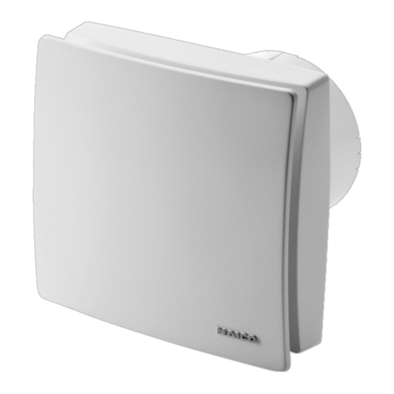
ECA 100 ipro
ECA 100 ipro VZC
ECA 100 ipro F
ECA 100 ipro H
ECA 100 ipro B
ECA 100 ipro K
ECA 100 ipro KVZC
ECA 100 ipro KF
ECA 100 ipro KH
ECA 100 ipro KB
Werbung
Kapitel
Inhaltsverzeichnis

Verwandte Anleitungen für Maico ECA 100 ipro VZC


Inhaltszusammenfassung für Maico ECA 100 ipro VZC
- Seite 1 Mounting and Operating instructions Small room fans Instructions de montage et Mode d’emploi Aérateurs pour petites pièces ECA 100 ipro ECA 100 ipro VZC ECA 100 ipro F ECA 100 ipro H ECA 100 ipro B ECA 100 ipro K...
- Seite 2 F, H et B) ● Schaumstoffband ● Foam strip ● Bande en mousse ● Montage- und ● Installation and operating ● Notice de montage et Betriebsanleitung instructions d'utilisation Zusätzliche Informationen Mit dem Smartphone direkt zum Produkt. Im Internet unter maico-ventilatoren.com.
-
Seite 4: Inhaltsverzeichnis
Sie die angegebenen Anwei- 9. Reinigung ..........10 sungen der Reihe nach durch. 10. Störungsbehebung ....... 10 11. Demontage........... 11 12. Entsorgung ........... 11 13. Schaltbilder .......... 33 Impressum: © Maico Elektroapparate-Fabrik GmbH. Deutsche Original-Betriebsanleitung. Druckfehler, Irrtümer und technische Änderungen vorbehalten... -
Seite 5: Produktinformationen
[min.] [mm²] programme steuerbar [sek.] ● ECA 100 ipro 5 x 1,5 ● ECA 100 ipro VZC 0/50/90/120 0/8/17/25 5 x 1,5 ● ECA 100 ipro F 0/50/90/120 0/8/17/25 3 x 1,5 0/50/90/120* 8/17/25** ECA 100 ipro H 3 x 1,5 ●... -
Seite 6: Bestimmungsgemäße Verwendung
Referenzwert ab, wird der 2.4 Vorhersehbare Fehlanwendungen neu ermittelte Wert als Referenzwert gespei- Maico haftet nicht für Schäden durch bestim- chert. Der kleinstmögliche Referenzwert liegt mungswidrigen Gebrauch. Gerät auf keinen bei 48 % relativer Feuchte. Steigt die Raum-... -
Seite 7: Sicherheitshinweise
5. Sicherheitshinweise │ DE Verletzungsgefahr durch 5. Sicherheitshinweise sich drehendes Flügelrad. Nicht zu nahe an das 5.1 Allgemein Gerät gehen, damit ● Montage und elektrischer An- Haare, Kleidung oder schluss nur durch Fachkräfte Schmuck nicht in das gemäß Kapitel 1 zulässig. Gerät hineingezogen ●... -
Seite 8: Montagevorbereitungen
DE │ 5. Sicherheitshinweise ● Ein zu entlüftender Raum 6.2 Decke muss mit einem unverschließ- Kurzschlussgefahr und ACHTUNG Gerätebeschädigung durch baren, freien Zuluftquerschnitt Kondenswasserbildung im von mindestens 150 cm² Ventilatorgehäuse. ausgestattet sein, z. B. mit Lüftungsleitungen fachgerecht thermisch isolieren. Kondens- Türlüftungsgitter MLK. -
Seite 9: Montage
7. Montage │ DE 7. Montage Bei Einbau mit Fenstereinbausatz FE 100/1 oder Distanzrahmen ECA-DR zugehörige Montageanleitung. 7.1 Gehäuseeinbau 1. Gehäuse [1] in Wanddurchbruch/Wand- 5. Leitungstülle [3] in Gehäuse einsetzen. hülse stecken (TOP = oben). Netzleitung so in den Anschlussraum führen, dass die Leitungstülle den Leitungsmantel komplett umschließt und nicht zu weit in den Anschluss-... -
Seite 10: Betriebsprogramme
DE │ 7. Montage ECA 100 ipro-Geräte in Standard- Nachtprogramm ausführung sind mit Doppelschal- ● Leistungsstufe 2 während der Raum- tern zweistufig bedienbar. Ohne nutzung, Leistungsstufe 1 während der Doppelschalter lässt sich der Ventila- Nachlaufzeit. tor entweder in Leistungsstufe 1 oder ●... -
Seite 11: Inbetriebnahme
7. Montage │ DE 2. Elektronikabdeckung anbringen. 7.4 Inbetriebnahme 1. Netzsicherung einschalten. Kurzschlussgefahr und Gerä- ACHTUNG tebeschädigung. Eindringende 2. Funktionstest durchführen. Feuchtigkeit bei falsch einge- setzter Elektronikabdeckung. 7.5 Einschaltverzögerung und Elektronikabdeckung fest an das Nachlaufzeit Gehäuse drücken, so dass diese Beim ersten Drücken der Einstell- ringsum dichtend und plan an- taste wird der aktuell eingestellte... -
Seite 12: Reinigung
DE │ 9. Reinigung Ventilator Keine Netzspannung. 9. Reinigung Prüfen, ob die Netzsicherung aus- schaltet gefallen ist. Diese ggf. einschalten. nicht ein. Lebensgefahr durch Strom- Laufrad blockiert. Ventilator schlag. Nur durch Fachkraft zulässig: schaltet GEFAHR Netzsicherung ausschalten. Abdeckung [6] abnehmen. nicht ein. -
Seite 13: Demontage
11. Demontage │ DE 11. Demontage 12. Entsorgung Die Demontage darf nur von einer Nicht in den Restmüll. Elektrofachkraft vorgenommen Das Gerät enthält teils wiederver- werden. wertbare Stoffe, teils Substanzen, die nicht in den Restmüll gelangen dürfen. Lebensgefahr durch Strom- schlag. -
Seite 35: Schaltbilder
13. Schaltbilder / Wiring diagrams / Schémas de branchement │ FR │ EN │ DE 13. Schaltbilder 13. Schaltbilder / Wiring diagrams / Schémas de branchement ECA 100 ipro, ECA 100 ipro K ECA 100 ipro, ECA 100 ipro K Nenndrehzahl hohe Stufe Nenndrehzahl niedrige Stufe Nominal speed, high level... - Seite 36 DE │ EN │ FR │ 13. Schaltbilder / Wiring diagrams / Schémas de branchement ECA 100 ipro, ECA 100 ipro mit/with/avec ST1/STU1 ECA 100 ipro K ECA 100 ipro K mit/with/avec ST1/STU1 2 Drehzahlstufen (hohe und niedrige Stufe) Drehzahl mit ST1/STU1 einstellbar 2 speed levels (high and low level) Rotating speed, adjustable with ST 1/STU 1 2 niveaux de vitesse (niveau élevé...
- Seite 37 13. Schaltbilder / Wiring diagrams / Schémas de branchement │ FR │ EN │ DE ECA 100 ipro VZC ECA 100 ipro F ECA 100 ipro KVZC ECA 100 ipro KF ECA 100 ipro H ECA 100 ipro B ECA 100 ipro KH...