Inhaltsverzeichnis
Werbung
Verfügbare Sprachen
Verfügbare Sprachen
Werbung
Kapitel
Inhaltsverzeichnis

Verwandte Anleitungen für Betafence Robusta SC


Inhaltszusammenfassung für Betafence Robusta SC
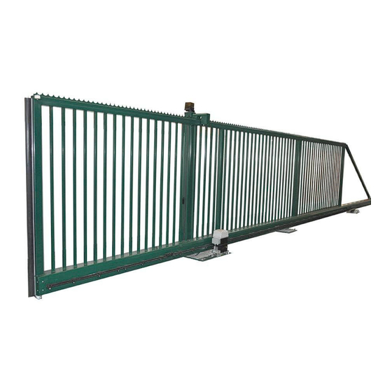
- Seite 1 INSTALLATIONSANLEITUNG INSTALLATION MANUAL FREITRAGENDE SCHIEBETORE CANTILEVER SLIDING GATE ® Robusta MOTORISIERUNG MOTORIZATION ® ® Robusta SC Freitragende Schiebetore/Cantilever sliding gate - Robusta 1/36 Ed. June 2015...
-
Seite 2: Inhaltsverzeichnis
INHALTSVERZEICHNIS SICHERHEITSHINWEISE ............. 3 1.1............3 ICHERHEITSHINWEISE FÜR NSTALLATEURE UND NWENDER 1.2....................3 ESONDERE INWEISE TEILE DES TORES ..............5 2.1........................ 5 ERPACKUNG 2.2......................... 5 EILE 2.3....................... 6 USFÜHRUNG RICHTLINIEN FÜR INSTALLATION UND ANHEBEN DES TORES .................. -
Seite 3: Sicherheitshinweise
Dieses Tor darf einzig zu dem Zweck verwendet werden, zu dem es ausschließlich bestimmt ist (das komplette System). Jeder andere Verwendungszweck ist als ungeeignet und somit als gefährlich zu betrachten. Betafence übernimmt keinerlei Verantwortung für etwaige Schäden, die aus unsachgemäßem, falschem und verantwortungslosem Gebrauch herrühren 1.2. - Seite 4 Die jährliche Wartung ist nach den Richtlinien des Herstellers durchzuführen. Wurde ein Wartungsvertrag mit Betafence vereinbart, wird die Wartung von Betafence durchgeführt. Ansonsten ist der Endbenutzer hierfür verantwortlich. Für den deutschen Markt: die verantwortliche Person für die Wartung muß auch die jährlich vorgeschriebene Messung nach DIN EN 12453 durchführen.
-
Seite 5: Teile Des Tores
2.Teile des Tores 2.1. Verpackung Das Schiebetor wird als ein Packstück geliefert. Der Motor ist nicht montiert. 2.2. Teile - 2 Pfosten - 1 Flügel - Stützrolle (freier Durchgang > 5 m) - Zubehör (Schrauben und Muttern) ist einzeln in einer Tüte verpackt - Schüssel des Schlosses (wenn Schloss vorhanden ), ist am Tor befestigt (siehe Abbildung) ®... -
Seite 6: Ausführung
2.3. Ausführung Es sind 3 Versionen lieferbar: - motorisierbar = manuelle Ausführung mit Zahnstange, ohne Schloss - Totmann = Ausführung mit Motor und Schlüsselschalter (TOTMANN) aber ohne Sicherheitseinrichtung - Automatikbetrieb = Ausführung mit Motor und Sicherheitseinrichtung • Motor mit integriertem Controller •... -
Seite 7: Richtlinien Für Installation Und Anheben Des Tores
3.Richtlinien für Installation und Anheben des Tores 1. Hebepunkte für Abladen und Positionierung während der Installation. 2. Das Tor darf nur mit geeignetem Gerät für die Bearbeitung und ausreichender Hubleistung gehoben werden. Verwenden Sie vorzugsweise einen Typ flexibler Hebeseile mit ausreichender Hebekapazität. -
Seite 8: Bodenanker
Chemische Anker M16 (mindestens 100 mm über abgeschlossenem Bodenlevel, für die benötigte Tiefe der Verankerung, richten Sie sich nach den Angaben des Lieferanten des chemischen Ankers). Betafence liefert keine chemischen Anker. 2. Markieren Sie die Positionen der Löcher mit einem Betonbohrer kleinen Durchmessers. -
Seite 9: Montage Des Tores Und Pfosten Auf Den Befestigungsankern
4.4. Montage des Tores und Pfosten auf den Befestigungsankern Positionieren Sie Führungspfosten und Schliesspfosten erst wenn das Harz vollständig ausgehärtet ist. Das Tor wird als Ganzes mit dem Führungspfosten und den hinteren Führungsrollen auf die entsprechenden Anker gestellt. Chronologische Reihenfolge der Arbeitsgänge: 1. -
Seite 10: Ausrichtung Und Nivellierung Des Tores
4.5. Ausrichtung und Nivellierung des Tores 1. Stellen Sie das Tor auf manuelle Betriebsart. Richten Sie die hinteren Führungsrollen und den Führungspfosten entsprechend der Tormittellinie aus. Stellen Sie sicher, dass der Torflügel im Führungspfosten parallel läuft. Wenn die Ausrichtung zwischen den hinteren Führungsrädern und dem Führungspfosten erfolgt ist, ziehen Sie die Muttern der Erdanker des Führungspfostens und der hinteren Führungsrollen leicht an. - Seite 11 WICHTIG! Das Stützrad im Unterholm darf nicht von ganz unten auf das Auflaufblech laufen. Es dient nur zur Abstützung. Bei einer Doppeltoranlage entfällt der Schließpfosten und wird durch einen Auflaufbock ersetzt. Die Montage des Auflaufbockes erfolgt gemäß den Angaben im Fundamentplan.
- Seite 12 Die Höhe der Stützrolle muss eingestellt werden, wenn der Flügel ungefähr 50 cm von der vollständig geöffnete Position entfernt ist. In dieser Position sollte die Stützrolle die Unterseite des Unterholms leicht berühren. Stellen Sie die Höhe ein, falls erforderlich. ® ®...
-
Seite 13: Einstellung Der Endpuffer
7. Lassen Sie den Torflügel in mittiger Position wie auf Bild 8 (Seite 11). Drehen Sie beide Bolzen bis zum Kontakt mit der Metallplatte herunter, und geben Sie eine halbe Umdrehung Vorspannung auf den Bolzen. Diese Vorgehensweise verhindert das Durchbiegen der Grundplatte, wenn der Flügel frei im offenen Durchgang des Tores hängt. - Seite 14 2. Entfernen Sie die vordere Abdeckplatte von dem Unterholm, indem Sie die 4 Schrauben des Unterholms herausdrehen. 3. Lösen Sie die Gegenmutter. Drehen Sie die Gewindestange bis dass der Gummianschlag die gewünschte Stellung erreicht. Kontern Sie die Gewindestange mit der Gegenmutter. ACHTUNG! Nicht im Uhrzeigersinn drehen! Die Standard Einstellung von 13 cm ist der anzuwendende Mindestabstand.
-
Seite 15: Einstellung Der Hinteren Endpuffer
5.2. Einstellung des hinteren Endpuffers Der hintere Endpuffer ist auf der Halterung der hinteren Führungsrollen vorinstalliert und kann in der Länge eingestellt werden. Es wird dringend empfohlen, die Abmessungen der Fundamentpläne immer einzuhalten. 1. Entfernen Sie die hintere Abdeckplatte von dem Unterholm, indem Sie die 4 Schrauben des Unterholms herausdrehen. -
Seite 16: Motorisierung
Die Platte mit Antrieb wird im rückwärtigen Bereich des Führungspfostens montiert. Die kleine Abstufung der Platte wird mit dem Bodenanker des Pfostens befestigt. Siehe Bild links. Die Mutter vom Bodenanker entfernen, Antriebsplatte aufsetzen und die Platte mit der Mutter befestigen. 6.Motorisierung Verwenden Sie den 'normal' Motor zu 30 Zyklen / Tag. - Seite 17 ACHTUNG! Details zum Motor und zu den Sicherheitseinrichtungen finden Sie in der FAAC Bedienungsanleitung, die mit dem Tor geliefert wird. ® ® Robusta Freitragende Schiebetore/Cantilever sliding gate - Robusta Plus 17/36 Ed. February 2015...
-
Seite 18: Wartung
Bei motorisierten Toren beachten Sie bitte die Wartungshinweise in der Bedienungsanleitung des Motors. 8.CE Kennzeichnung Eine CE-Kennzeichnung von Betafence garantiert, dass das Tor nach CE-Vorschriften gemäß der EU- Bauproduktenverordnung (Nr. 305/2011) hergestellt wurde. Ein spezieller Leistungsnachweis, DoP (Declaration of Performance) ist für dieses Tor unter der Nummer DoP-Beta-0xx (auf dem CE-Zeichen) verfügbar. - Seite 19 TABLE OF CONTENTS WARNINGS................ 18 1.1................18 ARNINGS FOR INSTALLER AND END USER 1.2................... 18 ARTICULAR POINTS TO NOTE PARTS OF THE GATE ............20 2.1........................ 20 ACKAGING 2.2....................... 20 ARTS 2.3....................21 PTIONAL MOTORISATION GUIDELINES FOR INSTALLATION AND GATE LIFTING ..
-
Seite 20: Warnings
This gate should be destined only to the use for which it has been expressly designed (the complete system). Any other use should be considered improper and therefore dangerous. Betafence cannot be held responsible for eventual damage caused by improper, incorrect and unreasonable use. - Seite 21 Under the yearly maintenance it is understood that the maintenance that is described by the manufacturer has to be followed. If a maintenance contract between the customer and Betafence is existing, Betafence will take care for this maintenance. Otherwise the user is responsible for the maintenance.
-
Seite 22: Parts Of The Gate
2.Parts of the gate 2.1. Packaging For easier unloading the gate wing and posts are packaged as one bundle. The motor is not mounted. 2.2. Gate Parts - 2 posts - 1 wing - 1 support roll (if free passage > 5 m) - Accessories (screws and nut) are separately packed in a bag - Key of the lock is stuck on the gate (see picture) ®... -
Seite 23: Optional Motorisation
2.3. Optional motorization There are 3 versions available: Motorized version ( see page 14 for more details): • dental rack adjustable in height • Motor unit with integrated controller with an extra base plate for mounting on foundation at the inside •... -
Seite 24: Installation
4.Installation 4.1. Foundation preparation according to the corresponding drawing For standard range of gates see pages 59 for the drawings and see page 61 and 62 for the dimensions. For all non standard executions and gate combinations please consult the special foundation drawing supplied with the gate. -
Seite 25: Ground Anchors
Finished Ground Level. For anchor depth check installation manual of supplier chemical resin). Betafence does not deliver the chemical anchors. Mark the position of the holes with a small diameter concrete drill, this will help to centre the final drill. -
Seite 26: Positioning Of The Gate And Posts On The Ground
4.4. Positioning of the gate and posts on the ground anchors Position the guiding post and lock post only when resin is completely hardened out. The gate is positioned as a whole unit with the guiding post and the rear guiding wheels on their corresponding ground anchors. - Seite 27 Check if the gate moves easy by hand over the complete route of the wing during opening and closing. Do this in slow motion as not all adjustments are done. 2. Close the gate nearly completely by hand and align the lock post.
- Seite 28 5. After full adjustment of the gate, tension up all nuts from the ground anchors. Then cut the lengths of the ground anchors 1/2 cm above the nuts, and paint afterwards against corrosion. 6. Gates with a free passage more than 5m00 have a support roll for the wing in open position.
- Seite 29 Correct adjustment of this roll is indispensable for a good functioning of the Robusta® cantilever-sliding gate. The adjustment is required as well for the correct height of the support roll as for the perpendicular of the support roll towards the under beam of the wing.
-
Seite 30: Adjustment Of The Mechanical Stops
5.Adjustment of the mechanical stops 5.1. Adjustment of the front mechanical end buffering ATTENTION! The verification and/or the adjustment of the mechanical end buffering must always be executed. When the end buffering is not adjusted properly it may cause severe irreversible damage to some parts of the gate. - Seite 31 3. Unlock the counter nut. Turn the threaded rod counter-clockwise so that the rubber stop is coming out of the underbeam for 0.5 cm to 1 cm. Block the threaded rod with the counter nut. ATTENTION Do not turn clockwise. The default setting of 13 cm is minimum distance to apply.
-
Seite 32: Adjustment Of The Rear Mechanical End Buffering
5.2. Adjustment of the rear mechanical end buffering The rear mechanical end buffering is preinstalled on the support of the rear guiding wheels and is adjustable in length up to 45 cm maximum (Exception: for gates up to 4m, adjustable length up to 20 cm maximum). This is the maximum allowable adjustment with respect to the good functioning of the gate and applied forces. -
Seite 33: Overview Motorization
The correct position of the motor is the reversing area, not the side of the passage. The “small” stage of the plate will put to the anchor of the guiding post. Like shown on the picture in the right. shown. Remove the nut of this anchor, put the plate to it and fix it with the nut. - Seite 34 NOTICE: • The plug must be connected to an electrical outlet or main switch which can be secured against unintentional switching on. The switch must be installed within visibility of the motor. ATTENTION: FOR INSTALLATION OF THE MOTOR AND SAFETY DEVICES PLEASE CONSULT THE FAAC MANUAL DELIVERED WITH THE GATE ®...
-
Seite 35: Maintenance
8.CE labeling A CE label from Betafence guarantees the gate has been produced following the CE Regulations as specified in the EU Construction Products Regulation (N° 305/2011). A specific Declaration of Performance (DoP) is available for this gate with number DoP-Beta-0xx (written on the CE label). - Seite 36 ® Robusta Installationsbestätigung Kunde: Adresse: Datum: Techniker: 1. Beschreibung der Installation FREITRAGENDE SCHIEBETORE SCHIENENSCHIEBETORE ® Schiebetore Robusta Manuelle Ausführung ………………… Motorisierbar Ausführung …………… ® Schiebetore Robusta Totmann Ausführung ………… Automatikbetrieb ………… 2. Der Techniker erklärt: das Schiebetor wurde nach dem Installation Handbuch installiert. Unterschrift Techniker ……………………………………..
- Seite 37 ® Robusta Delivery Installation Customer: Location: Date: Technician: 1. Description of the installation Cantilever Sliding Gate Sliding Gate On Rail ® Sliding gate Robusta Manual version………………… Motorisable version…………… ® Sliding gate Robusta Dead man key version………… Full automatic version………… 2. The installer hereby declares the gate is installed according to the installation manual. Signature Technician ……………………………………..
- Seite 38 Notizen • Notes ........................................................................................................................................................................................................................................................................................................................................................................................................................................................................................................................................................................................................................................................................................................................................................................................................................................................................................................................................................................................................................................................................................................
- Seite 39 Notizen • Notes ........................................................................................................................................................................................................................................................................................................................................................................................................................................................................................................................................................................................................................................................................................................................................................................................................................................................................................................................................................................................................................................................................................................
- Seite 40 . +49/2922/9890 PARTADO DE CORREOS WEVEGEM E-09001 BURGOS .: +32 (0)56 73 45 28 . +49/2922/989 177 . + 34.947.298.544 : +32 (0)56 73 45 97 INFO GERMANY BETAFENCE . + 34.947.298.670 INFO EXPORT BETAFENCE INFO SPAIN BETAFENCE S.A. ETAFENCE...