SICK CDM490-0001 Betriebsanleitung
C D M 4 9 0 - 0 0 0 1
A n s c h l u s s m o d u l
Connection Module
B e t r i e b s a n l e i t u n g
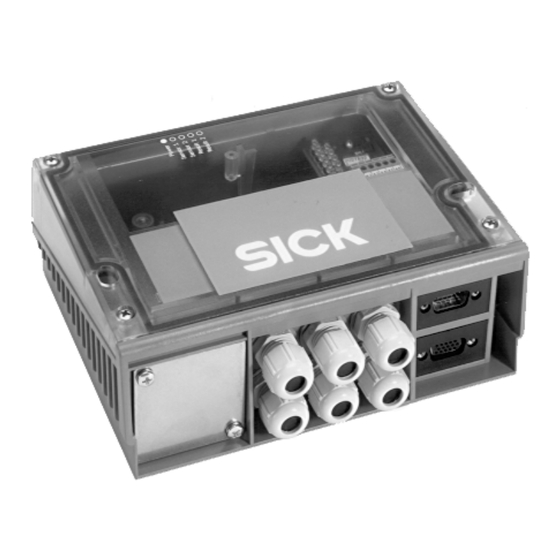
1. Produkteigenschaften
Modular aufgebautes Anschlussmodul zum Anschluss eines
■
SICK Sensors wie folgt:
- Barcodescanner CLV480, CLV490 oder CLX490 an Host, CAN-
Scanner-Netzwerk, Feldbussysteme sowie an Peripherie und
Stromversorgung
- Lasermesssystem LMS400 an Host, Peripherie und Stromver-
sorgung
Basisgerät CDM490 zur optionalen Aufnahme
■
- eines Cloning-Moduls CMC400/CMC600 für externe Speiche-
rung der Konfigurationsparameter des Barcodescanners
- eines Display-Moduls CMD400, eingebaut in Deckelvariante,
zur Anzeige von Leseergebnissen und Lesediagnosedaten des
Barcodescanners oder
- eines Power-Supply-Moduls CMP490, eingebaut in Deckel-
variante, zur Stromversorgung des Sensors aus einem Wech-
selstromnetz
- eines Feldbus-Moduls CMF400 zur Anbindung des Barcode-
scanners an PROFIBUS-DP, DeviceNet oder Ethernet TCP/IP
9-pol. D-Sub-Stecker intern, für Anschluss der ser. Aux-Schnitt-
■
stelle (RS-232) an PC zur Konfiguration/Diagnose des Sensors
Variante CDM490-0101: serielle Host- und Aux-Schnittstelle
■
zusätzlich über zwei 9-polige D-Sub-Buchsen auf Frontblende
Klemmen für Host-Schnittstelle, CAN-Bus, Schaltein- und
■
-ausgänge, Stromversorgung, Schirmung
Anschluss des Sensors über 15-polige D-Sub-HD-Stecker/
■
Buchse, Peripherie an Klemmen über Kabelverschraubungen,
Feldbus über systemabhängige Steckverbindungen (Frontblende)
Geeignet zur Stromversorgung eines Barcodescanners mit
■
Heizung durch zusätzliches, externes Netzteil
Von außen sichtbar: LEDs zur Anzeige von aktiven Schaltein- und
■
ausgängen sowie Schalterstellungen der Modulkonfiguration
Schutzart IP 65 (Variante CDM490-0101: IP 20)
■
Wartungsfrei
■
UL-zertifiziert bei Verwendung eines Class 2-Netzgeräts
■
(geprüft nach UL 1310) zur Stromversorgung
Weitere Produktinformationen, Programm „CLV-Connect":
Siehe www.sick.com
EG-Konformitätserklärung:
Auf Anforderung
8010005/RD09/2008-02
SICK
Sensor
Lesetakt
LS
Reading clock
"Sensor"
Wählbare
Funktionen
LS
Variable
"IN 0" ... IN 4"
functions
O p e r a t i n g I n s t r u c t i o n s
1. Features
Compact connection module for connecting one SICK sensor to
■
the following components:
- CLV480, CLV490 or CLX490 Bar Code Scanner to the host,
CAN Scanner Network, fieldbus systems as well as to the
peripheral equipment, and power supply
- LMS400 Laser Measurement System to the host, peripheral
equipment, and power supply
Basic device CDM490 for integrating optionally the following
■
- CMC400/CMC600 Cloning Module for saving the bar code
scanner's configuration parameters externally
- CMD400 Display Module (installed in a cover variant) for
displaying the reading results and reading diagnosis data of
the bar code scanner or
- CMP490 Power Supply Module (installed in a cover variant) for
supplying power to the sensor from an AC power line
- CMF400 Fieldbus Module for connecting the bar code scanner
to the PROFIBUS-DP, DeviceNet or Ethernet TCP/IP
9-pin internal D-Sub connector, for connecting the serial Aux
■
interface (RS 232) to a PC for configuring/diagnosing the sensor
CDM490-0101 variant: The serial host and Aux interface can
■
also be connected via two 9-pin D-Sub sockets on face plate
(front)
Terminals for host interface, CAN bus, switching inputs/outputs,
■
power supply, and shield
Connection of sensor via 15-pin D-Sub HD plug/socket, periphe-
■
ral equipment to terminals via cable glands, and fieldbus via
system depending plug-in connections on face plate (front).
Suitable for powering a bar code scanner with heater by means
■
of an additional external power supply
Externally visible LEDs for displaying active switching inputs and
■
outputs, as well as switch settings for module configuration
Enclosure rating IP 65 (CDM490-0101 variant: IP 20)
■
Maintenance-free
■
UL certificated when a class 2 power supply according to
■
UL 1310 is used
Further Product Information, "CLV-Connect" PC Program:
See www.sick.com
EC Conformity Declaration:
On request
© SICK AG · Division Auto Ident · Germany · All rights reserved
"Aux"
PC
"CAN"
CDM490-0001
CAN bus
"Host"
HOST
"Result 1"
"Result 2"
SPS/
"Result 3"
PLC
"Result 4"
V
S
1 # 8
Inhaltsverzeichnis

Verwandte Anleitungen für SICK CDM490-0001


Inhaltszusammenfassung für SICK CDM490-0001
- Seite 1 UL 1310 is used Weitere Produktinformationen, Programm „CLV-Connect“: Further Product Information, ”CLV-Connect” PC Program: Siehe www.sick.com See www.sick.com EG-Konformitätserklärung: EC Conformity Declaration: Auf Anforderung On request 8010005/RD09/2008-02 © SICK AG · Division Auto Ident · Germany · All rights reserved 1 # 8...
- Seite 2 Wichtig: gleichzeitiger Betrieb des Displays CMD400 und des Power-Supply-Moduls CMP490 nicht möglich. Important: simultaneous operation of CMD400 Display Module and CMP490 Power Supply Module not possible. 2 # 8 © SICK AG · Division Auto Ident · Germany · All rights reserved 8010005/RD09/2008-02...
-
Seite 3: Data Interfaces
Trennung durch Doppelisolation und Sicher- by means of double insulation and a safety isolating transformer heitstrafo nach IEC 742 besitzen. according to IEC 742. 8010005/RD09/2008-02 © SICK AG · Division Auto Ident · Germany · All rights reserved 3 # 8... -
Seite 4: Verdrahtung Des Cdm490
Do not extend the length of the cables! 2. Weiter mit Schritt 2 unter 5.3.2, nächste Seite. 2. Continue with Step 2 under 5.3.2 on the next page. 4 # 8 © SICK AG · Division Auto Ident · Germany · All rights reserved 8010005/RD09/2008-02... -
Seite 5: Barcodescanner Ohne Heizung
3) Class I with CMP490 power supply module and connected PE conductor (gültig bei entsprechender Geräte- 4) With SICK standard cables and closed face plate (dummy plate) on the CDM490 kennzeichnung auf dem Typenschild) 5) Without any mounting or electrical installation work, otherwise –20 °C (–4 °F) - Seite 6 Space required for connecting plugs Anschlussraum für Stecker bei optionaler Frontblende mit Steckverbindungen Space required for connecting plugs when using optional face plate with plug-in connections 6 # 8 © SICK AG · Division Auto Ident · Germany · All rights reserved 8010005/RD09/2008-02...
- Seite 7 Stromlaufplan Basiskarte/circuit diagram of main board 8010005/RD09/2008-02 © SICK AG · Division Auto Ident · Germany · All rights reserved 7 # 8...
- Seite 8 TD+ (RS 422) yellow not connected – RD+ (RS 422) grey not connected – SICK AG · Waldkirch · Germany · www.sick.com 8 # 8 © SICK AG · Division Auto Ident · Germany · All rights reserved 8010005/RD09/2008-02...