Werbung
Quicklinks
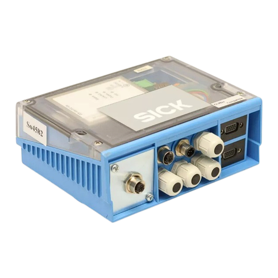
C D M 4 2 5 P R O F I N E T
CDM425-00034094
A n s c h l u s s m o d u l e
Connection Modules
E r g ä n z u n g d e r B e t r i e b s a n l e i t u n g e n
C D M 4 2 0 - 0 0 0 1
Dieses Dokument ergänzt folgende Betriebsanleitungen der
Anschlussmodule aus der Serie CDM420:
Betriebsanleitung CDM420-0001 (Artikel-Nr. 8010004, ab Stand
■
TF10, 2009-08),
Betriebsanleitung CDM420-0004 (Artikel-Nr. 8011155, ab Stand
■
S012,2009-04)
Die Betriebsanleitungen liegen dem jeweiligen CDM425 als Basis-
information bei.
1. Produkteigenschaften
Beide Anschlussmodule CDM425 dienen der Integration von SICK
Sensoren (Typen siehe 5. Technische Daten, Seite 4) in das
PROFINET und beruhen auf folgenden Basisgeräten:
CDM425-00034094: Basisgerät CDM420-0001, für 1 Sensor
CDM425-10234094: Basisgerät CDM420-0004, für 2 Sensoren
Die Einheit aus CDM425 und Sensor stellt im PROFINET IO ein Field
Device (IO-Device) mit einer IP-Adresse dar.
Abweichend vom jeweiligen Basisgerät gilt für das CDM425:
Zusätzlich integriertes PROFINET-Gateway
■
Betriebsmodus PROFINET IO
■
Von außen sichtbar: LEDs des Gateways zur Statusanzeige
■
Konfiguration des Gateways über IO-Controller (SPS) mit GSDML
■
Zusätzliche Basiskonfiguration des Gateways bei Bedarf über:
■
SICK PortVision Tool (Parameter für Ethernet-Netzwerk)
Web-Server (Parameter für RS-232-Schnittstelle)
Versorgungsspannung DC 10 ... 30 V
■
UL-zertifiziert bei Verwendung eines LPS- oder Class-2-Netzgeräts
■
(geprüft nach UL 1310) zur Stromversorgung
CDM425-00034094:
Zusätzliche M12-Buchse für PROFINET auf der Frontblende
■
CDM425-10234094:
Zusätzliche M12-Buchse für PROFINET auf der Frontblende
■
Reduktion der Kabelverschraubungen von 6 auf 4 Stück, dafür
■
M12-Buchse für CAN-Bus und M12-Stecker für Zuführung der
Stromversorgung auf der Frontseite. Ermöglicht den Aufbau eines
externen CAN-Scanner-Netzwerks als Erweiterung zu den beiden
direkt anschließbaren Sensoren in Master-Slave-Funktion. Im
CAN-Bus muss sich das CDM425 dann an einem Busende be-
finden. Für die beiden direkt angeschlossenen Sensoren ist der
8013624/UI95/2010-08
CDM425-10234094
u n d
C D M 4 2 0 - 0 0 0 4
© SICK AG · Germany · All rights reserved · Subject to change without notice · Irrtümer und Änderungen vorbehalten
Sensor
IO-
Controller
RS 232
Gateway
PROFINET
PROFINET
S u p p l e m e n t t o t h e C D M 4 2 0 - 0 0 0 1 a n d
C D M 4 2 0 - 0 0 0 4 O p e r a t i n g I n s t r u c t i o n s
This document complete the following operating instruc-
tions of the connection modules from the CDM420 serie:
CDM420-0001 Operating Instructions (part no. 8010004, from
■
issue TF10, 2009-08),
CDM420-0004 Operating Instructions (part no. 8011155, from
■
issue S012, 2009-04)
For basic information, these operating instructions are attached to
the CDM425.
1. Product Features
Both CDM425 Connection Modules are used to integrate SICK
Sensors into the PROFINET (for types see 5. Technical Data, Page
4). The modules bear on the following basic devices:
CDM425-00034094: Basic device CDM420-0001, for 1 sensor
CDM425-10234094: Basic device CDM420-0004, for 2 sensors
In PROFINET IO, the unit of CDM425 and Sensor presents a field
device with one IP Address.
Differing from the respective basic device the CDM425 provides:
Additional embedded PROFINET gateway
■
Operation mode PROFINET IO
■
Externally visible LEDs of the gateway for status indication
■
Gateway configuration via the IO Controller (PLC) with GSDML
■
If required, basic gateway configuration also via:
■
SICK PortVision Tool (Ethernet network parameters)
Web server (RS 232 interface parameters )
Power supply voltage 10 to 30 V DC
■
UL certified when a LPS or class 2 power supply unit according to
■
UL 1310 is used.
CDM425-00034094:
Additional M12 socket for PROFINET on front panel
■
CDM425-10234094:
Additional M12 socket for PROFINET on front panel
■
Reduction of cable glands from 6 to 4 pieces on front panel,
■
therefore M12 socket for CAN bus and M12 plug to connect the
power supply voltage. The CAN bus is used to connect an
external CAN Scanner Network to the CDM425. The directly
connected two sensors in master/slave mode can be extended
by further slaves. In the CAN bus the CDM425 must be located
on one end of the bus. For the directly connected two sensors
Sensor
Sensor
Sensor
...
...
CAN bus
RS 232
CDM425-
CDM425-
00034094
10234094
Gateway
Field
Field
PROFINET
Device
Device
Switch
1 # 4
Werbung

Inhaltszusammenfassung für SICK CDM425 PROFINET
- Seite 1 Für die beiden direkt angeschlossenen Sensoren ist der on one end of the bus. For the directly connected two sensors 8013624/UI95/2010-08 © SICK AG · Germany · All rights reserved · Subject to change without notice · Irrtümer und Änderungen vorbehalten 1 # 4...
- Seite 2 Network data transfer rate 10 MB Netzwerkübertragungsrate 100 MB Network data transfer rate 100 MB 2 # 4 SICK AG · Germany · All rights reserved · Subject to change without notice · Irrtümer und Änderungen vorbehalten 8013624/UI95/2010-08...
- Seite 3 DC 24 V Versorg.spg./p. s. voltage CAN Ground M12, Stecker (A-kodiert) n.c. – plug (A-type n.c. – encoded) 8013624/UI95/2010-08 © SICK AG · Germany · All rights reserved · Subject to change without notice · Irrtümer und Änderungen vorbehalten 3 # 4...
- Seite 4 Enclosure rating IP 65 not tested by UL ■ SICK AG · Waldkirch · Germany · www.sick.com 4 # 4 SICK AG · Germany · All rights reserved · Subject to change without notice · Irrtümer und Änderungen vorbehalten 8013624/UI95/2010-08...


