Inhaltsverzeichnis
Werbung
Quicklinks
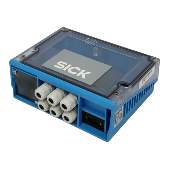
C D M 4 2 0 - 0 0 0 1
A ns chl u ssm od ul
B e t r i e b s a n l e i t u n g
1. Bestimmungsgemäße Verwendung
Modular aufgebautes Anschlussmodul (im Folgenden CDM420
■
genannt) zum Anschluss eines SICK-Identifikationssensors (im
Folgenden ID-Sensor genannt) an Host (seriell), CAN-Sensor-Netz-
werk, Feldbussysteme sowie an Peripherie und Stromversor-
gung. Der ID-Sensor ist hierzu mit einer SICK-Standardleitung
an der außen zugänglichen 15-pol. D-Sub-Dose des CDM420
anzuschließen. Über Leitungsverschraubungen und Anschluss-
klemmen werden die Stromversorgung zugeführt und Signale auf
Leitungen verteilt. Optionaler Feldbusanschluss (Gateway) über
systemabhängige Steckverbindungen auf der Frontblende. Eine
ggf. im ID-Sensor integrierte Ethernet-Schnittstelle wird nicht über
das CDM420 angeschlossen.
Unterstützte ID-Sensoren
*)
■
kamerabasierter Codeleser Lector62x, RFID-Schreib-/Lesegeräte
RFH6xx (HF) und RFU62x (UHF), Handheldscanner IDM1xx und
IDM2xx
2. Eigenschaften
Basisgerät zur optionalen Aufnahme folgender Module:
■
Parameter-Cloning-Modul CMC600 für externe Speicherung der
–
Konfigurationsparameter des ID-Sensors. Dient auch der Akti-
vierung von Betriebsarten sowie der Erweiterung des ID-Sen-
sors um jeweils 2 digitale Schaltein- und -ausgänge (bei CLV61x
bis CLV65x, Lector62x, RFH6xx und RFU62x)
Display-Modul CMD400, eingebaut in Deckelvariante, zur Anzei-
–
ge von Leseergebnissen u. Lesediagnosedaten des ID-Sensors
Feldbusmodul CMF400 zur Anbindung des ID-Sensors an PRO-
–
FIBUS-DP, DeviceNet™ oder Ethernet TCP/IP
Power-Supply-Modul CMP400 zur Stromversorgung des ID-Sen-
–
sors aus einem Wechselstromnetz.
9-pol. D-Sub-Stecker intern: Anschluss der Aux-Schnittstelle (seri-
■
ell RS-232) des ID-Sensors an PC (Konfiguration/Diagnose)
Variante CDM420-0101: zusätzlich serielle Host- und Aux-Schnitt-
■
stellen über zwei 9-polige D-Sub-Dosen auf Frontblende
Anschlussklemmen für serielle Host-Schnittstelle, CAN-Bus,
■
Schaltein- und -ausgänge, Stromversorgung, Abschirmung
Durch Deckel sichtbar: LEDs zur Anzeige von aktiven Schaltein-
■
und -ausgängen sowie Stellungen der Konfigurationsschalter
Schutzart IP 65 (Variante CDM420-0101: IP 20)
■
Betriebsumgebungstemperatur –35 °C bis +40 °C
■
UL-zertifiziert bei Verwendung eines Class-2-Netzteils
■
*) Auch geeignet für CLV42x bis CLV45x sowie ICR84x-2/ICR85x-2.
8010004/YTW9/2016-03
: Barcodescanner CLV61x bis CLV65x,
© SICK AG · Germany · All rights reserved · Subject to change without notice · Irrtümer und Änderungen vorbehalten
ID
Sensor
Licht-
schranke
(Lesetakt)
Photo reflex
"Sensor 1"
switch
(Reading clock)
"Sensor 2"
Schalter/switch
Teach-in matchcode
C onne c t ion M odu le
O p e r a t i n g I n s t r u c t i o n s
1. Intended use
Modular designed connection module (referred to as CDM420
■
below) for connecting one SICK identification sensor (referred to
as ID sensor below) to host (serial), CAN Sensor Network, fieldbus
systems, as well as to the peripheral equipment and voltage
supply. Connect the ID sensor using a SICK standard cable to
the externally accessible 15-pin D-Sub female connector of the
CDM420. Via cable glands and terminals the voltage supply is
connected and signals are distributed to cables. Optional fieldbus
connection (gateway) via system depending on plug-in connec-
tions on face plate (front). The CDM420 is not used to connect an
ID sensor with integrated Ethernet interface to the Ethernet.
Supported ID sensors
: CLV61x to CLV65x bar code scanners,
*)
■
Lector62x image-based code reader, RFH6xx (HF) and RFU62x
(UHF) RFID write/read devices, as well as IDM1xx and IDM2xx
hand-held scanners
2. Features
Basic device for integrating optionally the following modules:
■
CMC600 parameter cloning module for saving the ID sensor's
–
configuration parameters externally. Also for activation of
operating modes as well as for extension of the ID sensor with
each of two digital switching inputs and outputs (on CLV61x to
CLV65x, Lector62x, RFH6xx and RFU62x)
CMD400 display module (installed in a cover variant) for dis-
–
playing the reading results and diagnosis data of the ID sensor
CMF400 fieldbus module for connecting the ID sensor to
–
PROFIBUS-DP, DeviceNet™ or Ethernet TCP/IP
CMP400 power supply module for supplying power to the ID
–
sensor from an AC power line
9-pin internal D-Sub male connector: for connecting the Aux inter-
■
face (serial RS 232) to a PC for configuring and diagnosing the ID
sensor
CDM420-0101 variant: The serial host and Aux interfaces can
■
also be connected via two 9-pin D Sub female connector on face
plate
Terminals for serial host interface, CAN bus, switching inputs and
■
outputs, voltage supply, and shield
Externally visible LEDs for displaying active switching inputs and
■
outputs, as well as switch settings for module configuration
Enclosure rating IP 65 (CDM420-0101 variant: IP 20)
■
Operation ambient temperature –35 °C to +40 °C
■
*) Also suitable for CLV42x to CLV45x as well as ICR84x-2/ICR85x-2.
"Aux"
PC
"CAN"
CDM420-0001
CAN bus
"Host"
HOST
"Result 1"
SPS/
"Result 2"
PLC
V
S
1 # 8
Werbung
Inhaltsverzeichnis

Verwandte Anleitungen für SICK CDM420-0001


Inhaltszusammenfassung für SICK CDM420-0001
- Seite 1 *) Auch geeignet für CLV42x bis CLV45x sowie ICR84x-2/ICR85x-2. *) Also suitable for CLV42x to CLV45x as well as ICR84x-2/ICR85x-2. 8010004/YTW9/2016-03 © SICK AG · Germany · All rights reserved · Subject to change without notice · Irrtümer und Änderungen vorbehalten 1 # 8...
-
Seite 2: Montage
CMF400 Fieldbus Module Cloning-Modul CMC600 CMC600 Cloning Module Power-Supply-Modul CMP400 CMP400 Power Supply Module 2 # 8 © SICK AG · Germany · All rights reserved · Subject to change without notice · Irrtümer und Änderungen vorbehalten 8010004/YTW9/2016-03... -
Seite 3: Konfigurationselemente Und Anzeigen
*) Nr. 2056475 (mit Leitung 0,2 m) oder Nr. 2057709 (mit Leitung 0,3 m). *) No. 2056475 (with cable 0.2 m) or no. 2057709 (with cable 0.3 m). 8010004/YTW9/2016-03 © SICK AG · Germany · All rights reserved · Subject to change without notice · Irrtümer und Änderungen vorbehalten 3 # 8... - Seite 4 9-pol. Stecker „AUX“ im CDM420 anschließen CDM420-0101 variant: connect the PC alternatively to the – 4 # 8 © SICK AG · Germany · All rights reserved · Subject to change without notice · Irrtümer und Änderungen vorbehalten 8010004/YTW9/2016-03...
-
Seite 5: Stromlaufplan/Circuit Diagram
*) CLV-Setup für CLV42x to CLV45x sowie ICR84x-2/ICR85x-2. *) CLV-Setup for CLV42x to CLV45x as well as ICR84x-2/ICR85x-2. Stromlaufplan/circuit diagram 8010004/YTW9/2016-03 © SICK AG · Germany · All rights reserved · Subject to change without notice · Irrtümer und Änderungen vorbehalten 5 # 8... -
Seite 6: Aufbau, Klemmenbelegung/Design, Terminal Assignment
*) CLV-Setup für CLV42x bis CLV45x sowie ICR84x-2/ICR85x-2. *) CLV-Setup for CLV42x to CLV45x, as well as ICR84x-2/85x-2. 8010004/YTW9/2016-03 © SICK AG · Germany · All rights reserved · Subject to change without notice · Irrtümer und Änderungen vorbehalten 6 # 8... -
Seite 7: Technische Daten
IP 65 connectors) on the CDM420. 6) Without any mounting or electrical installation work, otherwise –20 °C. 8010004/YTW9/2016-03 © SICK AG · Germany · All rights reserved · Subject to change without notice · Irrtümer und Änderungen vorbehalten 7 # 8... -
Seite 8: Maßbild/Dimensioned Drawing
Space required for connectors when using optional face plate with plug-in connections SICK AG · Waldkirch · Germany For local sales offices see www.sick.com 8 # 8 © SICK AG · Germany · All rights reserved · Subject to change without notice · Irrtümer und Änderungen vorbehalten 8010004/YTW9/2016-03...