Inhaltsverzeichnis
Werbung
Verfügbare Sprachen
Verfügbare Sprachen
Quicklinks
Montage- und
Gebrauchsanweisung
Installation and
Operating Instructions
Instructions d'installation
et d'utilisation
Sole/Wasser-
Wärmepumpe für
Innenaufstellung
Bestell-Nr. / Order no. / N
WPS 50MRE
WPS 70MRE
WPS 90MRE
WPS 120MRE
Brine-to-Water
Heat Pump for
Indoor Installation
o
de commande : 452232.66.06
Pompe à chaleur
eau glycolée-eau
pour installation
intérieure
FD 8709
Werbung
Kapitel
Inhaltsverzeichnis

Verwandte Anleitungen für Buderus WPS 50MRE


Inhaltszusammenfassung für Buderus WPS 50MRE
- Seite 1 Montage- und Gebrauchsanweisung Installation and Operating Instructions Instructions d’installation et d’utilisation WPS 50MRE WPS 70MRE WPS 90MRE WPS 120MRE Sole/Wasser- Brine-to-Water Pompe à chaleur Wärmepumpe für Heat Pump for eau glycolée-eau Innenaufstellung Indoor Installation pour installation intérieure Bestell-Nr. / Order no. / N de commande : 452232.66.06...
-
Seite 3: Inhaltsverzeichnis
Inhaltsverzeichnis Bitte sofort lesen .......................... D-2 1.1 Wichtige Hinweise ..........................D-2 1.2 Gesetzliche Vorschriften und Richtlinien ....................D-2 1.3 Energiesparende Handhabung der Wärmepumpe .................D-2 Verwendungszweck der Wärmepumpe ..................D-3 2.1 Anwendungsbereich ..........................D-3 2.2 Arbeitsweise ............................D-3 Grundgerät............................ D-3 Zubehör ............................D-4 4.1 Soleverteiler............................D-4 Transport............................ -
Seite 4: Bitte Sofort Lesen
Bitte sofort lesen 1.2 Gesetzliche Vorschriften und Richtlinien 1.1 Wichtige Hinweise Die Wärmepumpe entspricht allen relevanten DIN-/VDE-Vor- schriften und EG-Richtlinien. Diese können der CE-Erklärung im ACHTUNG! Anhang entnommen werden. Die Wärmepumpe ist nicht am Holzrost befestigt. Der elektrische Anschluss der Wärmepumpe muss nach den gül- tigen VDE-, EN- und IEC-Normen ausgeführt werden. -
Seite 5: Verwendungszweck Der Wärmepumpe
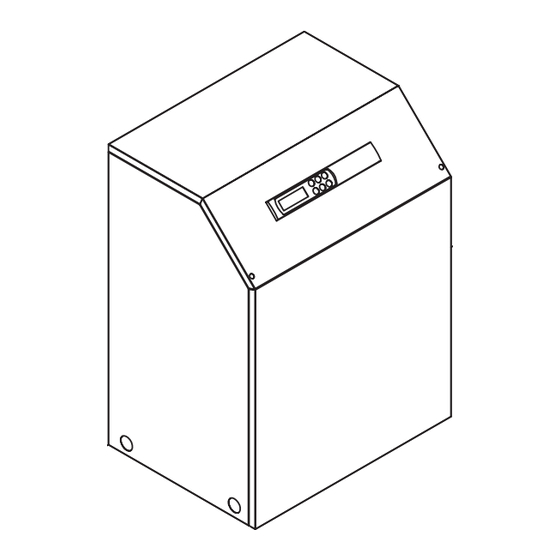
Verwendungszweck der Grundgerät Wärmepumpe Das Grundgerät besteht aus einer anschlussfertigen Wärme- pumpe für Innenaufstellung mit Blechgehäuse, Schaltblech und integriertem Regler. Im Kältekreis ist das Kältemittel R407C ein- 2.1 Anwendungsbereich gefüllt. Das Kältemittel R407C ist FCKW-frei, baut kein Ozon ab und ist nicht brennbar. Die Sole/Wasser-Wärmepumpe kann in vorhandenen oder neu Am Schaltblech sind alle für den Betrieb der Wärmepumpe not- zu errichtenden Heizungsanlagen eingesetzt werden. -
Seite 6: Zubehör
Zubehör Aufstellung 4.1 Soleverteiler 6.1 Allgemeine Hinweise Der Soleverteiler vereinigt die Kollektorschleifen der Wärmequel- Das Gerät ist grundsätzlich in Innenräumen auf einer ebenen, lenanlage zu einer Hauptleitung, welche an die Wärmepumpe glatten und waagrechten Fläche aufzustellen. Dabei sollte der angeschlossen wird. Mittels der integrierten Kugelhähne können Rahmen rundum dicht am Boden anliegen, um eine geeignete zum Entlüften einzelne Solekreise abgesperrt werden. -
Seite 7: Montage
Montage ACHTUNG! Die Sole muss mindestens zu 25 % aus einem Frostschutz auf Monoethylenglykol- oder Propylenglykolbasis bestehen und ist vor dem 7.1 Allgemein Befüllen zu mischen. An der Wärmepumpe sind folgende Anschlüsse herzustellen: 7.4 Elektrischer Anschluss Vor-/Rücklauf Soleanlage Vor-/Rücklauf Heizung An der Wärmepumpe müssen folgende elektrischen Anschlüsse hergestellt werden: Stromversorgung... -
Seite 8: Inbetriebnahme
Inbetriebnahme Störungen während Betriebes werden Wär- mepumpenregler angezeigt und können, wie in der Gebrauchs- anweisung des Wärmepumpenreglers beschrieben ist, behoben 8.1 Allgemein werden. Um eine ordnungsgemäße Inbetriebnahme zu gewährleisten, sollte diese von einem vom Werk autorisierten Kundendienst Pflege / Reinigung durchgeführt werden. -
Seite 9: Reinigung Wärmequellenseite
11 Außerbetriebnahme / 9.3 Reinigung Wärmequellenseite Entsorgung ACHTUNG! Im Wärmequelleneintritt der Wärmepumpe ist der beiliegende Bevor die Wärmepumpe ausgebaut wird, ist die Maschine span- Schmutzfänger montieren, Verdampfer gegen nungsfrei zu schalten und abzuschiebern. Umweltrelevante An- Verunreinigungen zu schützen. forderungen, in Bezug auf Rückgewinnung, Wiederverwendung und Entsorgung von Betriebsstoffen und Bauteilen gemäß... -
Seite 10: Geräteinformation
12 Geräteinformation Geräteinformation für Sole/Wasser-Heiz-Wärmepumpen Typ- und Verkaufsbezeichnung WPS 50MRE WPS 70MRE WPS 90MRE WPS 120MRE Bauform Ausführung Reversibel Reversibel Reversibel Reversibel Schutzart nach EN 60 529 IP 20 IP 20 IP 20 IP 20 Aufstellungsort Innen Innen Innen Innen... -
Seite 11: Garantieurkunde
örtlichen Versorgungsunternehmen oder unsere Montage- und Gebrauchsanweisung sowie die in den Projektie- Österreich: rungsunterlagen enthaltenen Hinweise oder Einbindungssche- Buderus Austria Heiztechnik Gesellsch.mbH men nicht beachtet worden sind oder wenn unser funktionsnot- Rennbahnweg 65 wendiges Zubehör nicht eingesetzt wurde. Durch etwa seitens A-1220 Wien des Endabnehmers oder Dritter unsachgemäß... - Seite 12 D-10...
- Seite 29 Maßbild / Dimension drawing / Schéma coté ................A-II Diagramme / Diagrams / Diagrammes..................A-III 2.1 Heizbetrieb / Heating operation / Mode chauffage WPS 50MRE ............A-III 2.2 Kühlbetrieb / Cooling operation / Mode refroidissement WPS 50MRE..........A-IV 2.3 Heizbetrieb / Heating operation / Mode chauffage WPS 70MRE ............A-V 2.4 Kühlbetrieb / Cooling operation / Mode refroidissement WPS 70MRE..........A-VI...
-
Seite 41: Last / Load / Charge
3.3 Last / Load / Charge A-XIII... -
Seite 43: Anschlussplan Kühlregler / Terminal Diagram For Cooling Controller / Schéma De Branchement Du Régulateur De Refroidissement
3.5 Anschlussplan Kühlregler / Terminal diagram for cooling controller / Schéma de branchement du régulateur de refroidissement A-XV... -
Seite 44: Legende / Legend / Légende
3.6 Legende / Legend / Légende Drahtbrücke, muss eingelegt werden, wenn kein Wire jumper, must be inserted if no blocking con- Le cavalier à fil doit être inséré en absence de dis- Sperrschütz benötigt wird tactor is required joncteur de blocage du fournisseur d’énergie Drahtbrücke, muss bei Verwendung des 2ten Sper- Wire jumper, must be removed if the 2nd disable Cavalier à... -
Seite 45: Hydraulisches Prinzipschema / Hydraulic Block Diagrams / Schéma Hydraulique
4 Hydraulisches Prinzipschema / Hydraulic block diagrams / Schéma hydraulique 4.1 Darstellung / Schematic view / Représentation schématique A-XVII... -
Seite 46: Legende / Legend / Légende
4.2 Legende / Legend / Légende Absperrventil Shutoff valve Robinet d’arrêt Sicherheitsventil Safety valve Soupape de sécurité Umwälzpumpe Circulating pump Circulateur Ausdehnungsgefäß Expansion vessel Vase d´expansion Raumtemperaturgesteuertes Ventil Room temperature-controlled valve Valve commandée par température Absperrventil mit Rückschlagventil Shutoff valve with check valve Robinet d’arrêt avec clapet anti-retour Absperrventil mit Entwässerung Shutoff valve with drainage... -
Seite 47: Konformitätserklärung / Declaration Of Conformity / Déclaration De Conformité
5 Konformitätserklärung / Declaration of Conformity / Déclaration de conformité A-XIX... - Seite 48 Heizungsfachbetrieb / Your local heating contractor / Cachet de l’installateur Deutschland Österreich BBT Thermotechnik GmbH Buderus Austria Heiztechnik GesmbH D-35573 Wetzlar Karl-Schönherr-Straße 2 www.heiztechnik.buderus.de AT-4600 Wels info@heiztechnik.buderus.de www.buderus.at office@buderus.at Schweiz Frankreich Buderus Heiztechnik AG Buderus Chauffage SAS Netzibodenstraße 36 4 rue Wilhelm Schaeffler CH-4133 Pratteln B.P.