Kemper UP-plus Einbau- Und Bedienungsanleitung
Unterputzventile
Quicklinks
Einbau- und Bedienungsanleitung
KEMPER ´UP-plus´ Unterputzventile
mit Innengewindeanschluss
with female threat connection
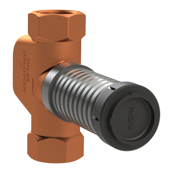
mit Pressanschluss
with press-fit connection
mit Lötanschluss
with soldered connection
mit Pressanschluss
with press-fit connection
* auch mit RV lieferbar, jedoch nicht voreinstellbar, Figur 521+526
* available also with regulating valve, without possibility of presetting, Figure 521+526
DIN-DVGW Schallschutz geprüft zum absperren, regulieren und voreinstellen.
DIN-DVGW and sound proofing for closing, regulating and presetting.
UP-Verlängerungsset
Nenngröße
DN
Nominal size
DN
Schaftdurchmesser
øS
Valve stem diameter øS
Hinweis 1:
Mit dem 2-teiligen Verlängerungsset 90 mm können die UP-Ventile nachträglich verlängert
werden.
Note 1:
With a 2-part extension 90 mm the UP valves can be extended.
Hinweis 2:
Innenoberteile können mit einem Rohrsteckschlüssel SW 17/18 x 200 problemlos durch den
Ventilschaft ausgewechselt werden.
Figur 520/560/563
Figure 520/560/563
Figur 522/524/560
Figure 522/524/560
Figur 525/560
Figure 525/560
Figur 052/056
Figure 052/056
15
18
20 25
32
15
18
20 25
32
35
35
35 43
43
35
35
35 43
43
aus Rotguss*
made of gunmetal*
aus Rotguss*
made of gunmetal*
aus Rotguss*
made of gunmetal*
aus Edelstahl
made of stainless steel
UP-Verlängerungsset Nr. 59900 Best.-Nr. B512050000004
UP extension kit
- 1 -
Order No B512050000004

Verwandte Anleitungen für Kemper UP-plus


Inhaltszusammenfassung für Kemper UP-plus
- Seite 1 Einbau- und Bedienungsanleitung KEMPER ´UP-plus´ Unterputzventile mit Innengewindeanschluss Figur 520/560/563 aus Rotguss* with female threat connection Figure 520/560/563 made of gunmetal* mit Pressanschluss Figur 522/524/560 aus Rotguss* with press-fit connection Figure 522/524/560 made of gunmetal* mit Lötanschluss Figur 525/560 aus Rotguss*...
- Seite 2 Note 2: Replacement of the inside upper parts can be carried out without problems by means of a socket key SW 17/18 x 200 through the valve stem. Hinweis 3: Beim Einlöten der Ventile mit Lötmuffe ist darauf zu achten, dass die Löttemperatur von 700° C nicht überschritten wird und das lose beiliegende Innenoberteil vorher nicht in den Wandeinbaukörper eingeschraubt wurde.
- Seite 3 3. Mit einem Schraubendreher, 3 x 200 mm, wird die M4 Voreinstellspindel innerhalb der verzahnten Hohlspindel rechts herum bis zum Anschlag eingeschraubt. Damit ist die gewünschte Drosseleinstellung festgehalten. By means of a screw driver, 3 x 200 mm, screw in the M4 presetting stem into the toothed hollow stem up to the stop.
- Seite 4 2. Sechskantschlüssel (SW 6 mm) in das Behördenoberteil (b) einführen und Ventil durch Rechtsdrehung schließen. Insert hexagonal spanner (6mm width across flats) into the authority top part (b) and close valve by turning it to the right. Gebr. Kemper GmbH + Co. KG Metallwerke Harkortstr. 5, D-57462 Olpe Tel. 02761/891-0 Fax 02761/891-175 info@kemper-olpe.de...