
Verwandte Anleitungen für Geutebruck TopLine BC Serie


Inhaltszusammenfassung für Geutebruck TopLine BC Serie
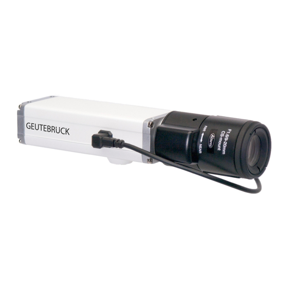
- Seite 1 TopLine BC IP Boxkamera Serie IP Box camera series Installationsanleitung Installation manual...
- Seite 3 Installationsanleitung GEUTEBRÜCK IP-Box-Kamera- Installationsanleitung Über dieses Dokument Dieses Dokument soll bei der Installation der GEUTEBRÜCK IP-Kameras in einem Netzwerk helfen. Dieses Dokument gilt für die IP-Box-Kameras, bei denen die Angabe "TopLine" einen Teil des Modellnamens bildet (Tabelle 2 auf Seite 35 zeigt eine Liste der Modelle, die in diesem Dokument beschrieben werden).
-
Seite 4: Sicherheitshinweise
Installationsanleitung Sicherheitshinweise WARNUNG Die Kamera ist nicht für die ungeschützte Verwendung in explosionsgefährdeten Bereichen ausgelegt. Wenn die Kamera in explosionsgefährdeten Bereichen zum Einsatz kommen soll, ist sie in einem entsprechenden Schutzgehäuse unterzubringen. VORSICHT Gefährliche elektrische Spannung Das Berühren von Bauteilen im Inneren der Kamera kann zum elektrischen Schlag führen. -
Seite 5: Weee-Richtlinie
Installationsanleitung HINWEIS Die Kamera ist nicht für den ungeschützten Gebrauch im Freien ausgelegt und kann durch übermäßige Feuchtigkeit oder Nässe beschädigt werden. Wenn die Kamera im Außenbereich zum Einsatz kommen soll, ist sie in einem wetterfesten Gehäuse unterzubringen. WEEE-Richtlinie Die Richtlinie 2002/96/EG (WEEE-Richtlinie) der Europäischen Union regelt die Entsorgung von Elektro- und Elektronik-Altgeräten. - Seite 6 Installationsanleitung 1 Hardware 8 Befestigungsbohrungen M3 Steckverbinder RJ-45- Netzwerk/ Factory Default- Knopf 1/4-Zoll-Standard- Stativgewinde Blenden- CS-Mount steuerung Objektiv-Adapter „ RJ-45-Netzwerk / PoE - 10/100 Ethernet-Anschluss, auch für Spannungsversorgung der Kamera über Power over Ethernet (IEEE 802.3af). „ Steckverbinder - Anschlüsse für die alternative Spannungsversorgung der Kamera, für Ein- und Ausgangskontakte und für eine serielle RS-485- Standard-Schnittstelle.
-
Seite 7: Installation Der Kamera
Installationsanleitung 2 Installation der Kamera 2.1 Installation der Hardware 1. Kamera und passendes Objektiv in einen möglichst staubfreien Raum bringen. 2. Deckel vom Objektivadapter an der Kameravorderseite abnehmen. 3. Objektiv an der Kamera anbringen: „ Wenn ein Objektiv mit CS-Mount genutzt wird, das Objektiv vorsichtig so weit wie möglich in den Adapter einschrauben. -
Seite 8: Spannungsversorgung Über Power Over Ethernet (Poe)
Installationsanleitung Spannungsversorgung über Power over Ethernet (PoE): 6. Kamera gemäß der folgenden Abbildung mit einem PoE-Netzwerk-Switch oder einem PoE-Injektor verbinden. PoE-Netzwerk-Switch Ethernet- Patchkabel PoE-Injektor Ausgang Eingang Netzwerk- Switch Ethernet- Ethernet- Patchkabel Patchkabel GEUTEBRÜCK TopLine Kameras... - Seite 9 Installationsanleitung 7. Wenn Geräte an die Pins DC-Out, I/O oder RS-485 im Steckverbinder der Kamera angeschlossen werden: a. Informationen zu Pinbelegung und Funktionen des Steckverbinders in Abschnitt 4 lesen und festlegen, auf welche Art die Geräte mit der Kamera verbunden werden sollen. b.
-
Seite 10: Spannungsversorgung Über Steckverbinder
Installationsanleitung Spannungsversorgung über Steckverbinder: 6. Sicherstellen, dass die Spannungsversorgung den in Tabelle 1 auf Seite 30 genannten Anforderungen und der Leitungsdurchmesser den Angaben auf Seite 29 entspricht. 7. Schwarze, 8-polige Weidmüller-Anschlussklemme, die mit der Kamera geliefert wurde, zur Hand nehmen. 8. - Seite 11 Installationsanleitung a. Informationen zu Pinbelegungen und Funktionen des Steckverbinders in Abschnitt 4 lesen und festlegen, auf welche Weise die Geräte mit der Kamera verbunden werden sollen. b. Geräteleitungen an die Weidmüller-Anschlussklemme anschließen. 10. Ethernet-Kabel mit der RJ-45-Buchse an der Kamera und dem Netzwerk- Switch verbinden wie in der folgenden Abbildung dargestellt.
-
Seite 12: Lokalisieren Der Kamera Im Netzwerk Und Erster
Installationsanleitung 2.2 Lokalisieren der Kamera im Netzwerk und erster Zugriff auf die Kamera ® „ Es wird vorausgesetzt, dass Windows als Betriebssystem des Rechners verwendet wird. Es wird ein Webbrowser benötigt, um auf die GEUTEBRÜCK IP-Kamera zuzugreifen. Die empfohlenen Webbrowser sind Microsoft Internet Explorer Version 8.0 oder höher und Mozilla Firefox Version 3.6 oder höher. - Seite 13 Installationsanleitung 4. Auf die Verknüpfung BIP Finder doppelklicken. Die BIP Finder-Software öffnet sich. Aktivieren Sie durch Klicken des Buttons "Baumstruktur" die Suche im Netzwerk. Der BIP Finder findet die GEUTEBRÜCK IP- Kamera(s) im Netzwerk und zeigt diese in einer Baumstruktur an. Die mit Ihrem Netzwerk verbundenen GEUTEBRÜCK IP-Kameras werden im BIP Finder-Fenster mit der Seriennummer aufgelistet.
- Seite 14 Installationsanleitung 5. Notieren Sie die IP-Adresse dieser Kamera (z. B. 169.254.112.169). Öffnen Sie die Netzwerkeinstellungen Ihres Rechners und vergeben Sie dort eine IP-Adresse im Netzwerk (169.254.112.XXX) der Kamera (siehe folgende Abbildung ). Notieren Sie sich hier ebenfalls die ursprünglichen Netzwerkeinstellungen. Bestätigen Sie mit OK.
- Seite 15 Installationsanleitung Der unten abgebildete Screenshot zeigt, wie sich der Webbrowser öffnet und auf den Surveillance Web Client in der ausgewählten Kamera zugreift. Beim ersten Zugriff auf die Kamera über den Webbrowser könnte eine Meldung erscheinen, die die Installation eines ActiveX-Steuerelements durch Klicken auf die Informationsleiste empfiehlt.
- Seite 16 Installationsanleitung 8. Der GEUTEBRÜCK Surveillance Web Client zeigt nun den Live- Bilddatenstrom der Kamera, siehe unten. Nun können Sie mit Linksklick auf den Button "Configuration" Einstellungen an der Kamera vornehmen. GEUTEBRÜCK TopLine Kameras...
- Seite 17 Installationsanleitung Es öffnet sich folgendes Kameraeinstellungsmenü: Klicken Sie auf den Menüpunkt "Network" Es öffnet sich folgendes Kontextmenü: GEUTEBRÜCK TopLine Kameras...
- Seite 18 Installationsanleitung 9. Deaktivieren Sie das Kontrollkästchen "DHCP". (Pfeil 1) Vergeben Sie nun die für die Kamera vorgesehene IP-Adresse im Bereich Ihres Netzwerks (z.B. 192.168.0.234). (Pfeil 2) Bestätigen Sie mit einem Linksklick auf den Button "Commit". (Pfeil 3) Schließen Sie die Software BIP Finder. 10.
- Seite 19 Installationsanleitung 11.Starten Sie die Software "GSCSetup" mit einem Doppelklick auf das Desktop-Icon. Doppelklicken Sie auf "Lokale Verbindungen". (Pfeil 1) Klicken Sie auf "Hardware". (Pfeil 2) GEUTEBRÜCK TopLine Kameras...
- Seite 20 Installationsanleitung Es öffnet sich die Hardwaremodul-Liste. Mit Rechtsklick auf "Hardware module list" (Pfeil 1) öffnen Sie ein Auswahlfenster. Klicken Sie hier auf "Add" [Hinzufügen]. Es öffnet sich ein zweites Auswahlfenster. Klicken Sie hier ebenfalls auf "Add". Es erscheint nun eine Liste der verfügbaren Hardwaremodule. GEUTEBRÜCK TopLine Kameras...
- Seite 21 Installationsanleitung Scrollen Sie bis zum Kamera Plugin <TOPLINE IPC> (32) und doppelklicken Sie darauf. Das ausgewählte Modul (Pfeil 1) erscheint nun als "IP-Camera Plugin 001" in der "Hardware module list" (siehe nächste Abbildung). Es kann umbenannt werden (z.B. TopLine Kamera 1). GEUTEBRÜCK TopLine Kameras...
- Seite 22 Installationsanleitung Senden Sie Ihre Auswahl mit Klick auf den Button an den Server. (Pfeil 1) Markieren Sie die Kamera (Pfeil 2) und tragen Sie die im BIP Finder eingetragene IP-Adresse Ihrer TopLine Kamera im erscheinenden Menü ein. (Pfeil 3) Senden Sie Ihre Auswahl mit Klick auf den Button an den Server.
- Seite 23 Installationsanleitung Damit Bilder Ihrer Kamera übertragen werden können, muss nun ein Medienkanal zugewiesen werden. Klicken Sie unter "General settings" auf den Menüpunkt "Media channels". (Pfeil 1) Es erscheint eine Liste der verfügbaren Medienkanäle. Durch Klick auf Add (Pfeil 2) fügen Sie einen neuen Medienkanal hinzu. Markieren Sie durch Linksklick diesen neuen Medienkanal.
- Seite 24 Installationsanleitung Nun erscheint der Videostream der Kamera (siehe nächste Abbildung). GEUTEBRÜCK TopLine Kameras...
- Seite 25 Installationsanleitung 12. Erweiterte Einstellmöglichkeiten. In den Hardwareeigenschaften können Sie weitere Einstellungen wie das Streamingverhalten (globale Einstellungen) vornehmen (siehe nach- folgende Screenshots). Bitte beachten Sie, dass hier vorgenommene Einstellungen die im Webbrowser eingestellten Kameraparameter überschreiben! GEUTEBRÜCK TopLine Kameras...
- Seite 26 Installationsanleitung Bitte beachten Sie, dass hier vorgenommene Einstellungen die im Webbrowser eingestellten Kameraparameter überschreiben! 13.Schließen Sie GSCSetup. GEUTEBRÜCK TopLine Kameras...
- Seite 27 Installationsanleitung 14. Starten Sie mit einem Doppelklick auf das Desktop-Icon GSCView. Durch Anwahl des entsprechenden Medienkanals (Pfeil 1) wird das Bild der TopLine Kamera auf den gewählten Viewer aufgeschaltet. GEUTEBRÜCK TopLine Kameras...
-
Seite 28: Firmware-Updates
Installationsanleitung 3 Firmware-Updates Um sicherzustellen, dass die Funktionalität der Kamera auf dem neuesten Stand ist, sollten Sie sich regelmäßig im Downloadbereich der GEUTEBRÜCK-Website informieren, ob es neue Dateien zum Update der Firmware gibt. Die Internetadresse lautet: www.geutebrueck.com Mit Hilfe des Surveillance Web Client können Sie sich die aktuell installierte Firmware-Version auf der Kamera anzeigen lassen und ein Firmware-Update durchführen. - Seite 29 Installationsanleitung 4 Steckverbinder Funktionen des 8-poligen Steckverbinders an der Kamerarückseite: „ Spannungsversorgung der Kamera (wenn PoE nicht genutzt wird) „ Zugriff auf I/O-Kontakte der Kamera „ Zugriff auf RS-485-Schnittstelle Der Steckverbinder an der Kamera ist als Weidmüller-Steckverbinder ausgeführt. Der empfohlene Gegenstecker ist eine 8-polige Weidmüller- Anschlussklemme (Bestellnummer 4.84940).
- Seite 30 Installationsanleitung Die Pinnummerierung und -belegungen des Steckverbinders sind unten angegeben. Die Pinbelegungen sind in Tabelle 1 auf Seite 30 im Detail beschrieben. I/O-0 I/O-1 I/O-2 RS-485 ext. RS-485 Spannungs- versorgung GEUTEBRÜCK TopLine Kameras...
- Seite 31 Installationsanleitung Beim Anklemmen der Adern an der Weidmüller-Anschlussklemme, dem Gegenstecker zum Steckverbinder, ist die im Folgenden beschriebene Methode anzuwenden. Die Adern werden in der Anschlussklemme durch Zugfedern festgehalten. Diese sind besonders fest und deswegen ist es unbedingt erforderlich, die beschriebene Methode anzuwenden, um die Adern richtig anzuklemmen.
- Seite 32 Installationsanleitung „ Aderendhülsen sind bei Litzenleitungen nicht vorgeschrieben, können aber auf Wunsch verwendet werden. Wenn Aderendhülsen verwendet werden, müssen diese einen Querschnitt zwischen 0,13 mm 0,34 mm aufweisen. Pin #: 1 Funktion: Masse Beschreibung: Masse für die Spannungsversorgung der Kamera, I/O-0, I/O-1, I/O-2 und die serielle Schnittstelle RS-485.
- Seite 33 Installationsanleitung Pin #: 4, 6, 8 Funktion: entsprechen I/O-0, I/O-1 und I/O-2 Beschreibung: Jedre I/O-Kontakt kann eingestellt werden, um als Ein- oder Ausgang zu arbeiten. Die Funktionswahl und ob eine bestimmte I/O-Schnittstelle als Eingang oder Ausgang arbeitet, werden bei der Einstellung der Kameraparameter vorgenommen (Weitere Informationen zur Einstellung der Kameraparameter, siehe Benutzerhandbuch).
- Seite 34 Installationsanleitung (Fortführung der Beschreibung der Pins 4, 6, 8 von vorheriger Seite.) Für jede I/O-Schnittstelle, die als Ausgang geschaltet ist: Im Schaltschema auf Seite 34 wurden I/O-0 und I/O-1 eingestellt, um als Ausgänge zu arbeiten. Ein Ausgang verfügt über einen Transistor mit offenem Kollektor, der, wie im Schaltschema gezeigt, mit Masse verbunden ist.
- Seite 35 Installationsanleitung Pin #: 5 Funktion: RS-485 A+ Beschreibung: Pin A+ für eine Standard RS-485-Verbindung. Pin #: 7 Funktion: RS-485 B- Beschreibung: Pin B- für eine Standard RS-485-Verbindung. Tabelle 1: Pinbelegung Steckverbinder Standardmäßig ist die Schnittstelle I/O-0 als Ausgang mit vom Nutzer einstellbarer Funktion und die Schnittstellen I/O-1, I/O-2 sind als Eingänge mit Überwachungsfunktion eingestellt.
- Seite 36 Installationsanleitung +12 bis +24 Kamera Ext. Spannungsversorgung DC Out I/O-0 (als Ausgang geschaltet) max. Relais I/O-1 (als Ausgang geschaltet) Relais Schalter I/O-2 (als Eingang geschaltet) Gerät Masse (Gnd) RS-485 Gnd RS-485 A+ RS-485 A+ RS-485 B- RS-485 B- GEUTEBRÜCK TopLine Kameras...
-
Seite 37: Technische Spezifikationen
Installationsanleitung 5 Technische Spezifikationen Bestell - Name Beschreibung Nummer 5.02800 TopBC-1113 GEUTEBRÜCK TopLine 720p, 1/3'' CMOS Box-IP-Kamera mit H264CCTV und Progressive Scan; für DC-Objektive und Niederspannungs- oder PoE-Betrieb 5.02802 TopBC-1118 GEUTEBRÜCK TopLine 1080p, 1/3'' CMOS Box-IP- Kamera mit H264CCTV und Progressive Scan; für DC- Objektive und Niederspannungs- oder PoE-Betrieb 5.02810 TopBC-2113 GEUTEBRÜCK TopLine 720p, 1/3"... - Seite 38 Installationsanleitung Bestell - Name Beschreibung Nummer 5.02840 TopBC-1183 GEUTEBRÜCK TopLine 1,3 Megapixel 1/3" CCD Box-IP- Kamera mit H264CCTV und Progressive Scan; für DC- Objektive und Niederspannungs- oder PoE-Betrieb 5.02842 TopBC-1188 GEUTEBRÜCK TopLine 2 Megapixel 1/1,8" CCD Box-IP- Kamera mit H264CCTV und Progressive Scan; für DC- Objektive und Niederspannungs- oder PoE-Betrieb 5.02845 TopBC-2183 GEUTEBRÜCK TopLine 1,3 Megapixel...
- Seite 39 Installation Guide GEUTEBRÜCK IP Box Camera Installation Guide About This Document This document is intended to help you install your GEUTEBRÜCK IP Cameras on a network. This document applies to IP Box Cameras that include the designation "TopLine" as part of their model name (see Table 2 on page 35 for a list of the models covered by this document).
- Seite 40 Installation Guide Precautions WARNING The camera is not designed for unprotected use in an explosive atmosphere. If you use the camera in an explosive atmosphere, it must be enclosed within an appropriate environmental housing. CAUTION Electrical Shock Hazard Touching the camera’s internal components may result in an electrical shock.
-
Seite 41: Weee Directive
Installation Guide NOTICE The camera is not designed for unprotected outdoor use and can be damaged by excessively damp or wet conditions. If you are using the camera outdoors, you should mount the camera in a weatherproof housing. WEEE Directive The European Union has enacted Directive 2002/96/EC on Waste Electrical and Electronic Equipment (the WEEE Directive). -
Seite 42: Hardware Overview
Installation Guide 1 Hardware Overview Terminal M3 Mounting Holes (x8) Connector RJ-45 Network/ Factory Default Button 1/4’’ Standard Tripod Mount DC Iris Control CS-mount Lens Adapter „ RJ-45 Network / PoE - Provides a 10/100 Ethernet connection and can be used to connect Power over Ethernet (IEEE 802.3af) to the camera. -
Seite 43: Installing The Camera
Installation Guide 2 Installing the Camera 2.1 Hardware Installation 1. Take the camera and an appropriate lens and move to an environment that is as dust free as possible. 2. Remove the cap from the lens adapter on the front of the camera. 3. - Seite 44 Installation Guide If camera power will be supplied via Power over Ethernet (PoE): 6. Connect the camera to a PoE network switch or to a PoE injector as shown below. PoE Network Switch Ethernet Patch Cable PoE Injector Network Switch Ethernet Ethernet Patch...
- Seite 45 Installation Guide 7. If you will be connecting devices to the DC Out, I/O, or RS-485 pins in the camera’s terminal connector: a. Read the information in Section 4 regarding the pin numbering and pin functionality for the terminal connector and determine how you wish to connect the devices to the camera.
- Seite 46 Installation Guide If camera power will be supplied via the terminal connector: 6. Make sure that your power supply meets the camera power requirements stated in Table 1 on page 30 and the wire size requirements stated on page 29. 7.
- Seite 47 Installation Guide 10. Connect an Ethernet cable to the RJ-45 connector on the camera and to your network switch as shown below. Network Switch Ethernet Patch Cable Weidmüller Plug Pin 1 + DC In 11. Insert the Weidmüller plug into the terminal connector on the back of the camera.
- Seite 48 Installation Guide 2.2 Locating the Camera on Your Network and Making Initial Camera Access „ The location procedure assumes that your camera is on the same network ® subnet as your PC and that you have a Windows operating system on your PC.
- Seite 49 Installation Guide 4. Double click on the BIP Finder shortcut. The BIP Finder software opens. Click on the Button "Treeview" to activate the network camera search. The BIP Finder will locate the GEUTEBRÜCK IP Camera(s) on your network, and will display them in a tree format. The GEUTEBRÜCK IP Cameras connected to your network will be listed in the BIP Finder window by serial number.
- Seite 50 Installation Guide 5. Please note the IP-adress of this camera (e.g. 169.254.112.169). Open the Network Configuration window (see following figure) and change the IP-adress of your computer to an IP-adress in the subnet of the camera (169.254.112.XXX). Also note your primary network configuration. Confirm with click on Button OK.
- Seite 51 Installation Guide the Surveillance Web Client in the selected camera as shown below. Assuming that this is the first time you are accessing the camera via the web browser, you may see a message asking you to click on the Information Bar to allow installation of an ActiveX control.
- Seite 52 Installation Guide d. The Surveillance Web Client will display a live stream from the camera as shown below. With click on the Button "Configuration" (1) you can change the TopLine camera settings. The following configuration menu opens: GEUTEBRÜCK TopLine cameras...
- Seite 53 Installation Guide Please click on the menu item "Network" The following context menu opens: GEUTEBRÜCK TopLine cameras...
- Seite 54 Installation Guide 7. Disable the check box "DHCP". (1) Change the camera’s IP-adress to the designated IP-adress in the range of your network (e.g. 192.168.0.234). (2) Confirm with click on the Button "Commit". (3) Close the software BIP Finder. 8. Open the Network Configuration window of your computer and return to your primary network configuration.
- Seite 55 Installation Guide 9. Start the software "GSCSetup" by double clicking on the desktop icon. Double click on "local connections". (1) Click on "Hardware". (2) GEUTEBRÜCK TopLine cameras...
- Seite 56 Installation Guide The hardware module list will open. With a right click on "Hardware module list" (1) you will open a pop up window. Click on button "Add". A second pop up window appears. Click here also on Button "Add". A list with the available hardware modules opens (see following figure).
- Seite 57 Installation Guide Please scroll to the camera Plugin <TOPLINE IPC> (32) and doubleclick on it. The chosen module (1) appears as "IP-Camera Plugin 001" in the "Hardware module list" (see next figure). The name can be changed (e.g. TopLine Camera 1). GEUTEBRÜCK TopLine cameras...
- Seite 58 Installation Guide Click the icon on the toolbar to send your choice to the server (1). Click on the camera’s module channel (2) and insert the new IP-adress of your TopLine camera in the connection menu (3). Click the icon on the toolbar again to send your modifications to the server (1).
- Seite 59 Installation Guide 10. Now you must assign a media channel to transmit the camera’s pictures. Please click in "General settings" on the menu item "Media channels" (1). A list of the available media channels appears. Click the icon "Add" (2) on the toolbar to add a new media channel. Mark the new media channel with click.
- Seite 60 Installation Guide Now the camera’s picture stream appears in the viewer (see next figure). GEUTEBRÜCK TopLine cameras...
- Seite 61 Installation Guide 11. Advanced configuration. In the hardware configuration you can make advanced settings like the streaming behaviour (see following screenshots). Please note, that the configurations made here will overwrite the webbrowser configurations! GEUTEBRÜCK TopLine cameras...
- Seite 62 Installation Guide Please note, that the configurations made here will overwrite the webbrowser configurations! 12. Close the GSCSetup software. GEUTEBRÜCK TopLine cameras...
- Seite 63 Installation Guide 13. Start the GSCView software with a double click on the desktop icon GSCView. By click on the camera’s media channel (1) the camera’s videostream will be shown on the selected viewer. GEUTEBRÜCK TopLine cameras...
- Seite 64 Installation Guide 3 Firmware Updates To ensure that your camera’s functionality is up to date, you should periodically check the Downloads section of the GEUTEBRÜCK website to see if a firmware update file is available. The website address is: www.geutebrueck.com You can use the Surveillance Web Client to view the current firmware version on a camera and to perform a firmware update.
- Seite 65 Installation Guide 4 The Terminal Connector The 8-pin terminal connector on the back of the camera can be used to: „ provide power to the camera (when PoE is not used) „ access the camera’s I/O ports „ access the camera’s RS-485 connection The terminal connector on the camera is a Weidmüller header.
- Seite 66 Installation Guide The pin numbering and assignments for the terminal connector are as illustrated below. The pin assignments are described in more complete detail in Table 1 on page 30. I/O-0 I/O-1 I/O-2 Alt. RS-485 RS-485 Camera Power GEUTEBRÜCK TopLine cameras...
- Seite 67 Installation Guide When inserting wires into the Weidmüller plug that mates with the terminal connector, you must use the technique described below. The spring clamps used to hold the wires in the plug are exceptionally strong, and you must use this technique to properly insert wires.
- Seite 68 Installation Guide Pin #: 1 Function: Ground Description: Ground for camera power, I/O-0, I/O-1, I/O-2, and the RS-485 serial port. Pin #: 2 Function: DC Out Description: DC Out supplies +5.0 VDC and can be used to power a small device such as a relay as illustrated in the schematic drawing on page 34.
- Seite 69 Installation Guide Pin #: 4, 6, 8 Function: I/O-0, I/O-1, and I/O-2 respectively Description: Each I/O port can be set to operate either as an input or as an output. The choice of whether a particular I/O port will operate as an input or an output and how it will function is made by setting camera parameters (see the camera user’s manual for details about setting camera parameters).
- Seite 70 Installation Guide (Pin 4, 6, 8 description continued from the previous page.) For any I/O port set as an output: In the schematic drawing on page 34, I/O-0 and I/O-1 have been set to operate as outputs. An output port employs an open collector transistor connected to ground as shown in the schematic.
- Seite 71 Installation Guide Pin #: 5 Function: RS-485 A+ Description: A+ pin for a standard RS-485 connection. Pin #: 7 Function: RS-485 B- Description: B- pin for a standard RS-485 connection. Table 1: Terminal Connector Pin Assignments By default, the I/O-0 port is set as an output with its function set to user settable and the I/O-1 and I/O-2 ports are set as inputs with their function set to monitor.
- Seite 72 Installation Guide +12 to +24 Camera Alt. Camera Power DC Out I/O-0 (Set as an output) Relay I/O-1 (Set as an output) Relay Switch I/O-2 (Set as an input) Device RS-485 Gnd RS-485 A+ RS-485 A+ RS-485 B- RS-485 B- GEUTEBRÜCK TopLine cameras...
-
Seite 73: Basic Specifications
Installation Guide 5 Basic Specifications Bestell - Name Beschreibung Nummer GEUTEBRÜCK TopLine 720p, 1/3" CMOS box IP camera 5.02800 TopBC-1113 with progressive scan; for DC lenses and low voltage or PoE operation GEUTEBRÜCK TopLine 1080p, 1/3" CMOS day/night box 5.02802 TopBC-1118 IP camera with H264CCTV and progressive scan for DC lenses and low voltage or PoE operation... - Seite 74 Installation Guide Bestell - Name Beschreibung Nummer GEUTEBRÜCK TopLine 1.3 Mega pixel 1/3" CCD box IP 5.02840 TopBC-1183 camera with H264CCTV and progressive scan; for DC lenses and low voltage or PoE operation GEUTEBRÜCK TopLine 2 Mega pixel 1/1.8" CCD box IP 5.02842 TopBC-1188 camera with H264CCTV and progressive scan;...
- Seite 76 Technische Änderungen und Liefermöglichkeiten vorbehalten Technical alternations reserved GEUTEBRÜCK GmbH Im Nassen 7-9 | D-53578 Windhagen | Tel. +49 (0)2645 137-0 | Fax-999 E-mail: info@geutebrueck.com | Web: www.geutebrueck.com...