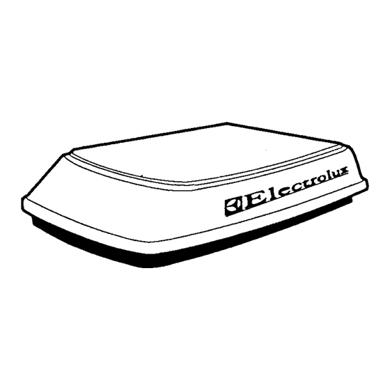
Electrolux CAL61.401 Einbau- Und Betriebsanweisung
Klimagerate zur dachmontage an wohnwagen
Inhaltsverzeichnis
Verfügbare Sprachen
Verfügbare Sprachen
INSTRUCTIONS D'INSTALLATION ET DE FONCTIONNEMENT
TAKMONTERAD LUFTKONDITIONERING FOR HUSVAGNAR
MOD. CAL61.401, CAL61.501 AND CAL136.303
IMPORTANT INSTRUCTIONS MUST STAY WITH UNIT OWNER - READ CAREFULLY.
THIS UNIT MUST BE SERVICED BY AN AUTHORIZED SERVICEMAN. MODIFICATION OF THE APPLIANCE CAN
BE EXTREMELY HAZARDOUS AND COULD LEAD TO SERIOUS INJURY OR DEATH.
WICHTIGE HINWEISE, DIE SICH IM BESITZ DES WOHNWAGENINHABERS BEFINDEN MUSSEN - BITTE
SORGFALTIG DURCHLESEN.
DER SERVICE AN DIESER EINHEIT MUSS VON EINEM HIERZU BEFUGTEN SERVICE-TECHNIKER AUSGEFUHRT
W E R D E N . EINE ABANDERUNG DES GERATS KANN AUSSERORDENTLICH GEFAHRLICH SEIN UND ZU
ERNSTHAFTEN VERLETZUNGEN ODER SOGAR ZUM TODE FUHREN.
LE CONTENU DE CETTE NOTICE EST TRES IMPORTANT, AUSSI L'UTILISATEUR DE L'APPAREIL DOIT-IL EN
POSSEDER UN EXEMPLAIRE ET LE LIRE ATTENTIVEMENT.
LES INTERVENTIONS SUR L'APPAREIL DOIVENT ETRE UNIQUEMENT EFFECTUEES PAR UN TECHNICIEN
AGREE. L'EQUIPEMENT DE DOIT FAIRE L'OBJET D'AUCUNE MODIFICATION, CE QUI POURRAIT EN EFFET SE
REVELER EXTREMEMENT DANGEREUX, SINON MEME PROVOQUER UN ACCIDENT GRAVE OU MORTEL.
VIKTIGA ANVISNINGAR: SKALL ALLTID MEDOLJA AGGREGATET OCH NOGGRANT LASAS AV AGAREN
SERVICE P A
D
E T T A
UTRUSTNINGEN KAN VARA YTTERST FARLIGA OCH LEDA TILL ALLVARLIGA OLYCKOR ELLER DODSFALL.
QUESTE ISTRUZIONI IMPORTANT1 DEVON0 ESSERE CONSEGNATE AL PROPRIETARIO DELL'UNITA.
QUESTA UNITA DEVE ESSERE RIPARATA DA UN TECNICO QUALIFICATO. LE MODIFICHE POSSONO ESSERE
ESTREMAMENTE PERICOLOSE E POSSONO CAUSARE LESIONI GRAVE 0 MORTE.
Form No. 3106846.003 10/95
1995 The Dometic Corp.
LaGrange, IN 46761
INSTALLATION & OPERATING INSTRUCTIONS
FOR CARAVAN ROOF MOUNT AIR CONDITIONERS
EINBAU-UND BETRIEBSANWEISUNGEN FUR
KLIMAGERATE ZUR DACHMONTAGE AN WOHNWAGEN
POUR CLIMATISEURS POUR CARAVANE
MONTERINGS- OCH BRUKSANVISNING
ISTRUZIONI PER L'INSTALLAZIONE E L'USO
DEL CONDIZIONATORE D'ARIA DA TETTO DI CARAVAN
AGGREGAT
A
ENDAST UTFORAS
F
R
CAL61.501
OPERATING INSTRUCTIONS ON PAGES . . . . . . . . . . . . . . . . .2-3
D
BETRIEBSANWEISUNGEN AUF DEN SEITEN . . . . . . . . . . . . .4-5
F
INSTRUCTIONS DE FONCTIONNEMENT AUX PAGES
IT
ISTRUZIONI PER L'USO NELLE PAGINE
WARNING
ACHTUNG
ATTENTION
VARNING
AUKTORISAD MONTOR. ANDRINGAR
A V
ATTENZIONE
... .
.6-7
................. .10-1
1
A V
Inhaltsverzeichnis

Verwandte Anleitungen für Electrolux CAL61.401


Inhaltszusammenfassung für Electrolux CAL61.401
-
Seite 4: Allgemeine Informationen
3. BEDIENUNGSANLEITUNG 1. ALLGEMEINE INFORMATIONEN A . KUHLBETRIEB TECHNISCHE DATEN Stellen Sie den Temperatur-Einstellhebel auf den gewunschten Temperaturpegel. 61.401 Modellbezeichnung 136.303 61.501 Stellen Sie den Geblasedrehzahlschalter auf die Nennleistung (kW) Position, die lhrem Komfortbedarf am besten 220-240V, 50 Hz., einphasig Anschlusspannung entspricht: Stromaufnahme beiVollast... -
Seite 5: Besondere Eigenschaften
C. BESONDERE EIGENSCHAFTEN Wenn der Thermostat fur: den Heizung/AUS/Kuhlung-Schalter sich auf der Der Hersteller dieses Klimagerats ist nicht verantwortlich AUS-oder HEIZUNGS-Position befindet fur Schaden, die durch Feuchtigkeitskondensation an Decken oder anderen Oberflachen verursacht werden. Luft der Aujomat/WElN-Schalter auf der EIN-Position enthalt Feuchtigkeit, und diese Feuchtigkeit neigt dazu, steht, sich auf kalten Flachen zu kondensieren.