Inhaltsverzeichnis
Werbung
Verfügbare Sprachen
Verfügbare Sprachen
Quicklinks
EGEA TECH
200 HT - 260 HT
IT - MANUALE D'USO, INSTALLAZIONE E MANUTENZIONE
ES - MANUAL DE USO, INSTALACIÓN Y MANTENIMIENTO
EN - USER, INSTALLATION AND MAINTENANCE MANUAL
PT - MANUAL DE USO, INSTALAÇÃO E MANUTENÇÃO
FR - MANUEL D'UTILISATION, INSTALLATION ET ENTRETIEN
DE - HANDBUCH FÜR BETRIEB, INSTALLATION UND WARTUNG
NL - BEDIENINGS-, INSTALLATIE- EN ONDERHOUDSHANDLEIDING
Werbung
Inhaltsverzeichnis
Fehlerbehebung

Verwandte Anleitungen für Ferroli EGEA TECH 200 HT


Inhaltszusammenfassung für Ferroli EGEA TECH 200 HT
- Seite 1 EGEA TECH 200 HT - 260 HT IT - MANUALE D’USO, INSTALLAZIONE E MANUTENZIONE ES - MANUAL DE USO, INSTALACIÓN Y MANTENIMIENTO EN - USER, INSTALLATION AND MAINTENANCE MANUAL PT - MANUAL DE USO, INSTALAÇÃO E MANUTENÇÃO FR - MANUEL D’UTILISATION, INSTALLATION ET ENTRETIEN DE - HANDBUCH FÜR BETRIEB, INSTALLATION UND WARTUNG NL - BEDIENINGS-, INSTALLATIE- EN ONDERHOUDSHANDLEIDING...
-
Seite 2: Inhaltsverzeichnis
SOMMARIO AVVERTENZE DI SICUREZZA ....................4 GLOSSARIO DELLA TERMINOLOGIA ..............36 DISPOSITIVI DI PROTEZIONE INDIVIDUALE ............36 GENERALITÀ ........................10 RUMORE ......................36 DESTINATARI DEL MANUALE ................10 VIBRAZIONI ......................36 GUIDA AL MANUALE ...................11 RISCHI RESIDUI ....................36 2.2.1 Fornitura e conservazione del manuale ..........11 MOVIMENTAZIONE E TRASPORTO ...................37 2.2.2 Aggiornamenti ..................11 MOVIMENTAZIONE DELL’IMBALLO ..............38... -
Seite 3: Identificazione Dell'apparecchiatura
ITALIANO Lingua originale del Fabbricante. Gentile Cliente, CONSERVARE PER FUTURE CONSULTAZIONI. grazie per aver scelto un prodotto FERROLI. DATI DEL FABBRICANTE La nostra azienda, da sempre attenta alle problematiche am- FERROLI S.p.A. bientali, ha utilizzato per la realizzazione dei propri prodotti,... -
Seite 4: Avvertenze Di Sicurezza
E L’INSTALLAZIONE” a pagina Il manuale è fornito in formato cartaceo; tut tavia è disponibile nella versione digitale sca ricabile dal sito www.ferroli.com selezio In fase di progettazione e costru nando il prodotto acquistato. zione degli impianti vanno rispet... - Seite 5 EGEA TECH 200 HT - 260 HT Per il corretto funzionamento Questo prodotto è progettato per dell’apparecchiatura la pressio essere utilizzato a un’altitudine ne dell’acqua in entrata deve es massima di 2000 m. ATTENZIONE ATTENZIONE sere: massimo 0,7 MPa (7 bar); ...
- Seite 6 EGEA TECH 200 HT - 260 HT corretto funzionamen Collegare l’apparecchiatura ad to dell’apparecchiatura è indi un efficiente impianto di messa a spensabile installare sull’entrata ATTENZIONE terra. dell’acqua fredda una valvola di ATTENZIONE sicurezza da 0,7 MPa (7 bar, non fornita).
-
Seite 7: Uso Scorretto Ragionevolmente Prevedibile
EGEA TECH 200 HT - 260 HT ► USO PREVISTO DAL FABBRICANTE Il fabbricante declina ogni re sponsabilità per eventuali danni Definizione provocati dalla mancata messa Pompa di calore ad aria per produzione di acqua calda sanitaria ATTENZIONE a terra dell’apparecchiatura op pure dovuti ad anomalie dell’ali... - Seite 8 EGEA TECH 200 HT - 260 HT ► PERICOLO DI MORTE A CAUSA DEL- NOTA BENE! Il fabbricante declina ogni re LE MODIFICHE AL PRODOTTO O sponsabilità nel caso di utilizzi diversi da ALL’AMBIENTE DI INSTALLAZIONE quello per cui l’apparecchiatura è stata pro •...
- Seite 9 EGEA TECH 200 HT - 260 HT Il refrigerante non deve essere rilasciato nell’atmosfera. Prima di smaltire l’apparecchiatura il refrigerante in essa conte- nuto deve essere recuperato in un contenitore adatto per essere riciclato o smaltito ai sensi delle norme vigenti. Qualsiasi intervento sull’appa...
-
Seite 10: Generalità
EGEA TECH 200 HT - 260 HT DESTINATARI DEL MANUALE ISTRUZIONI PER: Esso è rivolto sia all’installatore specializzato (installatori – ma- nutentori) che all’utente finale. Per distinguere il contenuto del manuale in base alle caratteri- TECNICO ESPERTO / ASSISTENZA UTILIZZATORE stiche del destinatario (utilizzatore e tecnico esperto), le istru- TECNICA DEL FABBRICANTE zioni sono così... -
Seite 11: Guida Al Manuale
2.2.1 Fornitura e conservazione del manuale cante. Il manuale è fornito in formato cartaceo; tuttavia è disponibile nella versione digitale scaricabile dal sito www.ferroli.com se- lezionando il prodotto acquistato. Il manuale deve essere conservato per i futuri riferimenti fino allo smantellamento dello stesso. -
Seite 12: Conformità Ai Regolamenti Europei
EGEA TECH 200 HT - 260 HT CONFORMITÀ AI REGOLAMENTI EUROPEI tanto non ci si assume alcuna responsabilità per la corrispon- denza totale. La presente pompa di calore è un prodotto destinato all’uso Nell’interesse del perfezionamento tecnico, ci riserviamo il di- domestico conforme alle seguenti direttive europee: ritto di effettuare modifiche costruttive o dei dati tecnici in qual- siasi momento. -
Seite 13: Pulizia Generale E Del Pannello Di Controllo
EGEA TECH 200 HT - 260 HT 3.2.1 Pulizia generale e del pannello di controllo Periodicità: Attrezzatura da Periodicità: utilizzare ANNUALE MENSILE TECNICO ESPERTO / Panno morbido ed UTILIZZATORE ASSISTENZA TECNICA (o in condizioni di DEL FABBRICANTE UTILIZZATORE asciutto sporcizia evidente) Per garantire il permanere delle caratteristiche di funzionalità... -
Seite 14: Descrizione Dell'interfaccia Utente
EGEA TECH 200 HT - 260 HT DESCRIZIONE DELL’INTERFACCIA UTENTE visualizzata la versione firmware del display. Durante il normale funzionamento del prodotto le tre cifre del display mostrano la temperatura dell’acqua in °C, misurata con la sonda acqua superiore. Invece, durante la modifica del set-point la temperatura sul di- splay è... -
Seite 15: Standby
EGEA TECH 200 HT - 260 HT 3.5.3 Standby 3.6.3 ELECTRIC In modalità standby sul display viene visualizzata la scritta Stb. Sul display viene visualizzato il simbolo “HEATER“ In questa modalità la pompa di calore è spenta, ma rimangono Con questa modalità viene utilizzata soltanto la resistenza elet- attive (se precedentemente abilitate) tutte le funzioni ausiliarie trica all’interno dei limiti di funzionamento del prodotto ed è... -
Seite 16: Funzionalita' Cascata
EGEA TECH 200 HT - 260 HT FUNZIONALITA’ CASCATA COME ACCEDERE AL MENU UTENTE E IN STALLATORE Con il termine cascata si vuole indicare un gruppo di scaldac- qua che funzionano assieme, all’interno del quale viene identi- Oltre alla possibilità di cambiare il set-point, da display è pos- ficato un solo Master e più... -
Seite 17: Utilizzo Dei Tasti Durante La Navigazione Nei Menù
EGEA TECH 200 HT - 260 HT 3.9.1 Utilizzo dei tasti durante la navigazione nei menù Successivamente si potranno scegliere i giorni su cui imposta- re la programmazione secondo i valori in tabella: Azione Simbolo All’interno di un menù o sottomenù Durante la modifica di un parametro Parametro Descrizione... -
Seite 18: Menu Fan - Impostazione Modalita' Fan E Silenziosa
EGEA TECH 200 HT - 260 HT Eseguire la stessa procedura per le fascie da 2 (d1b) a 6 3.9.5 Menu En ENERGY MONITORING (d1F), quindi ripetere per i successivi giorni (d_2=Martedì, La funzione Energy Monitoring con d_3=Mercoledì, d_4=Giovedì, d_5=Venerdì, d_6= Sabato, sente attraverso algoritmi proprietari d_7=Domenica). -
Seite 19: Menu Rst - Reset
EGEA TECH 200 HT - 260 HT NOTA: Parametro Descrizione Unità di misura Livello * : per la lettura corretta di questo parametro il valore risul Energia termica mensile U / I tante dalle 3 schermate va diviso per 10. Energia termica annuale U / I Es. -
Seite 20: Menu Phv - Funzionalità Evu - Funzionalità Fotovoltaico
EGEA TECH 200 HT - 260 HT Livello: U=menù utente - I=menù installatore Parame- Unità di Descrizione default min Livello Misura Isteresi sonda superiore accensione NOTA: se abilitata e attiva, questa funzionalità ha la priorità resistenza elettrica (solo per modo °C Electric e Booster) sulla funzionalità... -
Seite 21: Menu Sol - Parametri Solare Termico
EGEA TECH 200 HT - 260 HT Se ad esempio offset è pari a 20°C e il setpoint = 50°C il setpoint mendo il tasto “SET” compariranno i valori “G01” e “G02”. sarà 50+20=70°C. In ogni caso per impostazione di fabbrica il Parame- Unità... -
Seite 22: Menu Rec - Impostazione Pompa Di Ricircolo
EGEA TECH 200 HT - 260 HT dotato infatti di una funzionalità, chiamata ANTI-LEGIONELLA, Parametri: che, se abilitata, permette di effettuare cicli automatici di di- L01: da questo parametro è possibile abilitare o disabilitare la sinfezione, portando la temperatura dell’acqua all’interno del funzionalità... -
Seite 23: Menu Cas - Cascata
EGEA TECH 200 HT - 260 HT NELLA abbia effetto. sto il livello di funzionamento massimo h04: parametro che rappresenta l’intervallo di tempo, espresso NOTA: i parametri c04, c05, c06, c07, c08 vanno impostati solo in numero di giorni, tra due cicli di ANTI-LEGIONELLA sull’unità... -
Seite 24: Altre Funzionalità
7 terza schermata A seconda che si dispone di uno smartphone con sistema ope- rativo Android oppure iOS , mediante l’App dedicata. ® ® Scaricare ed installare l’App "Ferroli Home" fig. 8 quarta schermata cod. 3540000420 - Rev. 03 - 09/2023... -
Seite 25: Registrazione Utente
Avviare l’App "Ferroli Home" dal proprio smartphone premen- do sull’icona come sopra riportata. Registrazione utente Per utilizzare per la prima volta l’applicazione "Ferroli Home" è necessaria la registrazione dell’utente: creare un nuovo ac- count → inserire il numero di cellulare/l’indirizzo e-mail → inse- rire il codice di verifica e impostare la password →... - Seite 26 EGEA TECH 200 HT - 260 HT 4. Termini e condizioni d’uso 6. Pin fig. 14 fig. 16 5. Password 7. Registrazione completata fig. 15 fig. 17 cod. 3540000420 - Rev. 03 - 09/2023...
- Seite 27 EGEA TECH 200 HT - 260 HT 8. Homepage vuota. 10. Permesso fotocamera. fig. 18 fig. 20 9. Metodo di associazione 11. Data matrix fig. 19 fig. 21 cod. 3540000420 - Rev. 03 - 09/2023...
- Seite 28 EGEA TECH 200 HT - 260 HT 12. Tipo e modello dispositivo. 14. Attivazione bluetooth e generazione PIN di autenticazione. fig. 22 fig. 24 15. Ricerca bluetooth. 13. Permesso bluetooth smartphone fig. 25 fig. 23 cod. 3540000420 - Rev. 03 - 09/2023...
- Seite 29 EGEA TECH 200 HT - 260 HT 16. Dispositivi bluetooth nelle vicinanze 18. Connessione alla rete wifi fig. 28 fig. 26 Selezionare il dispositivo il cui nome inizia con BT-1955 19. Wifi info. 17. PIN a 3 digit fig. 29 fig.
- Seite 30 EGEA TECH 200 HT - 260 HT 20. Dati WI-FI errati. 22. Connessione WI-FI in corso. fig. 30 fig. 32 21. Connessione WI-FI in corso 23. Nickname fig. 31 fig. 33 cod. 3540000420 - Rev. 03 - 09/2023...
- Seite 31 EGEA TECH 200 HT - 260 HT 24. Fine associazione. 26. Homepage fig. 34 fig. 36 25. Informazioni impianto 27. Inserimento credenziali fig. 35 fig. 37 cod. 3540000420 - Rev. 03 - 09/2023...
-
Seite 32: Guasti/Protezione
EGEA TECH 200 HT - 260 HT 3.12 GUASTI/PROTEZIONE In caso si verifichino uno o Questa apparecchiatura dispone di un sistema di autodiagno- più dei guasti sopraindica si che copre alcuni possibili guasti o protezioni da condizioni ti, è necessario contattare anomale di funzionamento tramite: rilevamento, segnalazione l’assistenza tecnica del fab... -
Seite 33: Ricerca Guasti
EGEA TECH 200 HT - 260 HT 3.13 RICERCA GUASTI Qualora si riscontra che l’apparecchiatura non funzioni cor- rettamente, senza che vi sia alcuna segnalazione di allarme, prima di contattare l’assistenza tecnica del fabbricante, è op- portuno eseguire quanto segue. Anomalia Azione consigliata •... -
Seite 34: Informazioni Generali
EGEA TECH 200 HT - 260 HT INFORMAZIONI GENERALI ISTRUZIONI PER: DATI DI TARGA Consultare la targa dati apposta sull’apparecchiatura e verifica- re che il manuale d’uso sia corrispondente al modello indicato. TECNICO ESPERTO / ASSISTENZA UTILIZZATORE TECNICA DEL FABBRICANTE D.P.I. -
Seite 35: Targhette Di Identificazione Dei Principali Elementi
EGEA TECH 200 HT - 260 HT Nel caso di richiesta di informazioni o di assistenza tecnica, è Simbolo Definizione necessario specificare, oltre al modello e al tipo di macchina, RICICLAGGIO / SMALTIMENTO. anche il relativo numero di matricola. Simbolo che identifica il recupero e il riciclag- TARGHETTE DI IDENTIFICAZIONE DEI PRIN... -
Seite 36: Glossario Della Terminologia
EGEA TECH 200 HT - 260 HT GLOSSARIO DELLA TERMINOLOGIA Segnale Definizione Termine Definizione OBBLIGATORIO INDOSSARE GLI INDUMENTI PROTETTIVI SENZA PARTI SVOLAZZANTI Indica il prodotto descritto nel presente ma- APPARECCHIATURA Utilizzare indumenti senza parti svolazzanti per evi- nuale di istruzioni. tare il rischio che esse possano appigliarsi alle parti della macchina. -
Seite 37: Movimentazione E Trasporto
EGEA TECH 200 HT - 260 HT RISCHIO DOVUTO ALL’ENERGIA Durante le fasi di movimentazio ELETTRICA. ne e installazione del prodotto, la Le operazioni di accesso e manutenzione parte superiore non deve subire ATTENZIONE PERICOLO della macchina espongono gli operatori al alcun tipo di sollecitazione, dato ELETTRICO rischio elettrico. -
Seite 38: Movimentazione Dell'imballo
EGEA TECH 200 HT - 260 HT MOVIMENTAZIONE DELL’IMBALLO RICEVIMENTO L’apparecchiatura viene fornita in una scatola di cartone su pal- Oltre alle unità all’interno dell’imballo sono contenuti accessori let in legno. e documentazione tecnica per l’uso e l’installazione. Verificare che siano presenti i seguenti componenti: La tipologia di imballo potrebbe subire variazioni a discrezione del Fabbricante. -
Seite 39: Caratteristiche Costruttive
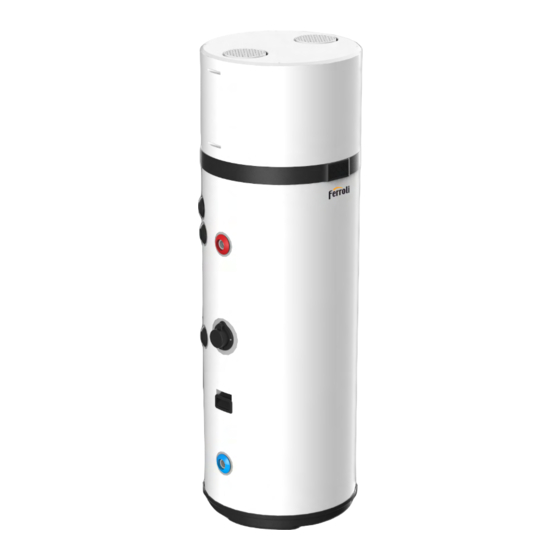
EGEA TECH 200 HT - 260 HT CARATTERISTICHE COSTRUTTIVE fig. 42 Legenda Pompa di calore Interfaccia utente Involucro di acciaio Resistenza elettrica Anodo di magnesio Ingresso aria di ventilazione Ø 160mm Uscita aria di ventilazione Ø 160mm Collegamento di entrata dell’acqua fredda Ø 1”G Collegamento di uscita dell’acqua calda Ø... -
Seite 40: Dati Dimensionali
EGEA TECH 200 HT - 260 HT DATI DIMENSIONALI fig. 44 Legenda a pagina precedente. fig. 46 Ø Legenda a pagina precedente. MODELLO 200 HT 260 HT 1162 1142 1427 1607 1892 1261 fig. 45 Legenda a pagina precedente. cod. 3540000420 - Rev. 03 - 09/2023... -
Seite 41: Caratteristiche Tecniche
EGEA TECH 200 HT - 260 HT CARATTERISTICHE TECNICHE Modello 200 HT 260 HT U.m. Tensione di alimentazione 230Vac-50Hz Contenuto di acqua accumulo - Vnom Pressione massima acqua in ingresso Peso a vuoto Peso in funzionamento Dati generali Dimensioni (fxh) 621 x 1607 621 x 1892 Max. -
Seite 42: Installazione E Messa In Servizio
EGEA TECH 200 HT - 260 HT INSTALLAZIONE E MESSA IN SERVIZIO LIMITI DI IMPIEGO L’installazione, la messa in servizio e la manutenzione del Questo prodotto non è stato pro prodotto devono essere eseguite da personale qualifi- gettato, né è da intendersi come cato e autorizzato. -
Seite 43: Condizioni Ambientali Per Il Funzionamento
EGEA TECH 200 HT - 260 HT 8.3.1 Condizioni ambientali per il funzionamento NB: Nella fase di progettazione e costruzione degli impianti, devo L’apparecchiatura non può ope rare in locali classificati come no essere rispettati i regolamenti OBBLIGO e le disposizioni locali applicabi ambienti con atmosfera esplosi... -
Seite 44: Fissaggio A Pavimento
EGEA TECH 200 HT - 260 HT FISSAGGIO A PAVIMENTO Per fissare il prodotto al pavimento, applicare le staffe fornite come mostrato nella fig. 49. 300 mm 600 mm 600 mm fig. 49 Fissaggio delle staffe Quindi, assicurare l’unità al pavimento con l’aiuto di tasselli fig. -
Seite 45: Collegamenti Aeraulici
EGEA TECH 200 HT - 260 HT COLLEGAMENTI AERAULICI Eseguire l’installazione di ogni canale d’aria facendo attenzio- ne che questo: In molte immagini di questo do • Non gravi con il suo peso sull’apparecchiatura stessa. cumento la posizione dei canali •... -
Seite 46: Collegamenti Aeraulici Sistema In Cascata
EGEA TECH 200 HT - 260 HT La depressione può provocare il reflusso dei gas 8.6.3 Installazione speciale di scarico nell’ambiente. Una delle peculiarità dei sistemi di riscaldamento a pompa di calore è che • Non mettere in funzione la pompa di calore in queste unità... -
Seite 47: Collegamenti Aeraulici Vietati
EGEA TECH 200 HT - 260 HT COLLEGAMENTI IDRAULICI Entrata aria obbligatoria D.160 mm Collegare la linea di alimentazione dell’acqua e la linea di usci- ta ai punti di collegamento appropriati (fig. 56). La tabella sotto riporta le caratteristiche dei punti di collegamento. Serrandina "A"... -
Seite 48: Collegamenti Idraulici Standard
EGEA TECH 200 HT - 260 HT • L’acqua può gocciolare dal tubo di scarico del disposi tivo di sovrappressione; la ATTENZIONE sciare questo tubo aperto all’atmosfera. • Il dispositivo di decompres sione deve essere azionato regolarmente per rimuovere i depositi di calcare e per ve >3°... -
Seite 49: Collegamenti Idraulici Sistema In Cascata
EGEA TECH 200 HT - 260 HT 8.7.2 Collegamenti idraulici sistema in cascata Le figure seguenti (fig. 60 - fig. 61 - fig. 62) illustrano 3 esempi di collegamento idraulico. 8.7.2.1 Esempio impianto idrico SENZA valvola miscelatrice termostatica 16 17 11 10 12 10 17 fig. - Seite 50 EGEA TECH 200 HT - 260 HT 8.7.2.2 Esempio impianto idrico CON valvola miscelatrice termostatica (ricircolo su connessione ingresso acqua fredda unità) 16 17 11 10 12 10 17 fig. 61 Esempio impianto idrico CON valvola miscelatrice termostatica (ricircolo su connessione ingresso acqua fredda unità) Legenda Tubo di entrata Vaso di espansione...
- Seite 51 EGEA TECH 200 HT - 260 HT 8.7.2.3 Esempio impianto idrico CON valvola miscelatrice termostatica (ricircolo su connessione ricircolo acqua unità) 11 10 12 10 17 SLAVE SLAVE MASTER fig. 62 Esempio impianto idrico CON valvola miscelatrice termostatica (ricircolo su connessione ricircolo acqua unità) Legenda Tubo di entrata Regolatore di pressione...
-
Seite 52: Collegamento Dello Scarico Condensa
EGEA TECH 200 HT - 260 HT COLLEGAMENTI ELETTRICI 8.7.3 Collegamento dello scarico condensa La condensa che si forma durante il funzionamento della pompa L’apparecchiatura è dotata di cavo di alimentazione con spina di calore scorre attraverso uno speciale tubo di scarico (1/2”G) Schuko per essere collegata alla rete elettrica tramite idonea che passa all’interno dell’involucro isolante ed esce sul fianco presa (fig. -
Seite 53: Collegamenti Remoti
EGEA TECH 200 HT - 260 HT 8.8.1 Collegamenti remoti Modalità di connessione remota Per il collegamento agli ingressi digitali, l’apparecchiatura è NOTA: per un sistema in CASCATA i collegamenti remoti vanno dotata di un cavo a 6 conduttori supplementare (DIG1=cavo eseguiti solo sul MASTER. -
Seite 54: Schema Elettrico
EGEA TECH 200 HT - 260 HT SCHEMA ELETTRICO EMC filter Power supply CN18 230 V~ 50Hz YE-GN CN16 CN20 CN15 CN13 CN11-1 CN11-2 CN26 CN10 YE-GN CN14-1 YE-GN FUSE YE-GN T5AL250V CN14-2 YE-GN CN19 CN17 AC FAN YE-GN YE-GN CN12 CN25 PE-PR... -
Seite 55: Schema Elettrico Cascata
EGEA TECH 200 HT - 260 HT 8.10 SCHEMA ELETTRICO CASCATA HGBP EMC filter E’ possibile collegare sino a 8 unità in cascata. Per realizzare la cascata è necessario n°1 “kit interfaccia seriale TTL-RS485” per ciascuna unità. Power supply CN18 230 V~ 50Hz YE-GN CN16... -
Seite 56: Messa In Servizio
Pertanto eventuali ATTENZIONE interventi richiesti dal cliente ad un Centro Verificare che l’apparecchiatura assistenza tecnica autorizzato FERROLI nel sia libera da attrezzi o utensili di periodo di garanzia convenzionale per pro vario genere. Se presenti, rimuo... -
Seite 57: Sostituzione Fusibile Scheda Di Potenza
EGEA TECH 200 HT - 260 HT • Rimuovere gli eventuali condotti dell’aria. Effettuare lavori di riparazio • Rimuovere il coperchio superiore svitando innanzitutto le viti ne su parti con funzione di di bloccaggio (fig. 72). sicurezza compromette il si ATTENZIONE •... -
Seite 58: Verifica/Sostituzione Anodo Sacrificale
EGEA TECH 200 HT - 260 HT Nel caso in cui l’operatore non sia riuscito a porre rimedio all’a nomalia, spegnere l’apparecchio ATTENZIONE e contattare il Servizio assisten za tecnica comunicando il mo dello del prodotto acquistato. VERIFICA/SOSTITUZIONE ANODO SACRIFI CALE L’integrità... -
Seite 59: Requisiti Per Il Funzionamento, Il Servizio E L'installazione
EGEA TECH 200 HT - 260 HT Condizioni di installazione nel Paese di utilizzo del prodotto. Sostituire il cavo di alimentazione danneggiato con uno nuovo di Verificare che: caratteristiche uguali o equivalenti al cavo originale. • Le dimensioni del vano di installazione siano quelle indicate nel presente manuale. -
Seite 60: Smaltimento
EGEA TECH 200 HT - 260 HT 11. SMALTIMENTO tati di connessioni leak-free. Le bombole di recupero devono essere idonee all’uso e dotate Qualsiasi intervento sull’appa di valvola di sicurezza e valvola di intercettazione, se possibile recchiatura, incluso lo smalti prima di eseguire l’operazione di recupero raffreddare le bom- mento, deve essere eseguito bole. -
Seite 61: Scheda Prodotto
EGEA TECH 200 HT - 260 HT 12. SCHEDA PRODOTTO DESCRIZIONE u.m. 200 HT 260 HT Profilo di carico dichiarato Impostazioni della temperatura del termostato dello scaldabagno °C Classe di efficienza energetica del riscaldamento dell'acqua Efficienza energetica riscaldamento acqua - h Consumo annuo di elettricità... -
Seite 62: Note Sui Dispositivi Radio E App
EGEA TECH 200 HT - 260 HT 13. NOTE SUI DISPOSITIVI RADIO E APP Questo prodotto incorpora un modulo radio (Wi-Fi) ed è confor- me alla direttiva RED (Radio Equipment Directive) 2014/53/EU. Di seguito sono indicati i principali dati della parte radio: •... -
Seite 63: Certificato Di Garanzia
Modalità per far valere la presente Garanzia In caso di guasto, il cliente deve richiedere entro il termine di decadenza di 30 giorni l’intervento del Centro di Assistenza di zona, autorizzato Ferroli S.p.A.. I nominativi dei Centri di Assistenza autorizzati Ferroli S.p.A. sono reperibili: •... - Seite 64 EGEA TECH 200 HT - 260 HT ETICHETTA IMBALLI ITALIA ETICHETTATURA AMBIENTALE IMBALLAGGI ITALIA TURA AMBIENTALE Ai sensi del decreto legislativo 3 settembre 2020, n. 116 e della decisione 97/129/CE , il materiale che compone l’imballaggio dell’ap- parecchio, và gestito nel modo corretto, al fine di facilitarne la raccolta, il riutilizzo, il recupero ed il riciclaggio ove questo sia possibile. Per la corretta gestione della raccolta dell’imballaggio, il consumatore finale deve seguire la tabella riportata nella quale ci sono tutte le indicazioni necessarie.
- Seite 65 EGEA TECH 200 HT - 260 HT NOTE cod. 3540000420 - Rev. 03 - 09/2023...
- Seite 66 EGEA TECH 200 HT - 260 HT SUMARIO ADVERTENCIAS DE SEGURIDAD ..............68 EMBALAJE .................... 99 GLOSARIO DE LA TERMINOLOGÍA ..........100 GENERALIDADES ..................... 74 DISPOSITIVOS DE PROTECCIÓN INDIVIDUAL ....... 100 DESTINATARIOS DEL MANUAL ............74 RUIDO ....................100 GUÍA DEL MANUAL ................75 VIBRACIONES ..................
-
Seite 67: Datos Del Fabricante
En caso de pérdida o deterioro de este manual, puede des- Para el centro de asistencia consultar: cargarse una copia adicional desde el sitio www.ferroli.com www.ferroli.com seleccionando el producto comprado. Las imágenes son meramente indicativas y no constituyen un IDENTIFICACIÓN DEL APARATO... -
Seite 68: Advertencias De Seguridad
ATENCIÓN gentes a nivel local. to comprado. El equipo debe ser instalado y puesto en servicio por un técni... - Seite 69 EGEA TECH 200 HT - 260 HT • El agua puede gotear de la Este producto está diseñado manguera de drenaje de la para ser utilizado a una altitud válvula de seguridad; dejar máxima de 2000 m. ATTENZIONE ATENCIÓN este tubo abierto a la atmósfe •...
- Seite 70 EGEA TECH 200 HT - 260 HT Para el correcto funcionamiento del aparato, es imprescindible No utilizar alargadores ni adapta instalar una válvula de seguridad ATENCIÓN dores. de 0,7 MPa (7 bar, no suministra ATENCIÓN da) en la entrada de agua fría. Este dispositivo de seguridad no Para la conexión a la red y los debe ser manipulado y debe ser...
- Seite 71 EGEA TECH 200 HT - 260 HT En caso de sustitución del fusi ble sustituirlo con uno nuevo de 5 A 250V de tipo retardado certi ficado IEC 601272/II (T5AL250V) ATENCIÓN (consultar el apar. 9.1 en la pági na 121). Antes de cualquier intervención de reparación del producto leer atentamente el esquema eléctri...
-
Seite 72: Uso Incorrecto Razonablemente Previsible
Fabricante. En ausencia de dicha autorización escrita, el empleo se con- sidera “uso inadecuado”; por lo tanto FERROLI declina toda responsabilidad por los daños causados a los bienes o a las personas y considera nula toda garantía sobre el suministro. - Seite 73 EGEA TECH 200 HT - 260 HT ► PELIGRO DE MUERTE A CAUSA DE El refrigerante no debe ser liberado a la atmósfera. LAS MODIFICACIONES AL PRODUC- Antes de desechar el equipo, el refrigerante que contiene debe TO O AL AMBIENTE DE INSTALACIÓN recuperarse en un contenedor adecuado para ser reciclado o eliminado de acuerdo con la normativa vigente.
-
Seite 74: Generalidades
EGEA TECH 200 HT - 260 HT DESTINATARIOS DEL MANUAL INSTRUCCIONES PARA: El manual está dirigido al instalador especializado (instalado- res – técnicos de mantenimiento) y al usuario final. Para distinguir el contenido del manual en base a las caracte- TÉCNICO EXPERTO / ASISTENCIA USUARIO rísticas del destinatario (usuario y técnico experto), las instruc-... -
Seite 75: Guía Del Manual
Para el uso correcto del aparato la referencia técnica es el está disponible en la versión digital descargable desde el sitio “MANUAL DE USO, INSTALACIÓN Y MANTENIMIENTO” www.ferroli.com seleccionando el producto comprado. suministrado con el mismo. El manual debe conservarse para posibles consultas durante Para que el manual de instrucciones sea conforme con los toda la vida útil del aparato. -
Seite 76: Conformidad Con Los Reglamentos Europeos
EGEA TECH 200 HT - 260 HT CONFORMIDAD CON LOS REGLAMENTOS EXCLUSIÓN DE RESPONSABILIDAD EUROPEOS La correspondencia del contenido de estas instrucciones de uso con el hardware y el software ha sido sometida a una ve- Esta bomba de calor es un aparato destinado al uso doméstico rificación precisa. -
Seite 77: Limpieza General Y Del Panel De Control
EGEA TECH 200 HT - 260 HT No desconectar el enchufe de la CONTROL DEL APARATO toma de corriente halando el ca ble de alimentación. Frecuencia: PELIGRO ANUAL 3.2.1 Limpieza general y del panel de control TÉCNICO EXPERTO / USUARIO ASISTENCIA TÉCNICA Frecuencia: Equipo a utilizar... -
Seite 78: Descripción De La Interfaz De Usuario
EGEA TECH 200 HT - 260 HT DESCRIPCIÓN DE LA INTERFAZ DE USUARIO La interfaz de usuario de este modelo de calentador de agua consta de cuatro teclas capacitivas y una pantalla LED. Tan pronto como se enciende el calentador de agua, las cuatro teclas y todos los íconos en la pantalla se iluminan, luego se muestra la versión del firmware de la pantalla. -
Seite 79: Apagado (Standby Off)
EGEA TECH 200 HT - 260 HT 3.5.2 Apagado (Standby Off) La bomba de calor se enciende 5 minutos después selección de este modo o desde el último apagado. Con el calentador de agua encendido y la función “bloqueo de teclas” En caso de apagado, dentro de los primeros 5 minu- activa, primero es necesario “desbloquear”... -
Seite 80: Funcionalidad En Cascada
EGEA TECH 200 HT - 260 HT FUNCIONALIDAD EN CASCADA CÓMO ACCEDER AL MENÚ DE USUARIO E INSTALADOR El término cascada pretende indicar un grupo de calentadores de agua que trabajan en conjunto, dentro de los cuales se iden- Además de la posibilidad de cambiar el set-point, desde el display tifica solo un MASTER y varios SLAVEs. -
Seite 81: Uso De Las Teclas Durante La Navegación Por Los Menús
EGEA TECH 200 HT - 260 HT 3.9.1 Uso de las teclas durante la navegación por los menús Posteriormente puede elegir los días en los que configurar la programación según los valores de la tabla: Acción Símbolo Dentro de un menú o submenú Al editar un parámetro Valor Descripción... -
Seite 82: Menú Fan - Ajuste Ventilador Y Modo Silencioso
EGEA TECH 200 HT - 260 HT confirmar (un pitido confirmará la modificación) o la tecla “ON/ 3.9.5 MONITOREO DE ENERGÍA OFF” para salir del menú. Para visualizar el consumo eléctrico, la energía térmica pro- ducida y la energía renovable, acceda al menú Es pulsando Realice el mismo procedimiento para las franjas ho- la tecla “SET”... -
Seite 83: Menú Rst - Reset
EGEA TECH 200 HT - 260 HT Ejemplo de lectura NOTA: * : para la lectura correcta de este parámetro, el valor re La función Energy Monitoring permite, sultante de las 3 pantallas debe dividirse por 10. a través de algoritmos propietarios, una estimación de los valores de energía tér... -
Seite 84: Menú Hi - Configuración Del Calentador Eléctrico
EGEA TECH 200 HT - 260 HT 3.9.8 Menú HI - Configuración del calentador eléctrico Para configurar los parámetros, acceda al menú phv, presio- nando la tecla “SET” aparecerá el valor “P01”. Unidad Paráme- Descripción de medi- defec- máximo Nivel Unidad Paráme- máxi-... -
Seite 85: Menú Sg Funcionalidad Smart Grid (Ver También "8.8.1 Conexiones Remotas")
EGEA TECH 200 HT - 260 HT a 20°C y el setpoint = 50°C el setpoint será 50+20=70°C. Con la función fotovoltaica activa (P01 puesto a 1), la bomba En cualquier caso, por defecto la consigna máxima es de calor y la resistencia eléctrica se activarán simultáneamen- 75°C, por lo tanto si offset=30°C y consigna=50°C la con- te hasta alcanzar la consigna establecida para este modo. -
Seite 86: Menú Rec - Configuración Bomba De Recirculación
EGEA TECH 200 HT - 260 HT 3.9.12 Menú rEC - Configuración BOMBA DE RECIRCULACIÓN Unidad Valor Descripción de medi- defec- máximo Nivel Unidad Valor Descripción de medi- defec- máximo Nivel Habilitación de la función solar térmica (0=deshabilitado, 1=habilitado) Habilitación de la bomba de circulación Temperatura máxima de funcionamiento °C (0=deshabilitado, 1=habilitado) -
Seite 87: Menú Cas - Cascata
EGEA TECH 200 HT - 260 HT por el parámetro h04. Unidad de máxi- Valor Descripción Nivel medi-da defec-to Unidad de máxi- Valor Descripción Nivel Número de unidades encendidas con medi-da defec-to máx. h01 Activación de la función antilegionela Tiempo de rotación de prioridad h02 Consigna ciclo antilegionela °C Compensación para restablecer el tiempo... -
Seite 88: Menú Uts - Visualización De Marca, Gama, Modelo, Número De Serie
EGEA TECH 200 HT - 260 HT c08: El parámetro define el tiempo de rotación expresado en días para definir el período de rotación cíclica de funciona- miento de las distintas unidades. La rotación cíclica tiene como objetivo garantizar un uso y por lo tanto un desgaste equili- fig. -
Seite 89: Control Del Equipo Mediante La Aplicación
12 Registro de usuario Para utilizar la aplicación "Ferroli Home" por primera vez, es 3. Política de Privacidad necesario registrarse como usuario: crear una nueva cuenta → introducir el número de teléfono móvil/dirección de correo electrónico →... - Seite 90 EGEA TECH 200 HT - 260 HT 4. Términos y condiciones de uso 6. PIN fig. 14 fig. 16 5. Contraseñas 7. Registro completado fig. 15 fig. 17 cod. 3540000420 - Rev. 03 - 09/2023...
- Seite 91 EGEA TECH 200 HT - 260 HT 8. Página de inicio en blanco. 10. Permiso de cámara. fig. 18 fig. 20 9. Método de asociación 11. Matriz de datos fig. 19 fig. 21 cod. 3540000420 - Rev. 03 - 09/2023...
- Seite 92 EGEA TECH 200 HT - 260 HT 12. Tipo y modelo de dispositivo. 14. Activación Bluetooth y generación de PIN de autentica- ción. fig. 22 fig. 24 15. Búsqueda de Bluetooth. 13. Permiso de bluetooth para teléfonos inteligentes fig. 25 fig.
- Seite 93 EGEA TECH 200 HT - 260 HT 16. Dispositivos Bluetooth cercanos 18. Conexión a la red wifi fig. 26 fig. 28 Seleccione el dispositivo cuyo nombre comience con BT-1955 19. Información de Wi-Fi. 17. PIN de 3 dígitos fig. 29 fig.
- Seite 94 EGEA TECH 200 HT - 260 HT 20. Datos incorrectos WI-FI. 22. Conexión. fig. 30 fig. 32 21. Conexión 23. Apodos fig. 31 fig. 33 cod. 3540000420 - Rev. 03 - 09/2023...
- Seite 95 EGEA TECH 200 HT - 260 HT 24. Fin de la asociación. 26. Página de inicio fig. 36 fig. 34 27.Ingreso de credenciales 25. Cascada fig. 37 fig. 35 cod. 3540000420 - Rev. 03 - 09/2023...
-
Seite 96: Fallos/Protección
EGEA TECH 200 HT - 260 HT 3.12 FALLOS/PROTECCIÓN En caso de que se presen Este aparato dispone de un sistema de autodiagnóstico que ten uno o varios de los fa analiza algunos fallos y protecciones contra anomalías de fun- llos mencionados arriba, es cionamiento mediante: detección, aviso y adopción de un pro- necesario contactar a asis... -
Seite 97: Localización De Fallos
EGEA TECH 200 HT - 260 HT 3.13 LOCALIZACIÓN DE FALLOS Si el aparato no funciona correctamente, aunque no haya se- ñales de alarma, antes de contactar con la asistencia técnica del fabricante, se recomienda seguir estas indicaciones. Anomalía Acción recomendada •... -
Seite 98: Informaciones Generales
EGEA TECH 200 HT - 260 HT INFORMACIONES GENERALES INSTRUCCIONES PARA: DATOS DE LA PLACA Consultar la placa de datos colocada en el aparato y verificar que el manual de uso corresponda con el modelo indicado. TÉCNICO EXPERTO / ASISTENCIA USUARIO TÉCNICA DEL FABRICANTE D.P.I. -
Seite 99: Placas De Identificación De Los Principales Elementos
EGEA TECH 200 HT - 260 HT Símbolo Definición No alterar de ningún modo la pla ca de datos. PROHIBICIÓN GENÉRICA. ATENCIÓN Símbolo utilizado para identificar la prohibi- ción de la descripción prescrita. PROHIBICIÓN En el caso de solicitud de informaciones o de asistencia téc- nica, es necesario especificar, además del modelo y el tipo de PESO. -
Seite 100: Glosario De La Terminología
EGEA TECH 200 HT - 260 HT DISPOSITIVOS DE PROTECCIÓN INDIVIDUAL Símbolo Definición La indumentaria de quien opera o realiza el mantenimiento Indica la posición en el bulto de transporte debe estar conforme con los requisitos esenciales de seguri- donde deben colocarse los terminales dad definidos por las leyes vigentes en el país donde el mismo durante el desplazamiento con medios es instalado. -
Seite 101: Riesgos Residuales
EGEA TECH 200 HT - 260 HT RIESGOS RESIDUALES Durante las fases de manipula El diseño ha sido realizado de modo de garantizar los requi- ción e instalación del producto, sitos esenciales de seguridad para el operador encargado y la parte superior no debe sufrir ATTENZIONE para el usuario final. -
Seite 102: Desplazamiento Del Embalaje
EGEA TECH 200 HT - 260 HT DESPLAZAMIENTO DEL EMBALAJE trada digital hexapolar 3x soportes de fijación y tornillos correspondientes El aparato se suministra en una caja de cartón sobre un palé • 1x termostato de seguridad (solo para 200 LT-S e de madera. -
Seite 103: Características Constructivas
EGEA TECH 200 HT - 260 HT CARACTERÍSTICAS CONSTRUCTIVAS Leyenda fig. 42 bomba de calor Interfaz de usuario carcasa de acero Resistencia eléctrica Ánodo de magnesio Entrada de aire de ventilación Ø 160mm Salida de aire de ventilación Ø 160mm Conexión entrada agua fría Ø... -
Seite 104: Datos Dimensionales
EGEA TECH 200 HT - 260 HT DATOS DIMENSIONALES fig. 44 Legenda a pagina precedente. fig. 46 Ø Legenda a pagina precedente. MODELLO 200 HT 260 HT 1162 1142 1427 1607 1892 1261 fig. 45 Legenda a pagina precedente. cod. 3540000420 - Rev. 03 - 09/2023... -
Seite 105: Características Técnicas
EGEA TECH 200 HT - 260 HT CARACTERÍSTICAS TÉCNICAS Modelos 200 HT 260 HT U.m. Suministro de voltaje 230Vac-50Hz Contenido de agua del tanque - Vnom Presión máxima de agua de entrada Peso vacio Peso operativo Informacion General Dimensiones (fxh) 621 x 1607 621 x 1892 Max. -
Seite 106: Instalación Y Puesta En Marcha
EGEA TECH 200 HT - 260 HT INSTALACIÓN Y PUESTA EN LÍMITES DE EMPLEO MARCHA Este producto no ha sido diseña La instalación, la puesta en marcha y el mantenimiento del do, ni está previsto como tal, para aparato deben ser efectuados por personal cualificado ATENCIÓN su uso en ambientes peligrosos y autorizado. -
Seite 107: Condiciones Ambientales Para El Funcionamiento
EGEA TECH 200 HT - 260 HT 8.3.1 Condiciones ambientales para el funcionamiento Nota: En la fase de diseño y con strucción de las plantas, se de El aparato no puede operar en locales clasificados como am ben cumplir las disposiciones y OBLIGACIÓN disposiciones locales aplicables. -
Seite 108: Fijación De Suelo
EGEA TECH 200 HT - 260 HT FIJACIÓN DE SUELO Para fijar el producto al suelo, aplique los soportes suministra- dos como se muestra en fig. 49. 300 mm 600 mm 600 mm fig. 49 Fijación de los soportes Luego, fije la unidad al piso con la ayuda de anclajes adecua- fig. -
Seite 109: Conexiones Aeráulicas
EGEA TECH 200 HT - 260 HT CONEXIONES AERÁULICAS Instalar cada canal de aire prestando atención a que: • No fuerce el aparato con su peso. En muchas imágenes de este do • Permita hacer las operaciones de mantenimiento. cumento se esquematiza la po •... -
Seite 110: Conexiones Aeráulicas Sistema Cascada
EGEA TECH 200 HT - 260 HT 8.6.3 Instalación especial La depresión puede provocar el retorno de los Una de las peculiaridades de los sistemas de calefacción de la gases de combustión al ambiente. bomba de calor es que estas unidades reducen considerable- •... -
Seite 111: Conexiones Aeráulicas Prohibidas
EGEA TECH 200 HT - 260 HT CONEXIONES HIDRÁULICAS Entrada de aire obligatoria D.160 mm Conecte la línea de suministro de agua fría y la línea de salida a los puntos de conexión apropiados (fig. 56). La siguiente tabla muestra las características de los puntos de Compuerta "A"... -
Seite 112: Conexiones Hidráulicas Estándar
EGEA TECH 200 HT - 260 HT • El agua puede gotear del tubo de drenaje del dispositivo de alivio de presión; dejar este ATENCIÓN tubo abierto a la atmósfera. • El dispositivo de descom presión debe accionarse re gularmente para remover los >3°... -
Seite 113: Conexiones De Fontanería Del Sistema En Cascada
EGEA TECH 200 HT - 260 HT 8.7.2 Conexiones de fontanería del sistema en cascada Las siguientes figuras (fig. 60 - fig. 61 - fig. 62) muestran 2 ejemplos de conexión hidráulica 8.7.2.1 Ejemplo de sistema de agua SIN válvula mezcladora termostática 16 17 11 10 12 10 17... - Seite 114 EGEA TECH 200 HT - 260 HT 8.7.2.2 Ejemplo de sistema de agua CON válvula mezcladora termostática (recirculación en la conexión de entrada de agua fría de la unidad) 16 17 11 10 12 10 17 SLAVE SLAVE MASTER fig. 61 Ejemplo de sistema de agua CON válvula mezcladora termostática (recirculación en la conexión de entrada de agua fría de la unidad) Legenda tubo de entrada...
- Seite 115 EGEA TECH 200 HT - 260 HT 8.7.2.3 Ejemplo de sistema de agua CON válvula mezcladora termostática (recirculación en conexión de recirculación de agua de la unidad) 11 10 12 10 17 SLAVE SLAVE MASTER fig. 62 Ejemplo de sistema de agua CON válvula mezcladora termostática (recir- culación en conexión de recirculación de agua de la unidad) Legenda tubo de entrada...
-
Seite 116: Conexión Del Drenaje De Condensado
EGEA TECH 200 HT - 260 HT CONEXIONES ELÉCTRICAS 8.7.3 Conexión del drenaje de condensado Conexión de drenaje de condensación El aparato está dotado de cable de alimentación con enchufe La condensación que se forma durante el funcionamiento de la Schuko para ser conectado a la red eléctrica mediante toma bomba de calor fluye a través de un tubo de drenaje especial adecuada (fig. -
Seite 117: Conexiones Remotas
EGEA TECH 200 HT - 260 HT 8.8.1 Conexiones remotas Modo de conexión remota Para la conexión a las entradas digitales, el equipo está equipa- NOTA: para un sistema CASCADA, las conexiones remotas de do con un cable adicional de 6 conductores (DIG1=EVU/SG0= ben realizarse solo en el MASTER. -
Seite 118: Esquema Eléctrico
EGEA TECH 200 HT - 260 HT ESQUEMA ELÉCTRICO EMC filter Power supply CN18 230 V~ 50Hz YE-GN CN16 CN20 CN15 CN13 CN11-1 CN11-2 CN26 CN10 YE-GN CN14-1 YE-GN FUSE YE-GN T5AL250V CN14-2 YE-GN CN19 CN17 AC FAN YE-GN YE-GN CN12 CN25 PE-PR... -
Seite 119: Diagrama De Cableado En Cascada
EGEA TECH 200 HT - 260 HT 8.10 DIAGRAMA DE CABLEADO EN CASCADA HGBP EMC filter Es posible conectar hasta 8 unidades en cascada. Para crear la cascada, se requiere n°1 “kit de interfaz serie TTL-RS485” para cada unidad. Power supply CN18 230 V~ 50Hz YE-GN... -
Seite 120: Puesta En Marcha
Las intervenciones solicitadas por el Verificar que el aparato esté libre cliente a un Centro de asistencia técnica au de herramientas o utensilios de torizado FERROLI durante el período de ga distinto género. Si los hay, reti CONTROL rantía convencional por problemas debidos a VISUAL rarlos. -
Seite 121: Sustitución Fusible Tarjeta De Potencia
EGEA TECH 200 HT - 260 HT RESTABLECIMIENTO TERMOSTATO DE Antes de emprender cualquier SEGURIDAD DE LA RESISTENCIA ELÉCTRICA trabajo de mantenimiento ase gurarse de que el aparato no Este equipo cuenta con un termostato de seguridad con resta- ATENCIÓN esté... -
Seite 122: Control/Sustitución Ánodo Sacrificial
EGEA TECH 200 HT - 260 HT El disparo del termostato de se guridad puede obedecer a un fa llo ligado a la tarjeta de control o ATENCIÓN a la ausencia de agua en el depó sito. NOTA: El disparo del termostato excluye el funcionamiento de la resistencia eléctrica pero no el sistema con bomba de calor dentro de los límites de funcionamiento permitidos. -
Seite 123: Requisitos Para El Funcionamiento, El Servicio Y La Instalación
EGEA TECH 200 HT - 260 HT 10. REQUISITOS PARA EL formes a lo indicado en este manual. • Haya una ventilación adecuada del local. FUNCIONAMIENTO, EL SERVICIO Y LA • Las marcas y los signos gráficos aplicados al aparato estén INSTALACIÓN presentes y sean legibles. -
Seite 124: Información Para Los Usuarios
EGEA TECH 200 HT - 260 HT contar con conexiones leak-free. Cualquier intervención en el apa Las bombonas de recuperación deben ser adecuadas para el rato, incluida la eliminación, debe uso y estar equipadas con una válvula de seguridad y una vál- ser realizada por personal cali... -
Seite 125: Ficha Del Aparato
EGEA TECH 200 HT - 260 HT 12. FICHA DEL APARATO Descripciones u.m. 200 HT 260 HT Perfil de carga declarado Ajustes de temperatura del termostato del calentador de agua °C Clase de eficiencia energética de calentamiento de agua Eficiencia energética de calentamiento de agua - h Consumo eléctrico anual - AEC 1315 Nivel de potencia acústica interior... -
Seite 126: Notas Sobre Los Dispositivos Yapp
EGEA TECH 200 HT - 260 HT 13. NOTAS SOBRE LOS DISPOSITIVOS Y Este producto incorpora un módulo radio (Wi-Fi) y cumple con la directiva RED (Radio Equipment Directive) 2014/53/EU. A conti- nuación se muestran los principales datos de la parte de radio: •... -
Seite 127: Certificado De Garantía
• instrucciones técnicas suministradas con los equipos. Sera necesario presentar al personal técnico de FERROLI, antes de su intervención, la factura o ticket de • compra del aparato, junto al albarán de entrega correspondiente, si este fuese de fecha posterior. - Seite 128 EGEA TECH 200 HT - 260 HT SUMMARY SAFETY WARNINGS .................130 DESCRIPTION OF THE SYMBOLS USED IN THE MANUAL AND ON THE PACKAGING ................161 GENERAL INFORMATION ................136 GLOSSARY OF TERMS..............162 RECIPIENTS OF THE MANUAL ............136 PERSONAL PROTECTIVE EQUIPMENT ........162 GUIDE TO THE MANUAL ..............137 NOISE.....................162 VIBRATIONS ..................162 2.2.1...
-
Seite 129: Manufacturer´s Data
For any request for TECHNICAL ASSISTANCE on the ma- user/owner. chine, refer to the following contacts. In the event of loss of or damage to this manual, another copy can be downloaded from the website www.ferroli.com by se- For the service centre, visit: lecting the purchased product. www.ferroli.com The images are for illustrative purpose only and do not consti- tute a commitment for the manufacturer and/or the Distributor. -
Seite 130: Safety Warnings
ATTENTION complied with. chased product. The equipment must be installed and operated by a qualified tech... - Seite 131 EGEA TECH 200 HT - 260 HT For models including a heat • Water may drip from the safe exchanger (solar coil), the circu ty valve drain hose; leave this it must not exceed 1.0 MPa (10 tube open to the atmosphere. ATTENZIONE ATTENTION bar) and its temperature must...
- Seite 132 EGEA TECH 200 HT - 260 HT Use only connecting pipes (not The device must be protected by supplied), rigid and resistant to an adequate differential switch. electrolysis both at the inlet of The type of differential switch ATTENTION ATTENTION cold water and at the outlet of hot should be selected by assess...
-
Seite 133: Reasonably Foreseeable Misuse
Manufacturer. In the absence of such written authorisation, the use is to be considered “improper use”; therefore FERROLI declines all responsibility in relation to any damage caused to things or people and deems any type of guarantee on supply null and void. - Seite 134 EGEA TECH 200 HT - 260 HT ► INTENDED USE OF THE DEVICE ► DANGER OF DEATH DUE TO CHANGES TO THE PRODUCT OR The device is intended to be used in a domestic environment THE INSTALLATION ENVIRONMENT within the limits of allowed environmental conditions indicated •...
-
Seite 135: Dangers From Changes In The Installation Room
EGEA TECH 200 HT - 260 HT Any intervention on the ap pliance, including disposal, must be carried out by quali fied personnel with a suitable refrigeration technician’s li cense aimed at understanding EXPERT TECHNICIAN and managing systems contai ning HFC type gases. ►... -
Seite 136: General Information
EGEA TECH 200 HT - 260 HT RECIPIENTS OF THE MANUAL INSTRUCTIONS FOR: It is intended for the specialist installer (installers - mainte- nance technicians) and the end user. To distinguish the content of the manual based on the char- EXPERT TECHNICIAN / acteristics of the recipient (user and expert technician), the in- USER... -
Seite 137: Guide To The Manual
For the correct use of the device, the technical reference is in digital version, which can be downloaded from the website the “USE, INSTALLATION AND MAINTENANCE MANUAL” www.ferroli.com by selecting the purchased product. supplied with it. The manual must be kept for future reference until dismantling. -
Seite 138: Compliance With European Regulations
EGEA TECH 200 HT - 260 HT COMPLIANCE WITH EUROPEAN DISCLAIMER OF LIABILITY REGULATIONS The conformity of these operating instructions with the hard- ware and the software has been carefully checked. There may, This heat pump is a product intended for domestic use in com- however, be some differences, therefore, we do not assume pliance with the following European directives: any liability if they are incomplete. -
Seite 139: General And Control Panel Cleaning
EGEA TECH 200 HT - 260 HT CHECK OF THE DEVICE Do not remove the plug from the Periodicity: socket by pulling the power cord. DANGER YEARLY EXPERT TECHNICIAN 3.2.1 General and control panel cleaning / MANUFACTURER'S USER TECHNICAL Equipment to be ASSISTANCE Periodicity: used... -
Seite 140: Description Of The User Interface
EGEA TECH 200 HT - 260 HT DESCRIPTION OF THE USER INTERFACE The user interface of this model of water heater con- sists of four capacitive keys and an LED display. As soon as the water heater is powered, the four keys and all the icons on the display are backlit, then the display firmware version is shown on the display. -
Seite 141: Standby
EGEA TECH 200 HT - 260 HT the water heater (a long beep will be heard) 3.6.4 VENTILATION FAn ” is shown on the display 3.5.3 Standby With this mode only the fan inside the appliance is used and In standby mode, the wording Stb is shown on the display. it is useful if you want to recirculate the air in the installation In this mode, the heat pump is off, but all the auxiliary functions environment. -
Seite 142: Cascade Functionality
EGEA TECH 200 HT - 260 HT CASCADE FUNCTIONALITY HOW TO ACCESS THE USER AND INSTAL LER MENU The term cascade is intended to indicate a group of water he- aters that work together, within which only one Master and se- addition possibility changing... -
Seite 143: Using The Keys While Navigating In The Menus
EGEA TECH 200 HT - 260 HT 3.9.1 Using the keys while navigating in the menus ming is disabled, default value). To activate time band programming, use the “+” and “-” keys to bring the value to “1”. Action Symbol Within a menu or submenu While editing a parameter Subsequently you can choose the days on which to set the... -
Seite 144: Fan Menu - Fan And Silent Mode Setting
EGEA TECH 200 HT - 260 HT 3.9.5 ENERGY MONITORING Then press the “SET” key for 3 secon- ds to confirm (a beep will confirm the modifica- The Energy Monitoring function al tion) or the “ON/OFF” key to exit the menu. lows, through proprietary algorithms, an estimate of the values of thermal NOTA... -
Seite 145: Rst Menu - Reset
EGEA TECH 200 HT - 260 HT NOTA: Value Description Unit of measure Level * : for the correct reading of this parameter, the va Et3 * Weekly thermal energy kWh / 10 * U / I lue resulting from the 3 screens must be divided by 10. Monthly thermal energy U / I Ex. -
Seite 146: Hi Menu - Electric Heater Setting
EGEA TECH 200 HT - 260 HT 3.9.8 HI menu ELECTRIC HEATER SETTING Parame- Unit of Description default min max Level measure Unit of Value Description default min Level Enable EVU function measure (0=disabled, 1=enabled) Enabling heater in ECO mode when Unit mode with EVU input open protection alarm (0=OFF, 1=Standby) -
Seite 147: Sg Menu - Smart Grid Functionality
EGEA TECH 200 HT - 260 HT setpoint=50°C the photovoltaic setpoint will not be 50+30=80 Unit of Value Description default min Level measure but 75°C. Enable Smart Grid function (0=disabled, 1=enabled) Setpoint offset for operating state 3 °C When the PHOTOVOLTAIC function is enabled, the symbol ap- Level: U=user menu - I=installer menu pears on the display according to the following logic:... -
Seite 148: Rec Menu - Recirculation Pump Setting
EGEA TECH 200 HT - 260 HT L04: represents the duration of the cycle in which the solar night on the fourteenth day. panel circulator remains off L05: if the panel temperature exceeds this value, the SOLAR ATTENTION: the 14-day waiting time cycle may not even be function is deactivated. -
Seite 149: Cas Menu - Cascata
EGEA TECH 200 HT - 260 HT NOTE: value parameter identi- Behavior Description Active mode fies the position of the Slave inside the cascade. ANTI-LEGIONELLA enabled The unit continues to work in the mode on with It is therefore necessary to make sure that the assigned value but not running set by the user steady light... -
Seite 150: More Features
EGEA TECH 200 HT - 260 HT 3.9.15.1 Serial Number display “parameter U03” By accessing the U03 menu you will be able to view the value relating to the serial number. The serial number display is divided into pairs of two characters and is made up of a maximum of 8 pairs. -
Seite 151: Control Of The Device Via App
12 ing the icon as indicated above. User registration To use the"Ferroli Home" application for the first time, user re- 3. Privacy Policy gistration is required: create a new account → enter the mobile phone number/e-mail address → enter the verification code and set the password →... - Seite 152 EGEA TECH 200 HT - 260 HT 4. Terms and conditions of use 6. Pin fig. 14 fig. 16 5. Password 7. Registration completed fig. 15 fig. 17 cod. 3540000420 - Rev. 03 - 09/2023...
- Seite 153 EGEA TECH 200 HT - 260 HT 8. Blank homepage 10. Camera permission. fig. 18 fig. 20 9. Association method 11. Data matrix fig. 19 fig. 21 cod. 3540000420 - Rev. 03 - 09/2023...
- Seite 154 EGEA TECH 200 HT - 260 HT 12. Device type and model. 14. Bluetooth activation and authentication PIN generation. fig. 22 fig. 24 15. Bluetooth search. 13. Smartphone bluetooth permission fig. 25 fig. 23 cod. 3540000420 - Rev. 03 - 09/2023...
- Seite 155 EGEA TECH 200 HT - 260 HT 16. Bluetooth devices nearby 18. Connection to the wifi network fig. 26 fig. 28 Select the device whose name starts with BT-1955 19. Wifi info. 17. 3-digit PIN fig. 29 fig. 27 Enter the PIN shown on the water heater display. cod.
- Seite 156 EGEA TECH 200 HT - 260 HT 20. WI-FI Incorrect data. 22. Connecting. fig. 30 fig. 32 21. Connecting 23. Nickname fig. 31 fig. 33 cod. 3540000420 - Rev. 03 - 09/2023...
- Seite 157 EGEA TECH 200 HT - 260 HT 24. End of association. 26. homepage fig. 34 fig. 36 25. Plant information 27. Login fig. 35 fig. 37 cod. 3540000420 - Rev. 03 - 09/2023...
-
Seite 158: Faults/Protection
EGEA TECH 200 HT - 260 HT 3.12 FAULTS/PROTECTION If one or more of the above This device has a self-diagnosis system that covers some pos- faults occur, contact the sible faults or protections from anomalous operating conditions manufacturer's technical as through: detection, signalling and adoption of an emergency EXPERT TECHNICIAN sistance, indicating the error... -
Seite 159: Troubleshooting
EGEA TECH 200 HT - 260 HT 3.13 TROUBLESHOOTING If the equipment is not working properly, without any alarm sig- naling, before contacting the manufacturer’s technical assis- tance service, it is advisable to carry out the following. Malfunction Recommended action •... -
Seite 160: General Information
EGEA TECH 200 HT - 260 HT GENERAL INFORMATION INSTRUCTIONS FOR: PLATE DATA Read the data plate affixed to the device and check that the user manual corresponds to the model indicated. EXPERT TECHNICIAN / USER MANUFACTURER'S TECHNICAL ASSISTANCE P.P.E. NEEDED: Made in .. -
Seite 161: Identification Plates Of The Main Elements
EGEA TECH 200 HT - 260 HT Symbol Definition Do not tamper with the data plate in any way. GENERIC PROHIBITION. ATTENTION Symbol used to identify the prohibition of the prescribed description. PROHIBITION In the event of a request for information or technical assis- tance, it is necessary to specify, in addition to the model and WEIGHT. -
Seite 162: Glossary Of Terms
EGEA TECH 200 HT - 260 HT PERSONAL PROTECTIVE EQUIPMENT Symbol Definition The clothes worn by people who work or carry out maintenance It indicates the position on the transport work must comply with the essential safety requirements de- package where the clamps must be fined by the laws in force in the country in which it is installed. -
Seite 163: Residual Risks
EGEA TECH 200 HT - 260 HT RESIDUAL RISKS During the handling and instal The design was carried out in order to ensure the essential lation phases of the product, the safety requirements for the operator in charge and for the end upper part must not undergo any ATTENZIONE user. -
Seite 164: Handling Of Packaging
EGEA TECH 200 HT - 260 HT HANDLING OF PACKAGING • 3x fixing brackets and relative screws • 1x safety thermostat (only for 200 LT-S and 260 LT-S mo- The device comes in a cardboard box on a wooden pallet. del). -
Seite 165: Construction Features
EGEA TECH 200 HT - 260 HT CONSTRUCTION FEATURES fig. 42 Legend heat pump User interface Steel casing Electrical heater Magnesium anode Ventilation air inlet Ø 160mm Ventilation air outlet Ø 160mm Cold water inlet connection Ø 1”G Hot water outlet connection Ø 1”G 10 Arrangement for recirculation Ø... -
Seite 166: Dimensional Data
EGEA TECH 200 HT - 260 HT DIMENSIONAL DATA fig. 44 Legend on previous page. fig. 46 Ø Legend on previous page.. MODEL 200 HT 260 HT 1162 1142 1427 1607 1892 1261 fig. 45 Legend on previous page. cod. 3540000420 - Rev. 03 - 09/2023... -
Seite 167: Technical Features
EGEA TECH 200 HT - 260 HT TECHNICAL FEATURES Models 200 HT 260 HT U.m. Voltage supplie 230Vac-50Hz Tank water content - Vnom Maximum inlet water pressure Empty weight General data Operating weight Dimensions (fxh) 621 x 1607 621 x 1892 Max. -
Seite 168: Installation And Commissioning
EGEA TECH 200 HT - 260 HT INSTALLATION AND LIMITS OF USE COMMISSIONING This product has not been de signed, nor is it intended as such, Product installation, commissioning and maintenance to be used in hazardous envi must be carried out by qualified and authorised per- ATTENTION ronments according to Directive sonnel. -
Seite 169: Environmental Conditions For Operation
EGEA TECH 200 HT - 260 HT 8.3.1 Environmental conditions for operation NB: In the design and construc tion phase of the plants, the ap The device cannot operate in rooms classified as environ plicable local regulations and OBLIGATION provisions must be complied ments with an explosive atmos... -
Seite 170: Floor Fixing
EGEA TECH 200 HT - 260 HT FLOOR FIXING To fix the product to the floor, apply the supplied brackets as 300 mm shown in fig. 49. 600 mm 600 mm fig. 49 Fixing the brackets Then, secure the unit to the floor with the help of suitable plugs, fig. -
Seite 171: Aeraulic Connections
EGEA TECH 200 HT - 260 HT AERAULIC CONNECTIONS Install each air duct making sure that: • It does not weigh down on the equipment. In many images of this document • It allows maintenance operations. the position of the air ducts are •... -
Seite 172: Cascade System Aeraulic Connections
EGEA TECH 200 HT - 260 HT 8.6.3 Special installation The negative pressure can cause the return of One of the peculiarities of the heat pump heating systems is that these units exhaust gases into the room. considerably lower the air temperature, generally expelled to the outside of •... -
Seite 173: Aeraulic Connections Prohibited
EGEA TECH 200 HT - 260 HT Hydraulic connections Mandatory air inlet D.160 mm Connect the cold water supply line and the outlet line to the appropriate connection points (fig. 57). The table below gives the characteristics of the connection Damper "A"... -
Seite 174: Standard Hydraulic Connections
EGEA TECH 200 HT - 260 HT For the correct operation of the device, it is essential to install a 0.7 MPa safety unit (7 bar, light OBLIGATION series supplied as standard) on the cold water inlet. Use only connecting pipes (not supplied), rigid and resistant to electrolysis 17 11 both at the inlet of cold water and... -
Seite 175: Cascade System Plumbing Connections
EGEA TECH 200 HT - 260 HT 8.7.2 Cascade system plumbing connections The following figures (fig. 61 - fig. 62 - fig. 63) show 3 examples of hydraulic connection. 16 17 11 10 12 10 17 fig. 61 Example of water system WITHOUT thermostatic mixing valve Legend Inlet tube Pressure regulator... - Seite 176 EGEA TECH 200 HT - 260 HT 8.7.2.1 Example of water system WITH thermostatic mixing valve (recirculation on unit cold water inlet connection)ità) 16 17 11 10 12 10 17 fig. 62 Example of water system WITH thermostatic mixing valve (recirculation on unit cold water inlet connection) Legenda Inlet tube...
- Seite 177 EGEA TECH 200 HT - 260 HT 8.7.2.2 Example of water system WITH thermostatic mixing valve (recirculation on unit water recirculation connection) 11 10 12 10 17 SLAVE SLAVE MASTER fig. 63 Example of water system WITH thermostatic mixing valve (recirculation on unit water recirculation connection) Legenda Inlet tube...
-
Seite 178: Condensate Drain Connection
EGEA TECH 200 HT - 260 HT ELECTRICAL CONNECTIONS 8.7.3 Condensate drain connection The condensate forming during heat pump operation flows The device is equipped with a power cable with Schuko plug to be through a special drain pipe (1/2”G) that passes inside the insu- connected to the power grid via a suitable socket (fig. -
Seite 179: Remote Connections
EGEA TECH 200 HT - 260 HT 8.8.1 Remote connections Remote connection mode For connection to the digital inputs, the equipment is equipped NOTE: for a CASCADE system, remote connections must be with an additional 6-conductor cable (DIG1=EVU/SG0= white/ made only on the MASTER. brown cable, DIG2=PV/SG1= green/yellow cable, DIG3= grey/ Photovoltaic enabling pink cable) already connected to the main -board (located inside... -
Seite 180: Electrical Diagram
EGEA TECH 200 HT - 260 HT ELECTRICAL DIAGRAM EMC filter Power supply CN18 230 V~ 50Hz YE-GN CN16 CN20 CN15 CN13 CN11-1 CN11-2 CN26 CN10 YE-GN CN14-1 YE-GN FUSE YE-GN T5AL250V CN14-2 YE-GN CN19 CN17 AC FAN YE-GN YE-GN CN12 CN25 PE-PR... -
Seite 181: Cascade Wiring Diagram
EGEA TECH 200 HT - 260 HT 8.10 CASCADE WIRING DIAGRAM HGBP EMC filter It is possible to connect up to 8 units in cascade. To create the cascade, n°1 “TTL-RS485 serial interface kit” is required for each unit. Power supply CN18 230 V~ 50Hz YE-GN... -
Seite 182: Commissioning
ATTENTION tre FERROLI during the standard warranty period, for product problems due to incorrect settings of passwordprotected parameters, Check that the device is free from will not be covered by the standard warranty. -
Seite 183: Power Board Fuse Replacement
EGEA TECH 200 HT - 260 HT POWER BOARD FUSE REPLACEMENT Proceed as indicated below (reserved for qualified technical per- sonnel only): • Disconnect the power to the equipment. • Remove the top cover of the equipment and then the power board cover. -
Seite 184: Check/Replacement Of The Sacrificial Anode
EGEA TECH 200 HT - 260 HT EMPTYING THE TANK If the operator is unable to elim When not in use, especially in the presence of low temperatu- inate the fault, switch off the res, it is advisable to drain the water present inside the tank. equipment and contact the Tech... -
Seite 185: Maintenance
EGEA TECH 200 HT - 260 HT • There is continuity in the ground connection. Remember that refrigerant fluids • The electrical components are replaced only with original may be odorless. spare parts. • No cuts or joints are made on the cables of the electrical com- OBLIGATION ponents. -
Seite 186: User Information
EGEA TECH 200 HT - 260 HT USER INFORMATION • The product must not be connected to the power grid. • Before starting, ensure you have an adequate gas recov- Pursuant to Directives 2011/65/EU and 2012/19/EU ery system equipped with cylinders suitable for the quantity on the restriction of the use of hazardous substances and type of gas you are about to recover, make sure you are in electrical and electronic equipment, as well as the... -
Seite 187: Product Sheet
EGEA TECH 200 HT - 260 HT 12. PRODUCT SHEET Descriptions u.m. 200 HT 260 HT Declared load profile Water heater thermostat temperature settings °C Water heating energy efficiency class Water heating energy efficiency - Annual electricity consumption - AEC 1315 Indoor sound power level dB (A) -
Seite 188: Notes On Radio Devices And Apps
EGEA TECH 200 HT - 260 HT 13. NOTES ON RADIO DEVICES AND APPS This product incorporates a radio module (Wi-Fi) and complies with the RED (Radio Equipment Directive) 2014/53/EU. The fol- lowing are the main data of the radio part: •... - Seite 189 EGEA TECH 200 HT - 260 HT NOTE cod. 3540000420 - Rev. 03 - 09/2023...
- Seite 190 EGEA TECH 200 HT - 260 HT SUMÁRIO AVISOS DE SEGURANÇA ................192 PLACAS DE IDENTIFICAÇÃO DOS ELEMENTOS PRINCIPAIS ..223 DESCRIÇÃO DOS SÍMBOLOS UTILIZADOS NO MANUAL E NA GENERALIDADES ..................198 EMBALAGEM ..................223 DESTINATÁRIOS DO MANUAL ............198 GLOSSÁRIO DE TERMINOLOGIA ...........224 GUIA PELO MANUAL ................199 DISPOSITIVOS DE PROTEÇÃO INDIVIDUAL .........224 RUÍDO ....................224 2.2.1...
-
Seite 191: Identificação Do Equipamento
TÉCNICA na máquina, consulte os seguintes contactos. utilizador/proprietário. No caso de perda ou dano deste manual, uma cópia adicional Para o centro de assistência consulte: pode ser descarregada do site www.ferroli.com selecionando www.ferroli.com o produto adquirido. As imagens são meramente indicativas e não constituem um IDENTIFICAÇÃO DO EQUIPAMENTO... -
Seite 192: Avisos De Segurança
Na fase de conceção e fabrico entanto, está disponível na versão digital dos sistemas devem respeitarse que pode ser descarregada a partir do site as normas e disposições vigen www.ferroli.com selecionando o produto ATENÇÃO tes a nível local. comprado. O equipamento deve ser insta... - Seite 193 EGEA TECH 200 HT - 260 HT • A água pode pingar da man Este produto foi concebido para gueira de drenagem da válvu ser utilizado a uma altitude máxi la de segurança; deixe este ma de 2000m. ATTENZIONE ATENÇÃO tubo aberto para a atmosfera.
- Seite 194 EGEA TECH 200 HT - 260 HT Para o correto funcionamento do Ligue o equipamento a um siste aparelho, é imprescindível insta ma de ligação à terra eficiente. lar uma válvula de segurança de ATENÇÃO ATENÇÃO 0,7 MPa (7 bar, não fornecida) na entrada de água fria.
- Seite 195 EGEA TECH 200 HT - 260 HT No caso de substituição do fusível substituao por um novo de 5 A 250 V de tipo retardado certificado CEI 601272/II (T5AL250V) (con ATENÇÃO sulte o par. 9.1 na página 245). Antes de qualquer intervenção de reparação do produto leia atentamente o esquema elétrico referido no cap.
- Seite 196 Leia atentamente estas instruções e toda a documentação Na falta dessa autorização por escrito, o emprego deve ser complementar. considerado “uso impróprio”; portanto a FERROLI declina • Realize as atividades descritas neste manual de instru- qualquer responsabilidade em relação aos danos eventual- ções.
- Seite 197 EGEA TECH 200 HT - 260 HT O refrigerante não deve ser liberado para a atmosfera. Antes de eliminar o equipamento, deve despejar o refrigerante ► PERIGO DE MORTE DEVIDO A MU- nele contido num recipiente adequado para ser reciclado ou DANÇAS NO PRODUTO OU NO AM- eliminado nos termos das normas em vigor.
-
Seite 198: Generalidades
EGEA TECH 200 HT - 260 HT DESTINATÁRIOS DO MANUAL INSTRUÇÕES PARA: Este dirige-se quer ao instalador especializado (instaladores – técnicos de manutenção), quer ao utilizador final. Para distinguir o conteúdo do manual com base nas carate- TÉCNICO ESPECIALISTA / rísticas do destinatário (utilizador e técnico especialista), as UTILIZADOR ASSISTÊNCIA TÉCNICA DO... -
Seite 199: Guia Pelo Manual
é o “MANUAL DE UTILIZAÇÃO, INSTALAÇÃO E MA- do site www.ferroli.com selecionando o produto comprado. NUTENÇÃO” fornecido em dotação com o mesmo. O manual deve ser conservado para consultas futuras até ao A fim de tornar o manual de instruções conforme ao equipa-... -
Seite 200: Conformidade Com Os Regulamentos Europeus
EGEA TECH 200 HT - 260 HT CONFORMIDADE COM OS REGULAMENTOS Está, portanto, excluída qualquer reivindicação de direito ba- seada em indicações, figuras, desenhos ou descrições. Salvo EUROPEUS eventuais erros. A presente bomba de calor é um produto destinado ao uso O manufatureiro não se respon... -
Seite 201: Limpeza Geral E Do Painel De Controlo
EGEA TECH 200 HT - 260 HT CONTROLO DO EQUIPAMENTO 3.2.1 Limpeza geral e do painel de controlo Equipamento a Periodicidade: Periodicidade: utilizar MENSAL Pano macio e (ou em condições de ANUAL TÉCNICO UTILIZADOR seco ESPECIALISTA / sujidade evidente) UTILIZADOR ASSISTÊNCIA TÉCNICA DO FABRICANTE Não deite nem pulverize água so... -
Seite 202: Descrição Da Interface Do Utilizador
EGEA TECH 200 HT - 260 HT DESCRIÇÃO DA INTERFACE DO UTILIZADOR A interface do usuário deste modelo de aquecedor de água consiste em quatro teclas capacitivas e um display LED. Assim que o aquecedor de água é ligado, as quatro teclas e todos os ícones no display são iluminados, então a versão do firmware do display é... -
Seite 203: Standby
EGEA TECH 200 HT - 260 HT 3.6.3 ELECTRIC • pressione o botão “ON/OFF” por 3 segundos para co- O símbolo “HEATER“ . aparece no visor. locar o aquecedor de água em standby (será ouvido um Com este modo, apenas a resistência elétrica é utilizada den- bip curto) tro dos limites de operação do produto e é... -
Seite 204: Funcionalidade Em Cascata
EGEA TECH 200 HT - 260 HT FUNCIONALIDADE EM CASCATA COMO ACESSAR O MENU DO USUÁRIO E DO INSTALADOR O termo cascata pretende indicar um conjunto de termoacumu- ladores que funcionam em conjunto, dentro do qual se identifica Além da possibilidade de alterar o set-point, alguns aju- apenas um Master e vários slaves. -
Seite 205: Usando As Teclas Enquanto Navega Nos Menus
EGEA TECH 200 HT - 260 HT 3.9.1 Usando as teclas enquanto navega nos menus horária, utilize as teclas “+” e “-” para trazer o valor para “1”. Posteriormente poderá escolher os dias em que pretende defi- Ação Símbolo Dentro de um menu ou submenu Ao editar um parâmetro nir a programação de acordo com os valores da tabela: Permite retornar ao menu anterior... -
Seite 206: Menu Fan - Configuração Do Modo Ventilador Esilencioso
EGEA TECH 200 HT - 260 HT 3.9.5 MONITORAMENTO DE ENERGIA Pressionando novamente tecla “SET” bre o parâmetro a ser modificado, o seu va- A função Energy Monitoring permite, lor pode ser modificado através das teclas “+” e “-”. através de algoritmos proprietários, Em seguida pressione a tecla “SET”... -
Seite 207: Menu Rst - Reset
EGEA TECH 200 HT - 260 HT Unidade de Valor Descrição Nível medida Et3 * Energia térmica semanal kWh / 10 * U / I Energia térmica mensal U / I Energia térmica anual U / I kWh x Energia térmica total U / I 10** fig. -
Seite 208: Menu Hi - Configuração Do Aquecedor Elétrico
EGEA TECH 200 HT - 260 HT * : o valor exibido também leva em consideração eventuais compensações Para configurar os parâmetros, acesse o menu phv, pressio- vinculadas à ativação das funções auxiliares (fotovoltaica, smartgrid, solar nando a tecla “SET” aparecerá... -
Seite 209: Menu Sg - Funcionalidade Smart Grid (Consulte Também "8.8.1 Ligações Remotas")
EGEA TECH 200 HT - 260 HT de calor e a resistência elétrica serão acionadas simultanea- um setpoint fixo de 75°C (setpoint máximo). mente até que o set-point definido para este modo seja atingi- Para configurar os parâmetros é necessário acessar o menu do. -
Seite 210: Menu Rec - Configuração Da Bomba De Recirculação
EGEA TECH 200 HT - 260 HT r03: representa a duração do ciclo em que a bomba permane- Unidade Valor Descrição máximo Nível ce desligada drão medida Temperatura máxima do painel solar 3.9.13 Menu AL °C AntiLegionella para bloco do circulador Deslocamento do ponto de ajuste para A partir deste menu é... -
Seite 211: Menu Cas - Cachoeira
EGEA TECH 200 HT - 260 HT a temperatura h02, este parâmetro representa o delta máximo dentro do qual a temperatura da água deve permanecer para NOTA: os parâmetros c04, c05, c06, c07, c08 devem ser con- garantir a atuação da função ANTI-LEGIONELLA. figurados apenas na unidade MASTER. -
Seite 212: Mais Recursos
EGEA TECH 200 HT - 260 HT caracteres e é composta por no máximo 8 pares. A exibição no display é a seguinte: • O número à direita do ponto representa o número do par de caracteres exibido (1 = primeiro par de caracteres, 2 = segun- fig. -
Seite 213: Controlo Do Equipamento Via App
Registro do usuário 3. Política de Privacidade Para usar o aplicativo "Ferroli Home" pela primeira vez, é ne- cessário o registro do usuário: crie uma nova conta → digite o número do celular/endereço de e-mail → digite o código de verificação e defina a senha →... - Seite 214 EGEA TECH 200 HT - 260 HT 4. Termos e condições de uso 6. Alfinetes fig. 14 fig. 16 5. Senhas 7. Registro concluído fig. 15 fig. 17 cód. 3540000420 - Rev. 03 - 09/2023...
- Seite 215 EGEA TECH 200 HT - 260 HT 8. Página inicial em branco. 10. Permissão da câmera. fig. 18 fig. 20 9. Método de associação 11. Matriz de dados fig. 19 fig. 21 cód. 3540000420 - Rev. 03 - 09/2023...
- Seite 216 EGEA TECH 200 HT - 260 HT 12. Tipo e modelo do dispositivo. 14. Ativação Bluetooth e geração de PIN de autenticação. fig. 22 fig. 24 15. Pesquisa Bluetooth. 13. Permissão de bluetooth do smartphone fig. 25 fig. 23 cód. 3540000420 - Rev. 03 - 09/2023...
- Seite 217 EGEA TECH 200 HT - 260 HT 16. Dispositivos Bluetooth próximos 18. Conexão com a rede wi-fi fig. 26 fig. 28 Selecione o dispositivo cujo nome começa com BT-1955 19. Informações de Wi-Fi. 17. PIN de 3 dígitos fig. 29 fig.
- Seite 218 EGEA TECH 200 HT - 260 HT 20. Dados incorretos WI-FI. 22. Conectando. fig. 30 fig. 32 21. Conectando 23. Apelidos fig. 31 fig. 33 cód. 3540000420 - Rev. 03 - 09/2023...
- Seite 219 EGEA TECH 200 HT - 260 HT 24. Fim da associação. 26. página inicial fig. 34 fig. 36 25. Informações da planta 27. Acesso fig. 35 fig. 37 cód. 3540000420 - Rev. 03 - 09/2023...
-
Seite 220: Falhas/Proteção
EGEA TECH 200 HT - 260 HT 3.12 FALHAS/PROTEÇÃO Caso ocorra uma ou mais Este equipamento dispõe de um sistema de autodiagnóstico das falhas supramenciona que cobre algumas possíveis falhas ou proteções contra con- das, é necessário entrar em dições anómalas de funcionamento através de: deteção, sina- contacto com a assistência lização e adoção de um procedimento de emergência até... -
Seite 221: Resolução De Falhas
EGEA TECH 200 HT - 260 HT 3.13 RESOLUÇÃO DE FALHAS Se for constatado que o equipamento não está a funcionar corretamente, sem que haja sinalização de alarme, antes de entrar em contacto com a assistência técnica do fabricante, é conveniente realizar o seguinte. -
Seite 222: Informações Gerais
EGEA TECH 200 HT - 260 HT INFORMAÇÕES GERAIS INSTRUÇÕES PARA: DADOS DA PLACA Consulte a placa de dados afixada no equipamento e verifique se o manual de utilização corresponde ao modelo indicado. TÉCNICO ESPECIALISTA / UTILIZADOR ASSISTÊNCIA TÉCNICA DO FABRICANTE E.P.I. -
Seite 223: Placas De Identificação Dos Elementos Principais
EGEA TECH 200 HT - 260 HT Símbolo Definição Não adultere a placa de dados de forma alguma. PROIBIÇÃO GENÉRICA. ATENÇÃO Símbolo utilizado para identificar a proibição da descrição prescrita. PROIBIÇÃO Em caso de solicitação de informações ou assistência técnica, além do modelo e tipo da máquina, é... -
Seite 224: Glossário De Terminologia
EGEA TECH 200 HT - 260 HT DISPOSITIVOS DE PROTEÇÃO INDIVIDUAL Símbolo Definição O vestuário de quem trabalha ou realiza manutenção deve es- Indica a posição no pacote de transporte tar conforme aos requisitos essenciais de segurança definidos onde as pinças devem ser posicionadas pelas leis em vigor no país onde o equipamento se encontra durante movimentação... -
Seite 225: Riscos Residuais
EGEA TECH 200 HT - 260 HT RISCOS RESIDUAIS Durante as fases de manuseio O projeto foi executado de forma a garantir os requisitos es- e instalação do produto, a parte senciais de segurança para o operador empregado e para o superior não deve sofrer nenhum ATTENZIONE utilizador final. -
Seite 226: Movimentação Da Embalagem
EGEA TECH 200 HT - 260 HT MOVIMENTAÇÃO DA EMBALAGEM zação e a instalação. O equipamento é fornecido numa caixa de papelão sobre pa- Certifique-se de que estão presentes os seguintes componen- lete de madeira. tes: O tipo de embalagem pode variar a critério do fabricante. •... -
Seite 227: Características De Construção
EGEA TECH 200 HT - 260 HT CARACTERÍSTICAS DE CONSTRUÇÃO fig. 42 Lenda bomba de calor Interface do usuário Invólucro de aço Resistência elétrica Ânodo de magnésio Entrada de ar de ventilação Ø 160mm Saída de ar de ventilação Ø 160mm Ligação de entrada de água fria Ø... -
Seite 228: Dados Dimensionais
EGEA TECH 200 HT - 260 HT DADOS DIMENSIONAIS fig. 44 Legenda na página anterior. fig. 46 Ø Legenda na página anterior. MODELO 200 HT 260 HT 1162 1142 1427 1607 1892 1261 fig. 45 Legenda na página anterior. cód. 3540000420 - Rev. 03 - 09/2023... -
Seite 229: Caraterísticas Técnicas
EGEA TECH 200 HT - 260 HT CARATERÍSTICAS TÉCNICAS Modelos 200 HT 260 HT U.m. Fornecimento de tensão 230Vac-50Hz Conteúdo de água do tanque - Vnom Pressão máxima de entrada de água Peso vazio Peso operacional Dados gerais Dimensões (fxh) 621 x 1607 621 x 1892 Máx. -
Seite 230: Instalação E Colocação Em Serviço
EGEA TECH 200 HT - 260 HT INSTALAÇÃO E COLOCAÇÃO EM LIMITES DE EMPREGO SERVIÇO Este produto não foi concebido, A instalação, colocação em serviço e manutenção do pro nem se destina a ser utilizado em duto devem ser realizados por pessoal qualificado e ATENÇÃO ambientes perigosos de acordo autorizado. -
Seite 231: Condições Ambientais Para Funcionamento
EGEA TECH 200 HT - 260 HT 8.3.1 Condições ambientais para funcionamento NB: Nella fase di progettazione e costruzione degli impianti, devo O equipamento não pode operar em locais classificados como no essere rispettati i regolamenti OBRIGAÇÃO e le disposizioni locali applicabi ambientes com atmosfera explo... -
Seite 232: Fixação De Chão
EGEA TECH 200 HT - 260 HT FIXAÇÃO DE CHÃO Para fixar o produto no chão, aplique os suportes fornecidos 300 mm conforme mostrado na fig. 49. 300 mm 300 mm 300 mm fig. 48 Espaços mínimos O local deve ainda ser: •... -
Seite 233: Ligações Aerólicas
EGEA TECH 200 HT - 260 HT LIGAÇÕES AERÓLICAS Execute a instalação de cada canal de ar certificando-se de que este: Em muitas imagens deste docu • Não exerce pressão com o seu peso sobre o equipamento em si. mento a posição dos dutos de •... -
Seite 234: Conexões Aéulicas Do Sistema Cascata
EGEA TECH 200 HT - 260 HT 8.6.3 Instalação especial A depressão pode provocar o refluxo dos gases Uma das peculiaridades dos sistema de aquecimento da bomba de calor de escape para o ambiente. é que estas unidades descem consideravelmente a temperatura do ar, ge- •... -
Seite 235: Conexões Aeróbicas Proibidas
EGEA TECH 200 HT - 260 HT Ligações hidráulicas Entrada de ar obri- gatória D.160 mm Ligue a linha de fornecimento de água fria e a linha de saída aos pontos de ligação adequados (fig. 57). A tabela seguinte indica as características dos pontos de li- Registo “B”... -
Seite 236: Conexões Hidráulicas Padrão
EGEA TECH 200 HT - 260 HT • A água pode gotejar pelo tubo de drenagem do dispositivo de sobrepressão; deixe este ATENÇÃO tubo aberto para a atmosfera. • O dispositivo de descom pressão deve ser acionado regularmente para remover >3°... -
Seite 237: Conexões De Encanamento Do Sistema Em Cascata
EGEA TECH 200 HT - 260 HT 8.7.2 Conexões de encanamento do sistema em cascata As figuras a seguir (fig. 61 - fig. 62 - fig. 63) mostram 3 exem- plos de conexão hidráulica 16 17 11 10 12 10 17 fig. - Seite 238 EGEA TECH 200 HT - 260 HT 8.7.2.1 Exemplo de sistema de água COM misturadora termostática (recirculação na ligação de entrada de água fria da unidade) 16 17 11 10 12 10 17 fig. 62 Exemplo de sistema de água COM misturadora termostática (recirculação na ligação de entrada de água fria da unidade) Legenda tubo de entrada...
- Seite 239 EGEA TECH 200 HT - 260 HT 8.7.2.2 Exemplo de sistema de água COM válvula de mistura termostática (recirculação na conexão de recirculação de água da unidade) 11 10 12 10 17 SLAVE SLAVE MASTER fig. 63 Exemplo de sistema de água COM válvula de mistura termostática (recirculação na conexão de recirculação de água da unidade) Legenda tubo de entrada...
-
Seite 240: Ligação Da Drenagem De Condensação
EGEA TECH 200 HT - 260 HT LIGAÇÕES ELÉTRICAS 8.7.3 Ligação da drenagem de condensação Ligação para escoamento de condensados O equipamento está equipado com cabo de alimentação com O condensado que se forma durante o funcionamento da bomba ficha Schuko para ser ligado á rede elétrica através de tomada de calor flui através de um tubo de drenagem especial (1/2”G) adequada (fig. -
Seite 241: Ligações Remotas
EGEA TECH 200 HT - 260 HT 8.8.1 Ligações remotas Modalità di connessione remota Para conexão às entradas digitais, o equipamento é equipa- NOTA: para um sistema CASCADE, as conexões remotas devem do com um cabo adicional de 6 condutores (DIG1=EVU/SG0= ser feitas apenas no MASTER. -
Seite 242: Esquema Elétrico
EGEA TECH 200 HT - 260 HT ESQUEMA ELÉTRICO EMC filter Power supply CN18 230 V~ 50Hz YE-GN CN16 CN20 CN15 CN13 CN11-1 CN11-2 CN26 CN10 YE-GN CN14-1 YE-GN FUSE YE-GN T5AL250V CN14-2 YE-GN CN19 CN17 AC FAN YE-GN YE-GN CN12 CN25 PE-PR... -
Seite 243: Diagrama De Fiação Em Cascata
EGEA TECH 200 HT - 260 HT 8.10 DIAGRAMA DE FIAÇÃO EM CASCATA HGBP EMC filter É possível conectar até 8 unidades em cascata. Para criar a cascata, é necessário n°1 "kit de interface serial TTL-RS485" para cada unidade. Power supply CN18 230 V~ 50Hz YE-GN... -
Seite 244: Colocação Em Serviço
Portanto, quaisquer intervenções solicitadas equipamento. pelo cliente a um centro de assistência técni ATENÇÃO ca autorizado FERROLI no período de garan Verifique se o equipamento está tia convencional para problemas do produ livre de ferramentas ou utensí to atribuíveis às configurações erradas dos lios de vários tipos. -
Seite 245: Substituição Do Fusível Da Placa De Energia
EGEA TECH 200 HT - 260 HT restabelecer o termóstato (reservado a pessoal técnico quali- ficado): Efetuar trabalhos de repara • Retire a ficha do produto da tomada elétrica. ção em partes com função de • Remova quaisquer condutas de ar. segurança compromete o fun... -
Seite 246: Verificação/Substituição Do Ânodo Sacrifical
EGEA TECH 200 HT - 260 HT ESVAZIANDO O TANQUE OBSERVAÇÃO!: A intervenção do termostato Quando não estiver em uso, especialmente na presença de exclui o funcionamento da resistência elétrica, baixas temperaturas, é aconselhável drenar a água presente mas não do sistema de bomba de calor dentro no interior do tanque. -
Seite 247: Manutenção
EGEA TECH 200 HT - 260 HT • Caso não seja possível operar sem alimentação elétrica, cer- tifique-se de que avisou o proprietário de forma a que ele Não fure nem queime. esteja ao corrente da situação. • Os condensadores elétricos foram descarregados de modo OBRIGAÇÃO seguro sem produzir faíscas. -
Seite 248: Informação Para Os Utilizadores
EGEA TECH 200 HT - 260 HT INFORMAÇÃO PARA OS UTILIZADORES centro autorizado por pessoal qualificado e no pleno respeito pelos regulamentos em vigor. Nos termos das Diretivas 2011/65/UE e 2012/19/UE Antes de proceder à eliminação do produto, é necessário remover relativas à... -
Seite 249: Product Sheet
EGEA TECH 200 HT - 260 HT 12. PRODUCT SHEET Descrições u.m. 200 HT 260 HT Perfil de carga declarado Configurações de temperatura do termostato do aquecedor de água °C Classe de eficiência energética de aquecimento de água Eficiência energética de aquecimento de água - h Consumo anual de eletricidade - AEC 1315 Nível de potência do som interno... -
Seite 250: Notas Sobre Os Dispositivos Rádio E As Aplicações
EGEA TECH 200 HT - 260 HT 13. NOTAS SOBRE OS DISPOSITIVOS RÁDIO E AS APLICAÇÕES Este produto incorpora um módulo de rádio (Wi-Fi) e está em conformidade com a RED (Diretiva de Equipamentos de Rádio) 2014/53/UE. A seguir encontram-se indicados os principais da- dos da parte rádio: •... -
Seite 251: Certificado De Garantia
• instruções técnicas fornecidas com os equipamentos. Será necessário apresentar ao pessoal técnico da FERROLI, antes da sua intervenção, a fatura ou o talão de • compra do aparelho, juntamente com a respetiva nota de entrega, se esta for de uma data posterior. - Seite 252 EGEA TECH 200 HT - 260 HT SOMMAIRE CONSIGNES DE SÉCURITÉ ................... 254 PLAQUES D’IDENTIFICATION DES PRINCIPAUX COMPOSANTS..285 DESCRIPTION DES SYMBOLES UTILISÉS DANS LE MANUEL ET SUR GÉNÉRALITÉS 260 L’EMBALLAGE .................... 285 DESTINATAIRES DU MANUEL ..............260 GLOSSAIRE DE LA TERMINOLOGIE ............286 GUIDE AU MANUEL ...................
- Seite 253 Si ce manuel est perdu ou endommagé, une copie supplémen- Pour le centre d’assistance, consulter : taire peut être téléchargée sur www.ferroli.com en sélection- www.ferroli.com nant le produit acheté. Les images sont purement indicatives et ne constituent pas un IDENTIFICATION DE L’APPAREIL...
-
Seite 254: Consignes De Sécurité
En phase de conception et de rique qui peut être téléchargée sur le site fabrication des installations, il www.ferroli.com en sélectionnant le pro est important de respecter les duit acheté. ATTENTION normes et dispositions en vi... - Seite 255 EGEA TECH 200 HT - 260 HT • De l’eau peut s’écouler du tu Ce produit est conçu pour être yau de vidange de la soupape utilisé à une altitude maximale de de sécurité ; laisser ce tube 2000m. ATTENZIONE ATTENTION ouvert à...
- Seite 256 EGEA TECH 200 HT - 260 HT Pour un bon fonctionnement de l’appareil, une soupape de sécu Ne pas utiliser de rallonges ou rité 0,7 MPa (7 bar, non fournie) ATTENTION d’adaptateurs. doit être installée sur l’arrivée ATTENTION d’eau froide. Ce dispositif de sécurité...
- Seite 257 EGEA TECH 200 HT - 260 HT En cas de remplacement du fu sible, le remplacer avec un fu sible de 5 A 250V de type retardé, certifié IEC 601272/II (T5AL250V) ATTENTION (se référer au paragraphe 9.1 en page 307). Avant toute intervention de ré...
-
Seite 258: Usage Incorrect Raisonnablement Prévisible
« utilisation non conforme » ; par • Effectuer les activités décrites dans ce manuel d’instruc- conséquent, FERROLI décline toute responsabilité pour les tions. dommages causés aux biens ou aux personnes et considère comme nulle toute forme de garantie sur la fourniture. - Seite 259 EGEA TECH 200 HT - 260 HT ► DANGER DE MORT EN CAS DE MO- Le réfrigérant ne doit pas être libéré dans l'atmosphère. DIFICATIONS APPORTÉES AU PRO- Avant d’éliminer l’équipement, le fluide frigorigène qu’il contient DUIT OU AU LIEU D'INSTALLATION doit être récupéré...
-
Seite 260: Généralités
EGEA TECH 200 HT - 260 HT DESTINATAIRES DU MANUEL GUIDE POUR : Ce manuel s’adresse à la fois à l’installateur spécialisé (ins- tallateurs - techniciens de maintenance) et à l’utilisateur final. Afin de distinguer le contenu du manuel en fonction des carac- TECHNICIEN EXPERT / ASSISTANCE UTILISATEUR téristiques du destinataire (utilisateur et technicien expert), les... -
Seite 261: Guide Au Manuel
être téléchargée sur le site nique est le « MANUEL D’UTILISATION, D’INSTALLATION www.ferroli.com en sélectionnant le produit acheté. ET DE MAINTENANCE » fourni avec l’appareil. Le manuel doit être conservé pour référence future jusqu’au Afin de rendre le manuel d’instructions conforme à... -
Seite 262: Conformité Avec La Réglementation Européenne
EGEA TECH 200 HT - 260 HT CONFORMITÉ AVEC LA RÉGLEMENTATION des figures, des dessins ou des descriptions est exclue. Cette communication s’entend sans préjudice d’erreurs éventuelles. EUROPÉENNE Cette pompe à chaleur est un produit destiné à un usage do- Le fabricant n'est pas respon... -
Seite 263: Nettoyage Général Et Nettoyage Du Panneau De Commande
EGEA TECH 200 HT - 260 HT CONTRÔLE DE L’APPAREIL 3.2.1 Nettoyage général et nettoyage du panneau de commande Équipements à Fréquence : Fréquence : utiliser TOUS LES MOIS Chiffon souple et TOUS LES ANS (ou en cas de saleté TECHNICIEN EXPERT / UTILISATEUR UTILISATEUR... -
Seite 264: Description De L'interface Utilisateur
EGEA TECH 200 HT - 260 HT DESCRIPTION DE L’INTERFACE UTILISATEUR L’interface utilisateur de ce modèle de chauffe-eau se com- pose de quatre touches capacitives et d’un écran LED. Dès que le chauffe-eau est alimenté, les quatre touches et toutes les icônes de l’afficheur sont rétroéclairées, puis la version du firmware de l’afficheur s’affiche à... -
Seite 265: Spegnimento (Standby Off)
EGEA TECH 200 HT - 260 HT 3.5.2 Spegnimento (Standby Off) ce mode ou depuis sa dernière extinction. En cas d’arrêt, dans les 5 premières minutes, la pompe à cha- Con scaldacqua acceso e funzione “blocca tasti” attiva è ne- leur restera allumée pour assurer au moins 5 minutes de fon- cessario prima “sbloccare”... -
Seite 266: Fonctionnalité En Cascade
EGEA TECH 200 HT - 260 HT FONCTIONNALITÉ EN CASCADE COMMENT ACCÉDER AU MENU UTILISA TEUR ET INSTALLATEUR Le terme cascade est destiné à désigner un groupe de chauffe- eau qui fonctionnent ensemble, au sein duquel un seul maître et En plus de la possibilité... -
Seite 267: Utilisation Des Touches Lors De La Navigation Dans Les Menus
EGEA TECH 200 HT - 260 HT 3.9.1 Utilisation des touches lors de la navigation dans les Pour régler la programmation hebdomadaire, accéder au menus menu Sch. En appuyant sur la touche “SET” , “d_0” ap- paraîtra et en appuyant à nouveau sur la touche “SET” Action Symbole Dans un menu ou un sous-menu... -
Seite 268: Menu Fan Réglage Du Ventilateur Et Du Mode Silencieux
EGEA TECH 200 HT - 260 HT place, sélectionnez la valeur F03. En appuyant à nouveau sur maxi- Unité de Valeur Description défaut min Note la touche “SET” , la valeur par défaut de la vitesse du venti- mesure veau 38:62 / 38:75 (selon le lateur apparaîtra. -
Seite 269: Menu Rst - Reset
EGEA TECH 200 HT - 260 HT Unité de Valeur Description Niveau mesure kWh x Énergie totale absorbée U / I 10** Niveau : U=menu utilisateur - I=menu installateur fig. 3 deuxième écran de lecture Menu E_t Unité de Valeur Description Niveau... -
Seite 270: Menu Hi - Impostazione Riscaldatore Elettrico
EGEA TECH 200 HT - 260 HT (smartgrid non activé). Description Note Niveau ramètre 3.9.9.1 Fonctionnalité EVU (voir aussi « 8.8.1 Branchements à Température de condensa- U / I °C distance ») tion calculée Ouverture du détendeur U / I Cette fonction est indispensable si un tarif d’électricité... -
Seite 271: Menu Sol - Paramètres Thermiques Solaires
EGEA TECH 200 HT - 260 HT ctionner en mode BOOSTER en élevant le point de consi- Unité de Valeur Description défaut min Niveau mesure gne d’une valeur prédéfinie (offset) jusqu’à un maximum Activation de la fonction photovoltaïque de 75 °C. Dans ce mode, le chauffe-eau atteindra une (0=désactivé, 1=activé) température de stockage ECS égale à... -
Seite 272: Menu Rec - Réglage Pompe De Recirculation
EGEA TECH 200 HT - 260 HT Paramètres: Unité de Valeur Description default min Niveau mesure r01 : à partir de ce paramètre, il est possible d’activer ou de Activation de la fonction solaire thermi- désactiver la gestion de la pompe de recirculation : que (0=désactivé, 1=activé) r02 : représente la durée du cycle pendant lequel la pompe Température de fonctionnement maxi-... -
Seite 273: Menu Cas - Cascade
EGEA TECH 200 HT - 260 HT c05 : Le nombre d’unités à maintenir lorsque le niveau de fon- désactiver la fonction ANTI-LÉGIONELLE : h02 : lorsque la fonction est activée et active, ce paramètre ctionnement minimum est demandé c06 : Le nombre d’unités à conserver lorsque le niveau de fon- représente la température que l’eau à... -
Seite 274: Marque, Gamme, Modèle, Affichage Du Numéro De Série
EGEA TECH 200 HT - 260 HT 3.9.15 MARQUE, GAMME, MODÈLE, AFFICHAGE DU NUMÉRO DE SÉRIE Depuis ce menu, il sera possible de visualiser les valeurs d’identifi- cation de l’unité, telles que : Menu Liv. 1 Liv. 2 Description Paramètres fig. -
Seite 275: Contrôle De L'appareil Via Une Application
Téléchargez et installez l’application "Ferroli Home" "Ferroli Home" "Ferroli Home" Démarrez l’application "Ferroli Home" à partir de votre smart- phone en appuyant sur l’icône comme ci-dessus. fig. 12 Enregistrement de l’utilisateur Pour utiliser l’application "Ferroli Home" pour la première 3. - Seite 276 EGEA TECH 200 HT - 260 HT 4. Termes et conditions d’utilisation 6. Épingles fig. 14 fig. 16 5. Mots de passe 7. Inscription terminée fig. 15 fig. 17 code 3540000420 - Rév. 03 - 09/2023...
- Seite 277 EGEA TECH 200 HT - 260 HT 8. Page d’accueil vide.. 10. Autorisation de la caméra. fig. 18 fig. 20 9. Méthode d’association 11. Matrice de données fig. 19 fig. 21 code 3540000420 - Rév. 03 - 09/2023...
- Seite 278 EGEA TECH 200 HT - 260 HT 12. Type et modèle d’appareil. 14. Activation Bluetooth et génération de PIN d’authentifica- tion. fig. 22 fig. 24 15. Recherche Bluetooth. 13. Autorisation Bluetooth pour smartphone fig. 25 fig. 23 code 3540000420 - Rév. 03 - 09/2023...
- Seite 279 EGEA TECH 200 HT - 260 HT 16. Appareils Bluetooth à proximité 18. Connexion au réseau wifi fig. 26 fig. 28 Sélectionnez l’appareil dont le nom commence par BT-1955 19. Informations Wi-Fi. 17. NIP à 3 chiffres fig. 29 fig. 27 Entrez le code PIN affiché...
- Seite 280 EGEA TECH 200 HT - 260 HT 20. Données incorrectes WI-FI. 22. Connexion fig. 30 fig. 32 21. Connexion 23. Surnoms fig. 31 fig. 33 code 3540000420 - Rév. 03 - 09/2023...
- Seite 281 EGEA TECH 200 HT - 260 HT 24. Fin d’association.. 26. Page d’accueil fig. 34 fig. 36 25. Informations sur la plante 27. Accès fig. 35 fig. 37 code 3540000420 - Rév. 03 - 09/2023...
-
Seite 282: Dysfonctionnements/Protection
EGEA TECH 200 HT - 260 HT 3.12 DYSFONCTIONNEMENTS/PROTECTION Cet appareil dispose d’un système d’autodiagnostic qui couvre certaines pannes ou protections éventuelles contre des condi- tions de fonctionnement anormales à travers : la détection, la signalisation et l’adoption d’une procédure d’urgence jusqu’à la résolution de l’anomalie. -
Seite 283: Recherche Des Pannes
EGEA TECH 200 HT - 260 HT 3.13 RECHERCHE DES PANNES S’il s’avère que l’appareil ne fonctionne pas correctement, sans signalisation d’alarme, avant de contacter l’assistance tech- nique du fabricant, effectuer les opérations suivantes. Anomalie Action recommandée • Vérifier que la fiche est correctement insérée dans la prise. •... -
Seite 284: Informations Générales
EGEA TECH 200 HT - 260 HT INFORMATIONS GÉNÉRALES GUIDE POUR : DONNÉES REPORTÉES SUR LA PLAQUE Consulter la plaque signalétique de l’appareil et vérifier que le manuel d’utilisation correspond au modèle indiqué. TECHNICIEN EXPERT / ASSISTANCE UTILISATEUR TECHNIQUE DU FABRICANT E.P.I. -
Seite 285: Plaques D'identification Des Principaux Composants
EGEA TECH 200 HT - 260 HT Symbole Définition Ne modifier en aucun cas la plaque signalétique. INTERDICTION GÉNÉRIQUE. ATTENTION Symbole utilisé pour identifier l'interdiction de la description prescrite. INTERDICTION Lors de toute demande d’information ou d’assistance tech- nique, préciser le modèle et le type de machine, ainsi que son POIDS. -
Seite 286: Glossaire De La Terminologie
EGEA TECH 200 HT - 260 HT pays où la machine est installée. Symbole Définition Il indique la position sur le colis de transport Signal Définition dans laquelle les pinces doivent être positionnées lors de la manutention avec des OBLIGATION DE PORTER DES GANTS DE moyens mécanisés. -
Seite 287: Risques Résiduels
EGEA TECH 200 HT - 260 HT RISQUES RÉSIDUELS Pendant les phases de manipu La conception a été réalisée de manière à garantir les exi- lation et d’installation du produit, gences essentielles de sécurité pour l’opérateur préposé et la partie supérieure ne doit subir ATTENZIONE pour l’utilisateur final. -
Seite 288: Manutention De L'emballage
EGEA TECH 200 HT - 260 HT MANUTENTION DE L’EMBALLAGE • Contrôler la présence des éléments suivants : • Manuel d’utilisation, d’installation et d’entretien L’appareil est livré dans une boîte en carton sur une palette en • Câble d’entrée numérique hexapolaire bois. -
Seite 289: Caractéristiques De Construction
EGEA TECH 200 HT - 260 HT CARACTÉRISTIQUES DE CONSTRUCTION Légende fig. 42 pompe à chaleur Interface utilisateur Boîtier en acier Résistance électrique anodes en magnésium Entrée d’air ventilé Ø 160mm Sortie d’air d’aération Ø 160mm Raccordement entrée eau froide Ø 1”G Raccordement sortie eau chaude Ø... -
Seite 290: Données Dimensionnelles
EGEA TECH 200 HT - 260 HT DONNÉES DIMENSIONNELLES fig. 44 Légende de la page précédente. fig. 46 Ø Légende de la page précédente. MODÈLE 200 HT 260 HT 1162 1142 1427 1607 1892 1261 fig. 45 Légende de la page précédente. code 3540000420 - Rév. -
Seite 291: Caractéristiques Technique
EGEA TECH 200 HT - 260 HT CARACTÉRISTIQUES TECHNIQUE Des modèles 200 HT 260 HT U.m. Alimentation en tension 230Vac-50Hz Teneur en eau du réservoir - Vnom Pression d'eau d'entrée maximale Poids à vide Poids opérationnel Données GENERALES Dimensions (fxh) 621 x 1607 621 x 1892 Max. -
Seite 292: Installation Et Mise En Service
EGEA TECH 200 HT - 260 HT INSTALLATION ET MISE EN SERVICE LIMITES D’EMPLOI L’installation, la mise en service et la maintenance du pro Ce produit n'est pas conçu, ni duit doivent être effectuées par un personnel qualifié prévu comme tel, pour être uti et autorisé. -
Seite 293: Conditions Environnementales Pour Le Fonctionnement
EGEA TECH 200 HT - 260 HT 8.3.1 Conditions environnementales pour le fonctionnement NB : Dans la phase de concep tion et de construction des in L'appareil ne doit pas être utilisé dans des zones classées comme stallations, les réglementations OBLIGATION et dispositions locales applica... -
Seite 294: Fixation Au Sol
EGEA TECH 200 HT - 260 HT FIXATION AU SOL Pour fixer le produit au sol, appliquer les supports fournis com- 300 mm me indiqué sur la fig. 49. 300 mm 300 mm 300 mm fig. 48 Espaces minimum Le local doit également être : •... -
Seite 295: Connexions Aérauliques
EGEA TECH 200 HT - 260 HT CONNEXIONS AÉRAULIQUES Installer chaque canalisation d’air en s’assurant : • Que son poids ne pèse pas sur l’appareil lui-même. Dans de nombreuses images de • Qu’elle autorise les opérations de maintenance. ce document, la position des con •... -
Seite 296: Raccordements Aérauliques Du Système En Cascade
EGEA TECH 200 HT - 260 HT 8.6.3 Installation spéciale La dépression peut provoquer le reflux des gaz Une des particularités des systèmes de chauffage à pompe dans l'environnement. à chaleur est que ces appareils diminuent considérablement • Ne pas faire fonctionner la pompe à chaleur la température de l’air qui est généralement expulsé... -
Seite 297: Connexions Aérauliques Interdites
EGEA TECH 200 HT - 260 HT Branchements hydrauliques Entrée d’air obligatoire D.160 mm Raccordez le conduit d’alimentation en eau froide et le conduit de sortie aux points de raccordement appropriés (fig. 57). Volet « A » Volet « B » Le tableau ci-dessous indique les caractéristiques des points ouvert fermé... -
Seite 298: Raccordements Hydrauliques Standards
EGEA TECH 200 HT - 260 HT • De l'eau peut s'écouler du tuyau d’évacuation du dis positif de dépressurisation ; ATTENTION laissez ce tuyau ouvert à l'at mosphère. • Le dispositif de décompres sion doit être actionné régu >3° lièrement pour éliminer les dépôts de calcaire et vérifier >3°... -
Seite 299: Connexions De Plomberie Du Système En Cascade
EGEA TECH 200 HT - 260 HT 8.7.2 Connexions de plomberie du système en cascade Les figures suivantes (fig. 62 - fig. 63 - fig. 64) montrent 3 exemples de raccordement hydraulique. 16 17 11 10 12 10 17 fig. 62 Exemple de circuit d’eau SANS mitigeur thermostatique Légende Tube d’entrée Régulateur de pression... - Seite 300 EGEA TECH 200 HT - 260 HT 8.7.2.1 Exemple de circuit d’eau AVEC mitigeur thermostatique (recirculation sur raccordement entrée eau froide unité) 16 17 11 10 12 10 17 fig. 63 Exemple de circuit d’eau AVEC mitigeur thermostatique (recirculation sur raccordement entrée eau froide unité) Legenda Tube d’entrée Soupape de sécurité...
- Seite 301 EGEA TECH 200 HT - 260 HT 8.7.2.2 Exemple de circuit d’eau AVEC mitigeur thermostatique (recirculation sur raccord de recirculation d’eau de l’unité) 11 10 12 10 17 SLAVE SLAVE MASTER fig. 64 Exemple de circuit d’eau AVEC mitigeur thermostatique (recirculation sur raccord de recirculation d’eau de l’unité) Legenda Tube d’entrée...
-
Seite 302: Raccordement De L'évacuation Des Condensats
EGEA TECH 200 HT - 260 HT BRANCHEMENTS ÉLECTRIQUES 8.7.3 Raccordement de l’évacuation des condensats Raccordement de purge de condensat L’appareil est équipé d’un câble d’alimentation avec une fiche La formation de condensat pendant le fonctionnement de la Schuko pour la connexion au secteur via une prise appropriée pompe à... -
Seite 303: Branchements À Distance
EGEA TECH 200 HT - 260 HT 8.8.1 Branchements à distance Mode de connexion à distance Pour le raccordement aux entrées numériques, l’équipement est REMARQUE : pour un système CASCADE, les connexions à di équipé d’un câble supplémentaire à 6 conducteurs (DIG1=EVU/ stance doivent être effectuées uniquement sur le MASTER. -
Seite 304: Schéma De Câblage
EGEA TECH 200 HT - 260 HT SCHÉMA DE CÂBLAGE EMC filter Power supply CN18 230 V~ 50Hz YE-GN CN16 CN20 CN15 CN13 CN11-1 CN11-2 CN26 CN10 YE-GN CN14-1 YE-GN FUSE YE-GN T5AL250V CN14-2 YE-GN CN19 CN17 AC FAN YE-GN YE-GN CN12 CN25... -
Seite 305: Schéma De Câblage En Cascade
EGEA TECH 200 HT - 260 HT 8.10 SCHÉMA DE CÂBLAGE EN CASCADE HGBP EMC filter Il est possible de connecter jusqu’à 8 unités en cascade. Pour créer la cascade, n°1 “Kit d’interface série TTL-RS485” est nécessaire pour chaque unité. Power supply CN18 230 V~ 50Hz... -
Seite 306: Mise En Marche
à celle indiquée sur dée par le client auprès d'un centre d'assis la plaque signalétique de l'appa ATTENTION tance technique agréé FERROLI pendant la reil. période de garantie conventionnelle pour Vérifier que appareil est exempt des problèmes attribuables à des réglages incorrects des paramètres protégés par mot... -
Seite 307: Remplacement Du Fusible De La Carte D'alimentation
EGEA TECH 200 HT - 260 HT REMPLACEMENT DU FUSIBLE DE LA CARTE D’ALIMENTATION Procédez comme suit (réservé au personnel technique qualifié uniquement) : • Débranchez l’alimentation de l’équipement. • Retirez le couvercle supérieur de l’équipement et le couvercle de la carte d’alimentation. •... -
Seite 308: Contrôle/Remplacement De L'anode Sacrificielle
EGEA TECH 200 HT - 260 HT CONTRÔLE/REMPLACEMENT DE L’ANODE NB ! : vider l’installation en cas de basses SACRIFICIELLE températures afin d’éviter les phénomènes L’intégrité de l’anode Mg doit être vérifiée au moins tous de gel. les deux ans (mieux une fois par an). L’opération doit être effectuée par du personnel qualifié. -
Seite 309: Maintenance
EGEA TECH 200 HT - 260 HT • Les composants électriques sont remplacés uniquement par L’appareil doit être installé, uti des pièces de rechange d’origine. lisé et placé dans un comparti • Aucune coupure ni aucun joint ne sont effectués sur les ment d’installation d’une hauteur câbles des composants électriques. -
Seite 310: Informations Aux Utilisateurs
EGEA TECH 200 HT - 260 HT Les principaux matériaux qui composent l’appareil en dans un centre autorisé, par du personnel qualifié et dans le plein respect des réglementations en vigueur. question sont : Avant de mettre le produit au rebut, il est nécessaire d’éliminer •... -
Seite 311: Détails Du Produit
EGEA TECH 200 HT - 260 HT 12. DÉTAILS DU PRODUIT Descriptifs u.m. 200 HT 260 HT Profil de charge déclaré Réglages de la température du thermostat du chauffe-eau °C Classe d'efficacité énergétique pour le chauffage de l'eau Efficacité énergétique pour le chauffage de l'eau - h Consommation annuelle d’électricité... -
Seite 312: Notes Sur Les Dispositifs Radio Et App
EGEA TECH 200 HT - 260 HT 13. NOTES SUR LES DISPOSITIFS RADIO 14. ÉTIQUETAGE ENVIRONNEMENTAL ET APP EN FRANCE Dans le cadre de la gestion des déchets, de l’économie circulaire et du décret “Triman” Ce produit incorpore un module radio (Wi-Fi) et est conforme à en France, vous trouverez ci-dessousdes étiquettes avec des instructions pour la mise au la directive RED (Radio Equipment Directive) 2014/53/EU. - Seite 313 EGEA TECH 200 HT - 260 HT NOTE code 3540000420 - Rév. 03 - 09/2023...
- Seite 314 EGEA TECH 200 HT - 260 HT INHALTSANGABE SICHERHEITSWARNHINWEISE ............316 IDENTIFIZIERUNGSSCHILDER DER HAUPTKOMPONENTEN 347 BESCHREIBUNG DER IM HANDBUCH UND AUF DER VERPACKUNG ALLGEMEINES ..................322 VERWENDETEN SYMBOLE ............347 ZIELGRUPPEN DES HANDBUCHS ........... 322 GLOSSAR DER TERMINOLOGIE ..........348 LEITFADEN FÜR DAS HANDBUCH ...........
-
Seite 315: Daten Des Herstellers
Übersetzung der Originalsprache des Herstellers. Sehr geehrter Kunde, FÜR KÜNFTIGES NACHSCHLAGEN AUFBEWAHREN. wir danken Ihnen für die Wahl eines Produkts FERROLI. Unser Unternehmen, das seit jeher auf die Umwelt bedacht DATEN DES HERSTELLERS ist, verwendet für die Herstellung seiner Produkte Technologi- FERROLI S.p.A. -
Seite 316: Sicherheitswarnhinweise
Handbuch in den folgen fert; es ist jedoch auch in einer digitalen den Kapiteln und insbesondere Version erhältlich, die von der Webseite auf das Kapitel beziehen „10. www.ferroli.com durch die Wahl des er ACHTUNG ANFORDERUNGEN FÜR BE worbenen Produkts heruntergeladen werden TRIEB, WARTUNG UND INSTAL... - Seite 317 EGEA TECH 200 HT - 260 HT • Aus dem Ablaufschlauch des Dieses Produkt ist für den Ein Sicherheitsventils kann Wa satz in einer maximalen Höhe sser tropfen; Lassen Sie die von 2000 m ausgelegt. ATTENZIONE ACHTUNG ses Rohr zur Atmosphäre hin offen.
- Seite 318 EGEA TECH 200 HT - 260 HT Für den korrekten Betrieb des Schließen Sie das Gerät an eine Geräts muss unbedingt ein Si effiziente Erdungsanlage an. cherheitsventil mit 0,7 MPa (7 bar, ACHTUNG ACHTUNG nicht im Lieferumfang enthalten) am Kaltwassereinlass installiert Verwenden Sie keine Verlänge...
-
Seite 319: Vom Hersteller Vorgesehene Verwendung
Hersteller genehmigt werden. In Ermangelung einer solchen schriftlichen Genehmigung gilt der Einsatz als “unsachgemäße Verwendung”; daher lehnt FERROLI jede Verantwortung für eventuell verursachte Sach- oder Personenschäden ab und betrachtet jede Art von Garan- code. 3540000420 - Rev. 03 - 09/2023... -
Seite 320: Risiko Durch Unzureichende Wartung Oder Reparatur
EGEA TECH 200 HT - 260 HT ► LEBENSGEFAHR DURCH tie für die Lieferung als null und nichtig. VERÄNDERUNGEN AM PRODUKT ODER IN DER ANMERKUNG! Der Hersteller lehnt jede Ver INSTALLATIONSUMGEBUNG antwortung im Falle einer nicht bestimmungs • Installieren Sie das Gerät nicht unter Bedingungen, die gemäßen Verwendung des Geräts sowie bei verschieden von den in diesem Handbuch beschriebenen Installationsfehlern oder unsachgemäßem... -
Seite 321: Gefährdungen Durch Änderungen Im Installationsraum
EGEA TECH 200 HT - 260 HT Das Kältemittel darf nicht in die Atmosphäre freigesetzt werden. Vor der Entsorgung des Geräts muss das darin enthaltene Kältemittel in einem geeigneten Behälter zurückgewonnen werden, um es gemäß den geltenden Vorschriften zu recyceln oder zu entsorgen. -
Seite 322: Allgemeines
EGEA TECH 200 HT - 260 HT ALLGEMEINES ZIELGRUPPEN DES HANDBUCHS Es richtet sich sowohl an den Fachinstallateur (Installateure - Dieses Handbuch für Betrieb, Installation und Wartung ist als Wartungstechniker) als auch an den Endverbraucher. integraler Bestandteil der Wärmepumpe (im Folgenden als „Gerät“... -
Seite 323: Leitfaden Für Das Handbuch
Für die korrekte Verwendung des Geräts ist der technische Be- in einer digitalen Version erhältlich, die von der Webseite zug das mitgelieferte “HANDBUCH FÜR BETRIEB, INSTAL- www.ferroli.com durch die Wahl des erworbenen Produkts LATION UND WARTUNG”. heruntergeladen werden kann. Um die Übereinstimmung der Betriebsanleitung mit dem darin be- Das Handbuch muss bis zu dessen Abbau zum künftigen... -
Seite 324: Konformitätserklärung
EGEA TECH 200 HT - 260 HT KONFORMITÄTSERKLÄRUNG HAFTUNGSAUSSCHLUSS Die EU-Kennzeichnung bescheinigt, dass das Gerät die grund- Die Übereinstimmung des Inhalts dieser Betriebsanleitung mit legenden Anforderungen der relevanten europäischen Richtli- der Hard- und Software wurde sorgfältig geprüft. Dennoch kön- nien und geltenden Vorschriften erfüllt. nen Abweichungen auftreten;... -
Seite 325: Allgemeine Reinigung Und Reinigung Des Bedienfeld
EGEA TECH 200 HT - 260 HT KONTROLLE DES GERÄTS Ziehen Sie nicht am Netzkabel, um den Stecker aus der Steckdo Häufigkeit: se zu ziehen. GEFÄHRDUNG 3.2.1 Allgemeine Reinigung und Reinigung des Bedienfeld JÄHRLICH FACHTECHNIKER / TECHNISCHER BENUTZER Zu verwendende KUNDENDIENST DES Häufigkeit: Ausrüstung... -
Seite 326: Beschreibung Der Benutzeroberfläche
EGEA TECH 200 HT - 260 HT BESCHREIBUNG DER BENUTZEROBERFLÄCHE Die Benutzeroberfläche dieses Warmwasserbereitermodells besteht aus vier kapazitiven Tasten und einer LED-Anzeige. Sobald der Warmwasserbereiter mit Strom versorgt wird, leuchten die vier Tasten und alle Symbole auf dem Display von hinten auf und die Firmware-Version des Displays wird angezeigt. -
Seite 327: Ausschalten (Standby Aus)
EGEA TECH 200 HT - 260 HT 3.5.2 Ausschalten (Standby Aus) oder seit dem letzten Ausschalten eingeschaltet. Die Wärmepumpe wird 5 Minuten nach Auswahl dieses Modus eingeschaltetem Durchlauferhitzer aktiver oder seit dem letzten Ausschalten eingeschaltet. „Tastensperre“-Funktion müssen zuerst die Tasten „entsperrt“ Im Falle einer Abschaltung bleibt die Wärmepumpe innerhalb werden, indem die “SET”... -
Seite 328: Kaskade-Funktionalität
EGEA TECH 200 HT - 260 HT KASKADEFUNKTIONALITÄT Wert Beschreibung Benutzer Installateur Wasserfall Mit dem Begriff Kaskade soll eine Gruppe zusammenarbeiten- Programmierung von Zeitzonen der Warmwasserbereiter gemeint sein, innerhalb derer nur ein Energieüberwachung Master und mehrere Slaves identifiziert werden. Der Master hat die Aufgabe, den Betrieb der an ihn angeschlos- Informationen zum Maschinenstatus senen Einheiten zu verwalten. -
Seite 329: Sch-Menü - Programmierung Von Zeitzonen
EGEA TECH 200 HT - 260 HT Minde- Wert Wert Beschreibung Eben Wert Beschreibung Eben stwert maximal Wochentag franja horaria 1 U / I U / I (1= Montag... - 7= Sonntag) franja horaria 2 U / I Tag des Monats U / I franja horaria 3 U / I... -
Seite 330: Fan-Menü - Lüfter- Und Silent-Modus-Einstel- Lung
EGEA TECH 200 HT - 260 HT 3.9.4 FAnMENÜ – LÜFTER UND SILENTMODUSEIN 3.9.5 ENERGY MONITORING STELLUNG Energieüberwachungsfunktion In dieser Einstellung ist es möglich, den „Silent-Modus“ (z. B. ermöglicht durch proprietäre Algorith nachts) zu aktivieren, der eine Reduzierung der Gerätegeräusche men eine Schätzung der Werte der er... -
Seite 331: Menü Rst - Reset
EGEA TECH 200 HT - 260 HT NOTIZ: Wert Beschreibung Maßeinheit Eben Für die korrekte Ablesung dieses Parameters muss der aus den Monatliche thermische Energie U / I 3 Bildschirmen resultierende Wert durch 10 geteilt werden. Jährliche thermische Energie U / I Bsp. -
Seite 332: Hi-Menü - Einstellung Der Elektroheizung
EGEA TECH 200 HT - 260 HT 3.9.8 HIMenü – Einstellung der Elektroheizung Zum Einstellen der Parameter das phv-Menü aufrufen, durch Drücken der Taste “SET” erscheint der Wert „P01“. Stan- Min- Wert Beschreibung Maßeinheit Eben dard dest Stan- Min- Wert Beschreibung Maßeinheit Eben... -
Seite 333: Sg Menü - Smart Grid Funktionalität (Siehe Auch "")
EGEA TECH 200 HT - 260 HT bis der für diesen Modus eingestellte Sollwert erreicht ist. Der Warmwasserbereiter im BOOSTER-Modus mit einem fe- sten Sollwert von 75 °C (maximaler Sollwert) arbeiten zu Sollwert wird durch den PV-Offset-Parameter (Parameter P02) lassen. definiert, der festlegt, um wie viel der Standard-Sollwert bei aktiver Photovoltaik erhöht wird. -
Seite 334: Menü Rec - Einstellung Umwälzpumpe
EGEA TECH 200 HT - 260 HT HINWEIS: Bei einem CASCADE-System darf der Parameter zen, ist der Warmwasserbereiter mit einer Funktion namens L01 nur am MASTER eingestellt werden. ANTI-LEGIONELLA ausgestattet, die bei Aktivierung die Dur- chführung automatischer Desinfektionszyklen ermöglicht und Parameter: die Wassertemperatur im Tank durch einen Wasserkreislauf L01: Über diesen Parameter kann die SOLARTHERMISCHE... -
Seite 335: Menu Cas - Cascata
EGEA TECH 200 HT - 260 HT h05: Parameter, der die maximale Dauer eines ANTI-LEGIO- SLAVE-Einheiten eingestellt sind, haben sie keine Wirkung. NELLA-Zyklus darstellt h06: Wenn die Funktion aktiviert und aktiv ist, stellt dieser Pa- SLAVE rameter nach Erreichen der Temperatur h02 die Mindestzeit Um korrekt zu funktionieren, erfordert die Kaskadenfunktion dar, die die Wassertemperatur beibehalten muss, um sicherzu- die Einstellung folgender Parameter am SLAVE:... -
Seite 336: Mehr Funktionen
EGEA TECH 200 HT - 260 HT • die Zahl rechts vom Punkt stellt die Nummer des angezeigten Zeichenpaares dar (1 = erstes Zeichenpaar, 2 = zweites Zei- chenpaar … 8 = achtes Zeichenpaar) • Die beiden Zeichen links vom Punkt sind die fortlaufenden Zeichen, die sich auf das ausgewählte Paar beziehen. -
Seite 337: Steuerung Des Geräts Über App
Sie auf das oben abgebildete Symbol drücken. 3. Datenschutzrichtlinie Benutzer Registration Um die Anwendung "Ferroli Home" zum ersten Mal zu verwen- den, ist eine Benutzerregistrierung erforderlich: Erstellen Sie ein neues Konto → Geben Sie die Mobiltelefonnummer/E- Mail-Adresse ein → Geben Sie den Bestätigungscode ein und legen Sie das Passwort fest →... - Seite 338 EGEA TECH 200 HT - 260 HT 4. Nutzungsbedingungen 6. Stifte Abb. 14 Abb. 16 5. Passwörter 7. Registrierung abgeschlossen Abb. 15 Abb. 17 code. 3540000420 - Rev. 03 - 09/2023...
- Seite 339 EGEA TECH 200 HT - 260 HT 8. Leere Homepage. 10. Kameraerlaubnis. Abb. 18 Abb. 20 9. Assoziationsmethode 11. Datenmatrix Abb. 19 Abb. 21 code. 3540000420 - Rev. 03 - 09/2023...
- Seite 340 EGEA TECH 200 HT - 260 HT 12. Gerätetyp und Modell. 14. Generierung einer Bluetooth-Aktivierungs- und Authentifi- zierungs-PIN. Abb. 22 Abb. 24 15. Bluetooth-Suche. 13. Smartphone-Bluetooth-Berechtigung Abb. 25 Abb. 23 code. 3540000420 - Rev. 03 - 09/2023...
- Seite 341 EGEA TECH 200 HT - 260 HT 16. Bluetooth-Geräte in der Nähe 18. Verbindung zum WLAN-Netzwerk Abb. 26 Abb. 28 Wählen Sie das Gerät aus, dessen Name mit BT-1955 beginnt 19. Wi-Fi-Informationen.. 17. 3-stellige PIN Abb. 29 Abb. 27 Geben Sie die PIN ein, die auf dem Display des Warmwasser- bereiters angezeigt wird.
- Seite 342 EGEA TECH 200 HT - 260 HT 20. Falsche Daten WI-FI. 22. Verbinden. Abb. 30 Abb. 32 21. Verbinden 23. Spitznamen Abb. 31 Abb. 33 code. 3540000420 - Rev. 03 - 09/2023...
- Seite 343 EGEA TECH 200 HT - 260 HT 24. Ende des Vereins. 26. Homepage Abb. 34 Abb. 36 25. Pflanzeninformationen 27. Zugang Abb. 35 Abb. 37 code. 3540000420 - Rev. 03 - 09/2023...
-
Seite 344: Defekte/Schutz
EGEA TECH 200 HT - 260 HT 3.12 DEFEKTE/SCHUTZ NOTIZ * Bei aktivem Alarm und Gerät im ECO-Modus, Warmwasserbereitung, Dieses Gerät verfügt über ein Selbstdiagnosesystem, das ei- basierend auf dem eingestellten Wert von Parameter H01: nige mögliche Defekte oder den Schutz vor anormalen Be- - erfolgt nur mit elektrischem Widerstand (H01 = 1) triebsbedingungen abdeckt, indem es die Störung erkennt, - ist inaktiv (H01 = 0) -
Seite 345: Störungssuche
EGEA TECH 200 HT - 260 HT 3.13 STÖRUNGSSUCHE Falls festgestellt wird, dass das Gerät nicht richtig funktioniert, ohne dass eine Alarmmeldung vorliegt, ist Folgendes auszu- führen, bevor Kontakt mit dem technischen Kundendienst des Herstellers aufgenommen wird. Störung Empfohlene Handlung •... -
Seite 346: Allgemeine Informationen
EGEA TECH 200 HT - 260 HT ALLGEMEINE INFORMATIONEN ANLEITUNGEN FÜR: TYPENSCHILDDATEN Konsultieren Sie das Typenschild des Geräts und vergewis- sern Sie sich, dass das Betriebshandbuch mit dem angegebe- FACHTECHNIKER / TECHNISCHER BENUTZER nen Modell übereinstimmt. KUNDENDIENST DES HERSTELLERS ERFORDERLICHE PSA: Made in .. -
Seite 347: Identifizierungsschilder Der Hauptkomponenten
EGEA TECH 200 HT - 260 HT Symbol Definition Das Typenschild darf in keiner ALLGEMEINES VERBOT. Weise verändert werden. Symbol zur Kennzeichnung des Verbots mit ACHTUNG der vorgegebenen Beschreibung. VERBOT Im Falle der Anfrage auf Informationen oder technische Unter- GEWICHT. stützung ist es notwendig, das Modell und den Typ des Geräts Symbol zur Kennzeichnung des Gewichts der sowie die Seriennummer anzugeben. -
Seite 348: Glossar Der Terminologie
EGEA TECH 200 HT - 260 HT PERSÖNLICHE SCHUTZAUSRÜSTUNGEN Symbol Definition Die Kleidung der Person, die die Arbeiten oder die Wartung BESCHRÄNKTES STAPELN DER durchführt, muss den grundlegenden Sicherheitsanforderun- PACKSTÜCKE gen entsprechen, die in den geltenden Gesetzen des Landes, Auf der Verpackung angebracht, weist es in dem das Gerät installiert wird, festgelegt sind. -
Seite 349: Elektrische Gefährdung
EGEA TECH 200 HT - 260 HT nutzer gewährleistet sind. Während der Handhabungs und Die Sicherheit wurde so weit wie möglich in die Planung und Installationsphase des Produkts den Bau der Geräte integriert; dennoch bestehen weiterhin Ri- darf der obere Teil keiner Be ATTENZIONE siken, vor denen die Bediener geschützt werden müssen. -
Seite 350: Handling Der Verpackung
EGEA TECH 200 HT - 260 HT HANDLING DER VERPACKUNG EMPFANG Das Gerät wird in einer Kartonschachtel auf Holzpalette gelie- Die Verpackung enthält neben den Einheiten auch Zubehör fert. und technische Unterlagen für die Verwendung und Installa- tion. Die Art der Verpackung könnte nach dem Ermessen des Her- stellers variieren. -
Seite 351: Konstruktionsmerkmale
EGEA TECH 200 HT - 260 HT KONSTRUKTIONSMERKMALE Legende Abb. 42 Wärmepumpe Benutzeroberfläche Gehäuse aus Stahl Elektrischer Wiederstand Magnesiumanode Zulufteinlass Ø 160mm Zuluftauslass Ø 160mm Kaltwasseranschluss Ø 1”G Warmwasseranschluss Ø 1”G Anordnung für Rückführung Ø 3/4”G Kondenswasserablauf Ø 1/2”G - Auslassanschluss aus Kunststoff Tank aus emailliertem Stahl Kondensator Rotationskompressor... -
Seite 352: Abmessungsdaten
EGEA TECH 200 HT - 260 HT ABMESSUNGSDATEN Abb. 44 Legende auf der vorherigen Seite. Abb. 46 Ø Legende auf der vorherigen Seite. MODELL 200 HT 260 HT 1162 1142 1427 1607 1892 1261 Abb. 45 Legende auf der vorherigen Seite. code. -
Seite 353: Technische Eigenschaften
EGEA TECH 200 HT - 260 HT TECHNISCHE EIGENSCHAFTEN Modell 200 HT 260 HT Versorgungsspannung 230Vac-50Hz Wassergehalt Speicher - Vnom Maximaler Wassereingangsdruck Leergewicht Betriebsgewicht Allgemeine Daten Abmessungen (BxH) 621 x 1607 621 x 1892 Max. Temperatur des Warmwassers mit °C Wärmepumpe Max. -
Seite 354: Installation Und Inbetriebnahme
EGEA TECH 200 HT - 260 HT INSTALLATION UND EINSATZGRENZEN INBETRIEBNAHME Dieses Produkt ist nicht für die Verwendung in gefährlichen Um Die Installation, Inbetriebnahme und Wartung des Produkts gebungen gemäß der Richtlinie muss von qualifiziertem und autorisiertem Personal ACHTUNG 2014/34/EU (aufgrund des Vor durchgeführt werden. -
Seite 355: Umgebungsbedingungen Für Den Betrieb
EGEA TECH 200 HT - 260 HT nicht unter 15°F sinken. NB: Nella fase di progettazione e 8.3.1 Umgebungsbedingungen für den Betrieb costruzione degli impianti, devo Das Gerät kann nicht in Räumen no essere rispettati i regolamenti PFLICHT betrieben werden, die als explo e le disposizioni locali applicabi... -
Seite 356: Bodenbefestigung
EGEA TECH 200 HT - 260 HT BODENBEFESTIGUNG Um das Produkt am Boden zu befestigen, bringen Sie die mit- 300 mm gelieferten Halterungen an, wie in Abb. 49 gezeigt. 300 mm 300 mm 300 mm Abb. 48 Mindestabstände Der Raum muss außerdem: •... -
Seite 357: Lufttechnische Anschlüsse
EGEA TECH 200 HT - 260 HT LUFTTECHNISCHE ANSCHLÜSSE Bei der Installation jedes Luftkanals ist darauf zu achten, dass dieser: In vielen Abbildungen dieses • Nicht mit seinem Gewicht das Gerät belastet. Dokuments ist die Position der • Die Wartungsvorgänge zulässt. Luftkanäle oben und unten sche... -
Seite 358: Cascade System Luftanschlüsse
EGEA TECH 200 HT - 260 HT 8.6.3 Besondere Installation Dieser Unterdruck kann dazu führen, dass die Eine der Besonderheiten der Heizsysteme mit Wärmepumpen besteht darin, Abgase in die Umgebung zurückströmen. dass diese Geräte die Temperatur der Luft, die in der Regel in den Außenbe- •... -
Seite 359: Innenbereich
EGEA TECH 200 HT - 260 HT Hydraulische Anschlüsse Obligatorischer Lufteinlass D.160 mm Schließen Sie die Wasserversorgungsleitung und die Abflussleitung an die entsprechenden Anschlussstellen an (Abb. 57). Klappe "A" Klappe "B" offen geschlossen Die nachstehende Tabelle führt die Eigenschaften der An- schlussstellen auf. -
Seite 360: Aus Dem Abflussrohr Der Überdruckvorrichtung
EGEA TECH 200 HT - 260 HT Abb. 59 Beispiel einer Wasseranlage MIT thermostatischem Mischventil • Aus dem Abflussrohr der (Umwälzung am KaltwasserEinlassanschluss der Einheit) Überdruckvorrichtung kann Wasser tropfen; lassen Sie ACHTUNG dieses Rohr zur Atmosphäre hin offen. • Die Druckentlastungsvorrich... -
Seite 361: Wasseranschlüsse Für Kaskadensystem
EGEA TECH 200 HT - 260 HT 8.7.2 Wasseranschlüsse für Kaskadensystem Die folgenden Abbildungen (Abb. 61 - Abb. 62 - Abb. 63) zei- gen 3 Beispiele für den hydraulischen Anschluss. 16 17 11 10 12 10 17 Abb. 61 Beispiel eines Wassersystems OHNE thermostatisches Mischventil Legende Einlassrohr Druckregler... - Seite 362 EGEA TECH 200 HT - 260 HT 8.7.2.1 Beispiel eines Wassersystems MIT thermostatischem Mischventil (Umwälzung am KaltwasserEinlassanschluss des Geräts) 16 17 11 10 12 10 17 Abb. 62 Beispiel eines Wassersystems MIT thermostatischem Mischventil (Umwälzung am KaltwasserEinlassanschluss des Geräts) Legenda Einlassrohr Ausdehnungsgefäß...
- Seite 363 EGEA TECH 200 HT - 260 HT 8.7.2.2 Beispiel eines Wassersystems MIT thermostatischem Mischventil (Umwälzung am Wasserumwälzanschluss des Geräts) 11 10 12 10 17 SLAVE SLAVE MASTER Abb. 63 Beispiel eines Wassersystems MIT thermostatischem Mischventil (Umwälzung am Wasserumwälzanschluss des Geräts) Legenda Einlassrohr Sicherheitsventil...
-
Seite 364: Anschluss Des Kondensatablaufs
EGEA TECH 200 HT - 260 HT ELEKTRISCHE ANSCHLÜSSE 8.7.3 Anschluss des Kondensatablaufs Anschluss des Kondensatablaufs Das Gerät ist mit einem Netzkabel mit Schukostecker zum An- Das Kondensat, das sich während des Betriebs der Wärme- schluss an das Stromnetz über eine geeignete Steckdose aus- pumpe bildet, fließt durch ein spezielles Abflussrohr (1/2“G), das gestattet (Abb. -
Seite 365: Fernverbindungen
EGEA TECH 200 HT - 260 HT 8.8.1 Fernverbindungen Fernverbindungsmodus Zum Anschluss an die digitalen Eingänge ist am Gerät ein HINWEIS: Bei einem CASCADESystem dürfen Fernverbindun zusätzliches 6-adriges Kabel (DIG1=EVU/SG0= weiß/braunes gen nur auf dem MASTER hergestellt werden. Kabel, DIG2=PV/SG1= grün/gelbes Kabel, DIG3= grau/rosa PhotovoltaikAktivierung Kabel) bereits angeschlossen an die Hauptplatine (befindet sich Stellen Sie sicher, dass die folgenden Werte eingestellt sind:... -
Seite 366: Elektrischer Schaltplan
EGEA TECH 200 HT - 260 HT ELEKTRISCHER SCHALTPLAN EMC filter Power supply CN18 230 V~ 50Hz YE-GN CN16 CN20 CN15 CN13 CN11-1 CN11-2 CN26 CN10 YE-GN CN14-1 YE-GN FUSE YE-GN T5AL250V CN14-2 YE-GN CN19 CN17 AC FAN YE-GN YE-GN CN12 CN25 PE-PR... -
Seite 367: Kaskade-Schaltplan
EGEA TECH 200 HT - 260 HT 8.10 KASKADESCHALTPLAN HGBP EMC filter Es ist möglich, bis zu 8 Geräte in Kaskade zu schalten. Zur Bildung der Kaskade ist je Einheit n°1 „TTL-RS485 Serial Interface Kit“ erforderl. Power supply CN18 230 V~ 50Hz YE-GN Kit-Komponenten: CN16... -
Seite 368: Inbetriebnahme
ACHTUNG Spannung übereinstimmt. der Kunde während der herkömmlichen Ga rantiezeit bei einem autorisierten technischen Prüfen Sie, dass sich keine Werk Kundendienst FERROLI für Produktprobleme zeuge oder Utensilien am Gerät aufgrund falscher Einstellungen passwortge befinden. Gegebenenfalls entfer SICHTPRÜ schützter Parameter beantragt, nicht von der FUNG nen Sie sie. -
Seite 369: Austausch Der Sicherung Der Leistungsplatine
EGEA TECH 200 HT - 260 HT Gehen Sie ggf. wie folgt vor, um den Thermostat zurückzuset- Die Durchführung von Repa zen (qualifiziertem technischem Personal vorbehalten): raturarbeiten an Teilen mit Si • Trennen Sie das Gerät vom Stromnetz. cherheitsfunktion beeinträch ACHTUNG •... -
Seite 370: Prüfung/Austausch Der Opferanode
EGEA TECH 200 HT - 260 HT Das Auslösen des Sicherheits thermostats kann durch einen Defekt in der Steuerplatine oder ACHTUNG durch fehlendes Wasser im Spei cher verursacht werden. ANMERKUNG!: Das Auslösen des Thermostats schließt den Betrieb des elektrischen Wider stands, nicht aber das System der Wärmepumpe innerhalb der zulässigen Betriebsgrenzen aus. -
Seite 371: Von Geräten
EGEA TECH 200 HT - 260 HT WARTUNG UND INSTALLATION VON diesem Handbuch entsprechen. • Eine ausreichende Belüftung des Raums gewährleistet ist. GERÄTEN • Die Kennzeichnungen und Grafiken auf dem Produkt vorhan- den und lesbar sind. 10.1 ALLGEMEINE WARNHINWEISE • Das Produkt keine Anzeichen von Beschädigungen oder Kor- Jeglicher Wartungseingriff muss rosion aufweist, die seinen Betrieb beeinträchtigen oder zu von qualifiziertem Personal in... -
Seite 372: Entsorgung
EGEA TECH 200 HT - 260 HT 11. ENTSORGUNG gewinnungsapparat voll funktionsfähig und korrekt gewartet sein, für die Verwendung mit entflammbaren Gasen HFC ge- Alle Eingriffe Gerät, ein eignet sein und über eine Betriebsanleitung für die korrekte Ver- schließlich der Entsorgung, müs wendung verfügen. -
Seite 373: Produktdatenblatt
EGEA TECH 200 HT - 260 HT 12. PRODUKTDATENBLATT BESCHREIBUNG 200 HT 260 HT Deklariertes Lastprofil Temperatureinstellungen des Thermostats des Warmwasserbereiters °C Energieeffizienzklasse für das Aufheizen des Wassers Energieeffizienz Warmwasserbereitung - h Jahresstromverbrauch - AEC 1315 Interner Schallleistungspegel dB (A) Externer Schallleistungspegel dB (A) Der Warmwasserbereiter kann nur während der Schwachlastzeiten... -
Seite 374: Anmerkungen Zu Funkanlagen Und App
EGEA TECH 200 HT - 260 HT 13. ANMERKUNGEN ZU FUNKANLAGEN UND APP Dieses Produkt verfügt über ein Funkmodul (WLAN) und ent- spricht der RED (Radio Equipment Directive) 2014/53/EU. Die wichtigsten Daten des Funkteils sind nachstehend aufgeführt: • Übertragungsprotokoll: IEEE 802.11 b/g/n •... - Seite 375 EGEA TECH 200 HT - 260 HT NOTE code. 3540000420 - Rev. 03 - 09/2023...
- Seite 376 EGEA TECH 200 HT - 260 HT INHOUD VEILIGHEIDSWAARSCHUWINGEN ............378 PLAATGEGEVENS ................408 IDENTIFICATIEPLATEN VAN DE BELANGRIJKSTE ELEMENTEN 409 ALGEMEEN 384 BESCHRIJVING VAN DE IN DE HANDLEIDING EN OP DE ONTVANGERS VAN DE HANDLEIDING ........384 VERPAKKING GEBRUIKTE SYMBOLEN ........409 HANDLEIDING VOOR DE HANDLEIDING ........385 TERMINOLOGIELIJST ..............410 PERSOONLIJKE BESCHERMINGSMIDDELEN ......410 2.2.1...
- Seite 377 Oorspronkelijke taal van de fabrikant. ONDERHOUDSHANDLEIDING Geachte klant, BEWAREN VOOR TOEKOMSTIG GEBRUIK. bedankt voor het kiezen van een product van FERROLI. Ons bedrijf, dat altijd aandacht heeft voor milieukwesties, heeft GEGEVENS VAN DE FABRIKANT zijn producten, technologieën en materialen gebruikt voor de FERROLI S.p.A.
-
Seite 378: Veiligheidswaarschuwingen
Bij het ontwerp en de bouw van beschikbaar die kan worden gedownload op de systemen moeten de op lokaal www.ferroli.com door het gekochte pro niveau geldende regels en voor duct te selecteren. LET OP schriften in acht worden geno... - Seite 379 EGEA TECH 200 HT - 260 HT • Er kan water uit de afvoer Dit product is ontworpen voor slang van het veiligheidsven gebruik op een maximale hoogte tiel druppelen; laat deze buis van 2000 meter. ATTENZIONE LET OP open naar de atmosfeer. •...
- Seite 380 EGEA TECH 200 HT - 260 HT Voor een correcte werking van Sluit de apparatuur aan op een het apparaat is het essentieel om efficiënt aardingssysteem. een veiligheidsklep van 0,7 MPa LET OP LET OP (7 bar, niet meegeleverd) te in stalleren op de koudwaterinlaat.
- Seite 381 EGEA TECH 200 HT - 260 HT De fabrikant wijst alle verantwo ordelijkheid af voor enige schade veroorzaakt door het niet aar ATTENZIONE den van de apparatuur of door afwijkingen in de elektrische vo eding. Als u de zekering vervangt, ver vang deze dan door een nieuwe 5 A 250V vertraagd type gecertifi...
- Seite 382 EGEA TECH 200 HT - 260 HT daarom wijst FERROLI alle verantwoordelijkheid af met be- ► BEOOGD GEBRUIK DOOR DE FABRIKANT trekking tot eventuele schade aan dingen of mensen en be- schouwt elk type garantie op de levering als verlopen.
- Seite 383 EGEA TECH 200 HT - 260 HT ► RISICO OP OVERLIJDEN ALS GE- Koelvloeistof mag niet in de atmosfeer vrijkomen. VOLG VERANDERINGEN Voordat de apparatuur wordt weggegooid, moet het koelmid- HET PRODUCT OF DE INSTALLATIE- del dat erin zit worden opgevangen in een geschikte container OMGEVING om te worden gerecycled of afgevoerd in overeenstemming met de huidige regelgeving.
-
Seite 384: Algemeen
EGEA TECH 200 HT - 260 HT ONTVANGERS VAN DE HANDLEIDING INSTRUCTIES VOOR: Het is gericht aan zowel de gespecialiseerde installateur (in- stallateurs – onderhoudstechnici) als de eindgebruiker. Om de inhoud van de handleiding te onderscheiden volgens DESKUNDIGE TECHNICUS/TECHNI GEBRUIKER de kenmerken van de ontvanger (gebruiker en deskundige SCHE ASSISTENTIE FABRIKANT technicus), zijn de instructies als volgt verdeeld:... -
Seite 385: Handleiding Voor De Handleiding
Voor het juiste gebruik van de apparatuur is de technische re- ook een digitale versie beschikbaar die kan worden gedown- ferentie de meegeleverde “GEBRUIKERS-, INSTALLATIE- load op www.ferroli.com door het gekochte product te selec- EN ONDERHOUDSHANDLEIDING”. teren. Om de gebruiksaanwijzing in overeenstemming te brengen... -
Seite 386: Conformiteitmet De Europese Regelgeving
EGEA TECH 200 HT - 260 HT CONFORMITEITMET DE EUROPESE REGEL De fabrikant is niet aansprakelijk GEVING voor schade die te wijten is aan Deze warmtepomp is een product bestemd voor huishoudelijk bedieningsfouten, verkeerd ge LET OP bruik, oneigenlijk gebruik of als gebruik dat voldoet aan de volgende Europese richtlijnen: •... -
Seite 387: Algemeen En Bedieningspaneel Reinigen
EGEA TECH 200 HT - 260 HT CONTROLE VAN DE APPARATUUR 3.2.1 Algemeen en bedieningspaneel reinigen Te gebruiken Frequentie: Frequentie: apparatuur MAANDELIJKS JAARLIJKS Zachte, droge (of onder DESKUNDIGE TECHNI GEBRUIKER GEBRUIKER omstandigheden van doek CUS/TECHNISCHE AS SISTENTIE FABRIKANT duidelijk vuil) Om de blijvende functionaliteit en efficiëntie van de apparatuur Mors of spuit geen water op het te waarborgen, is het noodzakelijk deze regelmatig te con... -
Seite 388: Beschrijving Van De Gebruikersinterface
EGEA TECH 200 HT - 260 HT BESCHRIJVING VAN DE gebruikersinterface model boiler staat uit vier capacitieve toetsen en een LED-display. GEBRUIKERSINTERFACE Zodra de boiler onder spanning staat, lichten de vier toet- sen en alle pictogrammen op het display op en wordt de firmwareversie van het display op het display weergegeven. -
Seite 389: Uitschakelen (Standby Uit)
EGEA TECH 200 HT - 260 HT 3.5.2 Uitschakelen (Standby Uit) Na 5 minuten wordt de warmtepomp ingeschakeld selectie van deze modus of sinds de laatste uitschakeling. Met de boiler aan en de functie “sleutelvergrendeling” actief, In geval van uitschakeling blijft de warmtepomp binnen de eer- is het eerst nodig om de toetsen te “ontgrendelen”... -
Seite 390: Cascade-Functionaliteit
EGEA TECH 200 HT - 260 HT CASCADEFUNCTIONALITEIT HOE TOEGANG TE KRIJGEN TOT HET GE BRUIKERS EN INSTALLATEURSMENU De term cascade is bedoeld om een groep van samenwerkende boilers aan te duiden, waarbinnen slechts één Master en meer- Naast de mogelijkheid om het instelpunt te wijzigen, kun- dere slaves zijn geïdentificeerd. -
Seite 391: De Toetsen Gebruiken Tijdens Het Navigeren In De Menu's
EGEA TECH 200 HT - 260 HT 3.9.1 De toetsen gebruiken tijdens het navigeren in de menu’s verschijnt “d_0” en door nogmaals op de “SET”-toets te drukken, verschijnt de waarde “0” (het betekent dat de Actie Tijdens het bewerken van een tijdbandprogrammering is uitgeschakeld, standaardwaar- Symbool Binnen een menu of submenu... -
Seite 392: Fan Menu - Ventilator En Stille Modus Instelling
EGEA TECH 200 HT - 260 HT 3.9.5 ENERGIEBEWAKING Door nogmaals op de toets “SET” te drukken op de De Energy Monitoringfunctie maakt, parameter die moet worden gewijzigd, kan de waarde er- door middel van eigen algoritmen, van worden gewijzigd met behulp van de toetsen “+” en “-”. een schatting mogelijk van de waar... -
Seite 393: Rst-Menu - Reset
EGEA TECH 200 HT - 260 HT Nive- Waarde Descrizione Unità di misura Totaal opgenomen energie kWh x 10** U / I Niveau: U=gebruikersmenu - I=installateursmenu afb. 4 derde leesscherm E_A-menu OPMERKING: Waarde Beschrijving Maateenheid Niveau * : voor een correcte aflezing van deze parameter moet de waarde die het resultaat is van de 3 schermen gedeeld Et1 * Onmiddellijke thermische energie... -
Seite 394: Hi-Menu - Instelling Elektrische Verwarming
EGEA TECH 200 HT - 260 HT OPMERKING: Indien ingeschakeld en actief, heeft deze fun- * : de weergegeven waarde houdt ook rekening met eventuele offsets gekoppeld aan de activering van de hulpfuncties (fotovoltaïsch, smartgrid, ctie voorrang op de PV-functie. thermische zonne-energie, anti-legionella). -
Seite 395: Sg Menu - Smart Grid- Functionaliteit
EGEA TECH 200 HT - 260 HT daard instelpunt moet worden verhoogd met actieve fotovol- taïsche cellen. Om de parameters in te stellen is het noodzakelijk om toegang Als de offset bijvoorbeeld gelijk is aan 20°C en het instelpunt te krijgen tot het SG-menu, door op de “SET” -toets te = 50°C, is het instelpunt 50+20=70°C. -
Seite 396: Menu Rec - Instelling Recirculatiepomp
EGEA TECH 200 HT - 260 HT tomatische desinfectiecycli uit te voeren, waarbij de watertem- Parameters: peratuur in de tank door een watercyclus wordt geleid opwar- L01: met deze parameter is het mogelijk om de SOLAR THER- men op 62°C (wijzigbare standaardwaarde), activeren van de MAL-functie in of uit te schakelen: warmtepomp en de elektrische weerstand en gedurende 30 L02: als de functie SOLAR THERMAL is ingeschakeld en ac-... -
Seite 397: Cas-Menu - Waterval
EGEA TECH 200 HT - 260 HT reikt, de minimale tijd waarin de watertemperatuur moet blijven Voor een correcte werking vereist de cascadefunctie dat de om ervoor te zorgen dat de ANTI-LEGIONELLA-functie in wer- volgende parameters op de SLAVE worden ingesteld: king treedt. -
Seite 398: Meer Eigenschappen
EGEA TECH 200 HT - 260 HT = tweede paar tekens … 8 = achtste paar tekens) • de twee karakters links van de punt zijn de seriële karakters die betrekking hebben op het geselecteerde paar. Door op de + en – toetsen te drukken is het mogelijk om de afb. -
Seite 399: Besturing Van De Apparatuur Via App
Gebruikersregistratie 3. Privacybeleid Om de applicatie "Ferroli Home" voor de eerste keer te ge- bruiken, is gebruikersregistratie vereist: maak een nieuwe ac- count aan → voer het mobiele telefoonnummer/e-mailadres in → voer de verificatiecode in en stel het wachtwoord in →... - Seite 400 EGEA TECH 200 HT - 260 HT 4. Gebruiksvoorwaarden 6. Spelden afb. 14 afb. 16 5. Wachtwoorden 7. Registratie voltooid afb. 15 afb. 17 code 3540000420 - Rev. 03 - 09/2023...
- Seite 401 EGEA TECH 200 HT - 260 HT 8. Lege startpagina. 10. Cameratoestemming.. afb. 18 afb. 20 9. Associatiemethode 11. Gegevensmatrix afb. 19 afb. 21 code 3540000420 - Rev. 03 - 09/2023...
- Seite 402 EGEA TECH 200 HT - 260 HT 12. Apparaattype en model. 14. Bluetooth-activering en authenticatie PIN-generering. afb. 22 afb. 24 15. Bluetooth zoeken. 13. Bluetooth-toestemming voor smartphone afb. 25 afb. 23 code 3540000420 - Rev. 03 - 09/2023...
- Seite 403 EGEA TECH 200 HT - 260 HT 16. Bluetooth-apparaten in de buurt 18. Verbinding met het wifi-netwerk afb. 26 afb. 28 Selecteer het apparaat waarvan de naam begint met BT-1955 19. Wi-Fi-info. 17. 3-cijferige pincode afb. 29 afb. 27 Voer de pincode in die wordt weergegeven op het display van de boiler.
- Seite 404 EGEA TECH 200 HT - 260 HT 20. WI-FI Onjuiste gegevens. 22. Verbinden. afb. 30 afb. 32 21. Verbinden 23. Bijnamen afb. 31 afb. 33 code 3540000420 - Rev. 03 - 09/2023...
- Seite 405 EGEA TECH 200 HT - 260 HT 24. Einde vereniging. 26. Startpagina afb. 34 afb. 36 25. Plantinformatie 27. Inloggen afb. 35 afb. 37 code 3540000420 - Rev. 03 - 09/2023...
-
Seite 406: Storingen/Beveiliging
EGEA TECH 200 HT - 260 HT 3.12 STORINGEN/BEVEILIGING Als een of meer van de bo Deze apparatuur heeft een zelfdiagnosesysteem dat enke- venstaande storingen optre le mogelijke storingen of beveiligingen tegen abnormale be- den, is het noodzakelijk om drijfsomstandigheden dekt door: detectie, signalering en goed- contact op te nemen met de keuring van een noodprocedure totdat de anomalie is opgelost. -
Seite 407: Problemen Oplossen
EGEA TECH 200 HT - 260 HT 3.13 PROBLEMEN OPLOSSEN Als wordt vastgesteld dat de apparatuur niet goed werkt, zon- der een alarmsignaal, voordat u contact opneemt met de tech- nische hulp van de fabrikant, is het raadzaam om het volgende uit te voeren. -
Seite 408: Algemene Informatie
EGEA TECH 200 HT - 260 HT ALGEMENE INFORMATIE INSTRUCTIES VOOR: PLAATGEGEVENS Raadpleeg het gegevensplaatje op de apparatuur en controleer of de gebruikershandleiding overeenkomt met het aangegeven model. DESKUNDIGE TECHNICUS/TECHNI GEBRUIKER SCHE ASSISTENTIE FABRIKANT P.B.M. VEREIST: Made in ..Model Rated voltage Code Rated frequency... -
Seite 409: Identificatieplaten Van De Belangrijkste Elementen
EGEA TECH 200 HT - 260 HT Symbool Definitie Knoei op geen enkele manier met het gegevensplaatje. ALGEMEEN VERBOD. LET OP Symbool ter identificatie van het verbod op de voorgeschreven beschrijving. VERBOD In het geval van een verzoek om informatie of technische bij- stand moet naast het model en het type machine ook het rela- GEWICHT. -
Seite 410: Terminologielijst
EGEA TECH 200 HT - 260 HT Symbool Definitie Signaal Definitie Geeft de positie aan op de transporthals waarin de klemmen moeten worden geplaatst BESCHERMENDE OF ISOLERENDE HAND tijdens beweging met gemechaniseerde SCHOENEN MOETEN WORDEN GEDRAGEN Gebruik geschikte kleding om de bovenste ledema- middelen. -
Seite 411: Trestrisico's
EGEA TECH 200 HT - 260 HT tRESTRISICO’S Tijdens de behandelings en in Het ontwerp is zodanig uitgevoerd dat de essentiële veilig- stallatiefasen van het product heidseisen voor de bediener en de eindgebruiker gewaarborgd mag het bovenste gedeelte op ATTENZIONE zijn. -
Seite 412: Verwerking Van De Verpakking
EGEA TECH 200 HT - 260 HT VERWERKING VAN DE VERPAKKING Controleer of de volgende onderdelen aanwezig zijn: De apparatuur wordt geleverd in een kartonnen doos op een • Handleiding voor gebruiker, installatie en onderhoud houten pallet. • Hexapolaire digitale ingangskabel Het type verpakking kan naar goeddunken van de fabrikant va- •... -
Seite 413: Constructie Kenmerken
EGEA TECH 200 HT - 260 HT CONSTRUCTIE KENMERKEN afb. 42 Legende Warmtepomp Gebruikersinterface Stalen behuizing Elektrische weerstand Magnesiumanode Ventilatie luchtinlaat Ø 160mm Ventilatie luchtuitlaat Ø 160 mm Aansluiting koudwatertoevoer Ø 1”G Aansluiting warmwateruitlaat Ø 1”G Opstelling voor recirculatie Ø 3/4”G Condensafvoer Ø... -
Seite 414: Dimensionale Gegevens
EGEA TECH 200 HT - 260 HT DIMENSIONALE GEGEVENS afb. 44 Legenda op vorige pagina. afb. 46 Ø Legenda op vorige pagina. MODEL 200 HT 260 HT 1162 1142 1427 1607 1892 1261 afb. 45 Legenda op vorige pagina code 3540000420 - Rev. 03 - 09/2023... -
Seite 415: Technische Kenmerken
EGEA TECH 200 HT - 260 HT TECHNISCHE KENMERKEN Model 200 HT 260 HT U.m. Voedingsspanning 230Vac-50Hz Ophoping watergehalte - Vnom Maximale inlaatwaterdruk Leeggewicht Werkgewicht Algemene gegevens Afmetingen (fxh) 621 x 1607 621 x 1892 Max. warmwatertemperatuur met °C warmtepomp Max. -
Seite 416: Installatie En Inbedrijfstelling
EGEA TECH 200 HT - 260 HT INSTALLATIE EN BEPERKINGEN VAN HET GEBRUIK INBEDRIJFSTELLING Dit product is niet ontworpen, noch is het als zodanig bedoeld, De installatie, inbedrijfstelling en het onderhoud van het voor gebruik in gevaarlijke omge product moeten worden uitgevoerd door gekwalificeerd LET OP vingen volgens Richtlijn 2014/34/ en bevoegd personeel. -
Seite 417: Omgevingscondities Voor Gebruik
EGEA TECH 200 HT - 260 HT 8.3.1 Omgevingscondities voor gebruik NB: In de ontwerp en bouwfase van de installaties dienen de van De apparatuur kan niet werken in ruimtes die zijn geclassificeerd toepassing zijnde lokale voor VERPLICHTING schriften en bepalingen te wor als omgevingen met een explo... -
Seite 418: Vloerbevestiging
EGEA TECH 200 HT - 260 HT VLOERBEVESTIGING Om het product aan de vloer te bevestigen, past u de meege- 300 mm leverde beugels toe zoals afgebeeld in afb. 49. 300 mm 300 mm 300 mm afb. 48 Minimale spaties De ruimte dient tevens te zijn: •... -
Seite 419: Luchtaansluitingen
EGEA TECH 200 HT - 260 HT LUCHTAANSLUITINGEN Voer de installatie van elk luchtkanaal uit en zorg ervoor dat dit: • Weeg niet zwaar met zijn gewicht op de apparatuur zelf. In veel afbeeldingen van dit do • Maakt onderhoudswerkzaamheden mogelijk. cument is de positie van de •... -
Seite 420: Cascade Systeem Luchtaansluitingen
EGEA TECH 200 HT - 260 HT 8.6.3 Speciale installatie Depressie kan ervoor zorgen dat uitlaatgassen Een van de eigenaardigheden van warmtepompverwarmingssystemen is terugstromen in het milieu. dat deze eenheden de temperatuur van de lucht, die over het algemeen • Gebruik de warmtepomp niet in combinatie buiten het huis wordt uitgestoten, aanzienlijk verlagen. -
Seite 421: Verboden Luchtaansluitingen
EGEA TECH 200 HT - 260 HT Hydraulische aansluitingen Verplichte luchtinlaat D.160 mm Sluit de watertoevoerleiding en de afvoerleiding aan op de jui- ste aansluitpunten (afb. 57). Onderstaande tabel toont de kenmerken van de aansluitpun- Demper "A" Demper "B" ten. open gesloten Ref. -
Seite 422: Standaard Hydraulische Aansluitingen
EGEA TECH 200 HT - 260 HT • Water kan uit de uitlaatpijp van de drukontlastingsinrich ting druppelen; laat deze pijp LET OP openstaan voor atmosfeer. • decompressieapparaat moet regelmatig in werking gesteld worden om kalkaf >3° zettingen te verwijderen en te controleren of het niet ver... -
Seite 423: Waterleidingaansluitingen Cascadesysteem
EGEA TECH 200 HT - 260 HT 8.7.2 Waterleidingaansluitingen cascadesysteem De volgende afbeeldingen (afb. 61 - afb. 62 - afb. 63) illustre- ren 3 voorbeelden van hydraulische aansluitingen. 16 17 11 10 12 10 17 afb. 61 Voorbeeld watersysteem ZONDER thermostatische mengkraan Legende Inlaatbuis Drukregelaar... - Seite 424 EGEA TECH 200 HT - 260 HT 8.7.2.1 Voorbeeld van watersysteem MET thermostatische mengklep (recirculatie op koudwaterinlaataansluiting unit) 16 17 11 10 12 10 17 afb. 62 Voorbeeld van watersysteem MET thermostatische mengklep (recirculatie op koudwaterinlaataansluiting unit) Legenda Inlaatbuis Veiligheidsventiel (normaal open 230Vac-50Hz) Recirculatiewaterinlaat...
- Seite 425 EGEA TECH 200 HT - 260 HT 8.7.2.2 Voorbeeld van watersysteem MET thermostatische mengklep (recirculatie op aansluiting waterrecirculatie unit) 11 10 12 10 17 SLAVE SLAVE MASTER afb. 63 Voorbeeld van watersysteem MET thermostatische mengklep (recirculatie op aansluiting waterrecirculatie unit) Legenda Inlaatbuis Drukregelaar...
-
Seite 426: Condensaatafvoeraansluiting
EGEA TECH 200 HT - 260 HT ELEKTRISCHE AANSLUITINGEN 8.7.3 Condensaatafvoeraansluiting Condensaatafvoeraansluiting De apparatuur is uitgerust met een voedingskabel met een Het condensaat dat tijdens de werking van de warmtepomp ont- Schuko-stekker die via een geschikt stopcontact op het lichtnet staat, stroomt door een speciale afvoerleiding (1/2”G) die in de kan afb. -
Seite 427: Externe Verbindingen
EGEA TECH 200 HT - 260 HT 8.8.1 Externe verbindingen Externe verbindingsmodus Voor aansluiting op de digitale ingangen is de apparatuur uit- OPMERKING: voor een CASCADEsysteem moeten verbindin gerust met een extra 6-aderige kabel (DIG1=EVU/SG0= witte/ gen op afstand alleen op de MASTER worden gemaakt. Fotovoltaïsche activering bruine kabel, DIG2=PV/SG1= groene/gele kabel, DIG3= grijze/ Controleer of de volgende waarden zijn ingesteld:... -
Seite 428: Bedradingsschema
EGEA TECH 200 HT - 260 HT BEDRADINGSSCHEMA EMC filter Power supply CN18 230 V~ 50Hz YE-GN CN16 CN20 CN15 CN11-1 CN11-2 CN13 CN26 CN10 YE-GN CN14-1 YE-GN FUSE YE-GN T5AL250V CN14-2 YE-GN CN19 CN17 AC FAN YE-GN YE-GN CN12 CN25 PE-PR CN23... -
Seite 429: Cascade Bedradingsschema
EGEA TECH 200 HT - 260 HT 8.10 CASCADE BEDRADINGSSCHEMA HGBP EMC filter Het is mogelijk om tot 8 units in cascade aan te sluiten. Voor het maken van de cascade is per unit n°1 “TTL-RS485 seriële interfacekit” nodig. Power supply CN18 230 V~ 50Hz YE-GN... -
Seite 430: Inbedrijfstelling
LET OP tionele garantieperiode worden aangevraagd Controleer of de apparatuur vrij bij een FERROLI erkend centrum voor techni is van gereedschap of gebruiks sche bijstand vanwege productproblemen als voorwerpen van verschillende VISUELE... -
Seite 431: De Zekering Van De Voedingskaart Vervangen
EGEA TECH 200 HT - 260 HT (gereserveerd voor gekwalificeerd technisch personeel): Het uitvoeren van reparatie • Koppel de apparatuur los van het elektriciteitsnet. werkzaamheden aan onderde • Verwijder eventuele luchtkanalen. len met een veiligheidsfunctie LET OP • Verwijder de bovenkap door eerst de borgschroeven los te brengt de veilige werking van draaien (afb. -
Seite 432: Controle/Vervanging Van De Opofferingsanode
EGEA TECH 200 HT - 260 HT Het ingrijpen van de veilig heidsthermostaat kan worden veroorzaakt door een storing LET OP die is gekoppeld aan het bedie ningspaneel of door de afwezig heid van water in de tank. LET OP!: De tussenkomst van de thermostaat sluit de werking van de elektrische weerstand uit, maar niet het warmtepompsysteem bin... -
Seite 433: Voorschriften Voor De Bediening, Het Onderhoud En De
EGEA TECH 200 HT - 260 HT 10. VOORSCHRIFTEN VOOR DE BEDIE- • De afmetingen van het installatiecompartiment zijn aangege- ven in deze handleiding. NING, HET ONDERHOUD EN DE IN- • Er wordt gezorgd voor voldoende ventilatie van de ruimte. STALLATIE •... -
Seite 434: Verwijdering
EGEA TECH 200 HT - 260 HT 11. VERWIJDERING gezeld gaan van een instructieboekje voor correct gebruik. De aansluitleidingen moeten in goede staat verkeren en voor- Elke ingreep aan het apparaat, zien zijn van lekvrije aansluitingen. inclusief verwijdering, moet wor De terugwinningscilinders moeten geschikt zijn voor gebruik en den uitgevoerd door gekwalifice... -
Seite 435: Productgegevensblad
EGEA TECH 200 HT - 260 HT 12. PRODUCTGEGEVENSBLAD OMSCHRIJVING u.m. 200 HT 260 HT Opgegeven belastingsprofiel Temperatuurinstellingen van de thermostaat van de waterverwarming °C Energie-efficiëntieklasse waterverwarming Energie-efficiëntie waterverwarming - h Jaarlijks elektriciteitsverbruik - AEC 1315 Intern geluidsvermogensniveau dB (A) Extern geluidsvermogensniveau dB (A) De boiler kan alleen werken tijdens daluren... -
Seite 436: Aantekeningen Over Radioapparaten En Apps
EGEA TECH 200 HT - 260 HT 13. AANTEKENINGEN OVER RADIOAPPA- RATEN EN APPS Dit product bevat een radiomodule (Wi-Fi) en voldoet aan de RED (Radio Equipment Directive) 2014/53/EU. De belangrijkste gegevens van het radiodeel zijn hieronder weergegeven: • Transmissie protocol: IEEE 802.11 b/g/n •... - Seite 437 EGEA TECH 200 HT - 260 HT NOTE code 3540000420 - Rev. 03 - 09/2023...
- Seite 438 FERROLI S.pA. Via Ritonda 78/a 37047 San Bonifacio - Verona - ITALY www.ferroli.com Fabbricato in Italia - Fabricado en Italia - Made in Italy Fabricado em Itália - Fabriqué en Italie - Hergestellt in Italien - Gemaakt in Italië...