Herunterladen Diese Seite drucken

Werbung

Verfügbare Sprachen

Verfügbare Sprachen

Instructions for use
Informations concernant l'utilisation
CERAPOWER
2.0
Foglio illustrativo
Gebrauchsinformation

Werbung

loading

Inhaltszusammenfassung für invicon HyCeram CERAPOWER 2.0

  • Seite 1 Instructions for use Informations concernant l‘utilisation CERAPOWER Foglio illustrativo Gebrauchsinformation...
  • Seite 2 2.12 Guarantee / Liability .................................................. 2.13 Trouble shooting ..............................................2.14 Spare part list ................................................. 3. Explosion sketch ......................................................4. Operation diagram ....................................................5. Pneumatic plan ......................................................6. Declaration of Conformity ................................................2 | invicon product insert CeraPower 2.0 invicon product insert CeraPower 2.0...
  • Seite 3 Lebensgefahr durch Stromschlag - Lebensgefahr durch Stromschlag Symbol für eine Gefährdung: Risiko von Sachschäden oder Schä- invicon cannot be responsible for injuries or damages Vorsicht! - Risiko von Sachschäden den für die Umwelt - Risiko von Schäden für die Umwelt resulting from unintended applications of its equip- Symbol für einen nützlichen Hinweis und...
  • Seite 4 2 Liter Supply voltage 230 V/50 Hz 220 V/60 Hz 115 V/60 Hz (Voltage/frequency see type plate) Min. compressor pressure 4 bar Max. compressor pressure 10 bar 4 | invicon product insert CeraPower 2.0 4 | invicon product insert CeraPower 2.0...
  • Seite 5 CeraPower 2.0 the general accident prevention regu- perature the lid of the unit may heat up to. Therefore it lations have to be observed. must not be touched – not even for a short moment. invicon product insert CeraPower 2.0 invicon product insert CeraPower 2.0...
  • Seite 6 (Maximum glycerine level: 30 mm below the upper edge). Before first initiation please read the working instruc- tions thoroughly. In case of comprehension problems contact your responsible dealer or Dreve, if necessary. 6 | invicon product insert CeraPower 2.0 6 | invicon product insert CeraPower 2.0...
  • Seite 7 The lid of the CeraPower 2.0 can, however, only lower than 95 °C (203 °F). This is also applicable in be opened, if the temperature of the glycerine bath case of power outage. has fallen below 95 °C. invicon product insert CeraPower 2.0 invicon product insert CeraPower 2.0...
  • Seite 8 The time and temperature indication displays (d + f) indicate 0. Then go on as described from point 2.5 on. 8 | invicon product insert CeraPower 2.0 8 | invicon product insert CeraPower 2.0...
  • Seite 9 Umwelt - Risiko von Schäden für die Umwelt carrier from the unit. Symbol für einen nützlichen Hinweis und Informationen Symbol für eine erforderliche Aktivität > invicon product insert CeraPower 2.0 invicon product insert CeraPower 2.0...
  • Seite 10 10 | invicon product insert CeraPower 2.0 10 | invicon product insert CeraPower 2.0...
  • Seite 11 Reduce the input pressure valve ◾ ◾ ◾ Lid cannot be opened Temperature in the pressure tank is Unit has to be cooled down too high invicon product insert CeraPower 2.0 | 11 invicon product insert | 11 CeraPower 2.0...
  • Seite 12 Swinging screw connection pressure 50170 Polymerisation pot PM 1 D-55552 Temperature monitor 55743 Bottom plate PM 1-3 510964 Main switch 50848 Mains supply/fuse carrier 51208 Pressure control valve 50792 12 | invicon product insert CeraPower 2.0 12 | invicon product insert CeraPower 2.0...
  • Seite 13 50741B-Brücke Handle D-50319 12/22 Magnetic valve 50741 O-ring 164 x 4/120 °C 51168 Temperature monitor lid 50701 Temperature monitor maintaining temperature 50935 Signal lamp green 50843 invicon product insert CeraPower 2.0 | 13 invicon product insert | 13 CeraPower 2.0...
  • Seite 14 EXPLOSION SKETCH 14 | invicon product insert CeraPower 2.0 14 | invicon product insert CeraPower 2.0...
  • Seite 15 OPERATION DIAGRAM invicon product insert CeraPower 2.0 | 15 invicon product insert | 15 CeraPower 2.0...
  • Seite 16 PNEUMATIC PLAN 16 | invicon product insert CeraPower 2.0 16 | invicon product insert CeraPower 2.0...
  • Seite 17 - Part 2-010: Particular requirements for labora- tory equipment for the heating of materials (IEC 61010- 2-010:2003); German version EN 61010-2-010:2003 invicon product insert CeraPower 2.0 | 17 invicon product insert | 17 CeraPower 2.0...
  • Seite 19 2.13 Conseils en cas de panne ......................................... 2.14 Liste de pièces détachées ......................................... 3. Dessin d’explosion ....................................................4. Diagramme ........................................................5. Plan pneumatique ....................................................6. Déclaration de conformité ................................................invicon mode d'emploi CeraPower 2.0 | 19 invicon mode d’emploi CeraPower 2.0...
  • Seite 20 Vorsicht! - Risiko von Sachschäden den für die Umwelt - Risiko von Schäden für die Umwelt Invicon ne saurait être tenu responsable des blessures Symbol für einen nützlichen Hinweis und Informationen ou dommages résultant d'applications non prévues de son équipement. Les mesures suivantes peuvent Symbol für eine erforderliche Aktivität...
  • Seite 21 230 V/50 Hz 220 V/60 Hz 115 V/60 Hz (Voltage / fréquence voir plaque du type) Pression min. du compresseur 4 bar Pression max. du compresseur 10 bar invicon mode d'emploi CeraPower 2.0 | 21 4 | invicon mode d’emploi CeraPower 2.0...
  • Seite 22 être examinés régulièrement. des températures jusqu’à 70 °C (100 °C en cas de la Malgré cela nous vous recommandons de laisser 22 | invicon mode d'emploi CeraPower 2.0 invicon mode d’emploi CeraPower 2.0...
  • Seite 23 Avant de l’utiliser l’appareil pour la première fois, veuillez lire le mode d’emploi attentivement. En cas de problèmes de compréhension, contactez votre dépôt ou directement la société Dreve. invicon mode d'emploi CeraPower 2.0 | 23 6 | invicon mode d’emploi CeraPower 2.0...
  • Seite 24 95 °C (203 °F). Cela est égale- glycérine soit inférieure à 95 °C. ment applicable en cas des pannes de courant. 24 | invicon mode d'emploi CeraPower 2.0...
  • Seite 25 (e) et l’interrupteur principal (14) en même temps. L’indication température (d) montre L (qui désigne °C). L’indication temps (f) montre les valeurs maximales 120 °C ou 248 °F. invicon mode d'emploi CeraPower 2.0 | 25 8 | invicon mode d’emploi CeraPower 2.0...
  • Seite 26 - Risiko von Sachschäden den für die Umwelt pendant le fonctionnement de l’appareil - Risiko von Schäden für die Umwelt Symbol für einen nützlichen Hinweis und Informationen Symbol für eine erforderliche Aktivität > 26 | invicon mode d'emploi CeraPower 2.0...
  • Seite 27 éliminent les droits de garantie. invicon mode d'emploi CeraPower 2.0 | 27 10 | invicon mode d’emploi CeraPower 2.0...
  • Seite 28 L’air s’échappe des valves de sécurité Pression initiale est trop haute Ajuster la pression initiale plus bas ◾ ◾ ◾ Le couvercle ne se laisse pas ouvrir Température dans la cuve est trop L’appareil doit se rafraîchir haute 28 | invicon mode d'emploi CeraPower 2.0...
  • Seite 29 Alimentation sur secteur / porte-fusible 51208 Soupape de surpression 50792 Manomètre 50702 Transmetteur de vitesse 55200P Couvercle arrêt 50305 Disque de distance goujon de couvercle 51331 invicon mode d'emploi CeraPower 2.0 | 29 12 | invicon mode d’emploi CeraPower 2.0...
  • Seite 30 50741 Bague d’étanchéité 164 x 4 / 120 °C 51168 Contrôleur de température couvercle 50701 Contrôleur de température de maintien 50935 Lumière de contrôle vert 50843 30 | invicon mode d'emploi CeraPower 2.0 invicon mode d’emploi | 13 CeraPower 2.0...
  • Seite 31 DESSIN D’EXPLOSION invicon mode d'emploi CeraPower 2.0 | 31 14 | invicon mode d’emploi CeraPower 2.0...
  • Seite 32 DIAGRAMME 32 | invicon mode d'emploi CeraPower 2.0 invicon mode d’emploi | 15 CeraPower 2.0...
  • Seite 33 PLAN PNEUMATIQUE invicon mode d'emploi CeraPower 2.0 | 33 16 | invicon mode d’emploi CeraPower 2.0...
  • Seite 34 – Exigences relatives à la CEM ; partie 1 : Règles générales (CEI 61326-1 : 2005) ; Emission selon sphère habitée, immunité au bruit selon industrie 34 | invicon mode d'emploi CeraPower 2.0 invicon mode d’emploi | 17...
  • Seite 36 2.9 Sostituzione del fusibile del dispositivo......................2.10 Estrattore di glicerina..........................2.11 Avvertenze generali............................ 2.12 Garanzia..............................2.13 Soluzione dei problemi..........................2.14 Elenco parti di ricambio..........................3. Esploso..................................4. Diagramma funzionale..............................5. Schema pneumatico..............................6. Dichiarazione di conformità............................36 | invicon foglio illustrativo CeraPower 2.0...
  • Seite 37 Utilizzare il dispositivo esclusivamente secondo la guida. Invicon non è responsabile per danni a persone o cose riconducibili ad un utilizzo del dispositivo non conforme allo scopo.
  • Seite 38 Volume 2 litri Tensione di rete 230 V/50 Hz 220 V/60 Hz 115 V/60 Hz (per la tensione/frequenza vedere la targhetta) Pressione del compressore min. 4 bar Pressione del compressore max. 10 bar 38 | invicon foglio illustrativo CeraPower 2.0...
  • Seite 39 • In caso di interventi prolungati a temperatura di esercizio max., il coperchio del dispositivo può riscaldarsi fino a 100°C, pertanto esso non deve essere toccato, nemmeno brevemente. invicon foglio illustrativo CeraPower 2.0 | 39...
  • Seite 40 Dreve. Before first initiation please read the working instruc- tions thoroughly. In case of comprehension problems contact your responsible dealer or Dreve, if necessary. 6 | invicon product insert CeraPower 2.0 in020914_Gebrauchsinformation_Cera_Power_2_0_EN.indd 6 17.03.15 08:56 40 | invicon foglio illustrativo CeraPower 2.0...
  • Seite 41 95°C. (203°F). Ciò si applica anche in caso di black-out. case of power outage. has fallen below 95 °C. invicon product insert CeraPower 2.0 Per l’utilizzo ciò significa che in caso di conduzione invicon foglio illustrativo CeraPower 2.0...
  • Seite 42 Procedere come descritto al punto 2.5 e segg. The time and temperature indication displays (d + f) indicate 0. Then go on as described from point 2.5 on. 42 | invicon foglio illustrativo CeraPower 2.0 8 | invicon product insert...
  • Seite 43 Informationen Symbol für einen nützlichen Hinweis und Informationen Symbol für eine erforderliche Aktivität > Symbol für eine erforderliche Aktivität > invicon foglio illustrativo CeraPower 2.0 | 43 invicon product insert CeraPower 2.0 invicon product insert CeraPower 2.0...
  • Seite 44 Modifiche o riparazioni o interventi di manutenzione impropri eseguiti dall’utente o da terzi, nonché in caso di lesione di piombini, escludono i diritti di garanzia. 44 | invicon foglio illustrativo CeraPower 2.0...
  • Seite 45 • Pressione in ingresso troppo elevata • Ridurre la pressione in entrata valvole di sicurezza • Temperatura nel recipiente a pressione • Il dispositivo deve essere nuovamente raffred dato • Il coperchio non si apre troppo elevata invicon foglio illustrativo CeraPower 2.0 | 45...
  • Seite 46 Recipiente di polimerizzazione PM 1 D-55552 Dispositivo di controllo della temperatura 55743 Piastra di base PM 1-3 510964 Interruttore principale 50848 Connessione alla rete/Fusibile di sicurezza 51208 Valvola di sicurezza contro sovrapressioni 50792 46 | invicon foglio illustrativo CeraPower 2.0...
  • Seite 47 Dispositivo di controllo della temperatura coperchio 50701 50701 Temperature monitor maintaining temperature Dispositivo di controllo della temperatura mantenuta 50935 50935 Signal lamp green Spia luminosa verde 50843 50843 invicon foglio illustrativo CeraPower 2.0 | 47 invicon product insert | 13 CeraPower 2.0...
  • Seite 48 ESPLOSO EXPLOSION SKETCH 48 | invicon foglio illustrativo CeraPower 2.0 14 | invicon product insert CeraPower 2.0...
  • Seite 49 DIAGRAMMA FUNZIONALE OPERATION DIAGRAM invicon foglio illustrativo CeraPower 2.0 | 49 invicon product insert | 15 CeraPower 2.0...
  • Seite 50 SCHEMA PNEUMATICO PNEUMATIC PLAN 50 | invicon foglio illustrativo CeraPower 2.0 16 | invicon product insert CeraPower 2.0...
  • Seite 51 (IEC 61010- di apparecchiatura di laboratorio per il riscalda- 2-010:2003); German version EN 61010-2-010:2003 mento di sostanze (IEC 61010-2-010:2003) Versione tedesca EN 61010-2-010:2003 invicon foglio illustrativo CeraPower 2.0 | 51 invicon product insert | 17...
  • Seite 53 ..................................... 2.10 Glyzerin Abscheider ............................................. 2.11 Allgemeine Hinweise ............................................. 2.12 Garantie 2.12 Garantie / Mängelhaftung ..................................................2.13 Störungshilfen ................................................ 2.14 Ersatzteilliste ................................................3. Explosionszeichnung .................................................... 4. Wirkschaltplan ......................................................5. Pneumatikplan ......................................................6. Konformitätserklärung ..................................................invicon Gebrauchsinformation CeraPower 2.0 | 53...
  • Seite 54 Symbol für eine Gefährdung: Risiko von Sachschäden oder Schä- Vorsicht! - Risiko von Sachschäden invicon chemical solutions gmbH ist nicht haftbar für den für die Umwelt - Risiko von Schäden für die Umwelt Personen- oder Sachschäden, die auf nicht zweckge- Symbol für einen nützlichen Hinweis und...
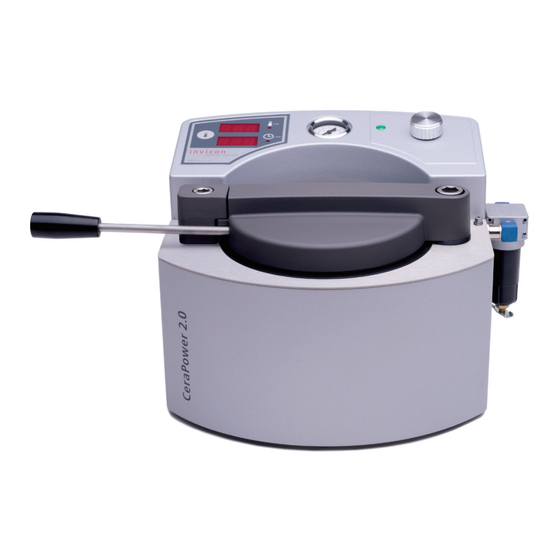
  • Seite 55 Max. Betriebstemperatur 120 °C Volumen 2 Liter Netzspannung 230 V/50 Hz 220 V/60 Hz 115 V/60 Hz (Spannung/Frequenz siehe Typenschild) Min. Kompressordruck 4 bar Max. Kompressordruck 10 bar 4 | invicon Gebrauchsinformation CeraPower 2.0 invicon Gebrauchsinformation CeraPower 2.0 | 55...
  • Seite 56 Hersteller freigegeben sind. Für und verstanden hat. Erst dann darf der Bediener das Schäden, die durch den Einsatz fremder Teile entstehen, Gerät in Betrieb nehmen. übernehmen wir keine Haftung. 56 | invicon Gebrauchsinformation CeraPower 2.0 invicon Gebrauchsinformation CeraPower 2.0...
  • Seite 57 Dafür den mitgelieferten Druckschlauch auf die Schlauchtülle (25) des Gerätes schieben und mittels einer Schlauchklemme fixieren. Am anderen Ende des Schlauches die Schnellkupplung montieren und mit der Druckleitung verbinden. invicon Gebrauchsinformation CeraPower 2.0 | 57 6 | invicon Gebrauchsinformation CeraPower 2.0...
  • Seite 58 Öffnen des Deckels nur zulässt, wenn der Betriebs- wenn die Temperatur des Glyzerinbades unter 95°C druck im Gerät abgebaut und die Temperatur unter abgefallen ist. 95°C (203°F) gesunken ist. Dieses gilt auch bei Strom- ausfall. 58 | invicon Gebrauchsinformation CeraPower 2.0 invicon Gebrauchsinformation CeraPower 2.0...
  • Seite 59 248°F angezeigt. Zur Bestätigung der gewählten Temperaturbezeichnung Einstellknopf (b) 1 x drücken. Im Display Zeit und Temperatur (d + f) erscheinen 0. Weiter wie ab Punkt 2.5 beschrieben. invicon Gebrauchsinformation CeraPower 2.0 | 59 8 | invicon Gebrauchsinformation CeraPower 2.0...
  • Seite 60 Risiko von Sachschäden ode Vorsicht! - Risiko von Sachschäden den für die Umwelt - Risiko von Schäden für die Umwelt Symbol für einen nützlichen Hinweis und Informationen Symbol für eine erforderliche Aktivität > 60 | invicon Gebrauchsinformation CeraPower 2.0 invicon Gebrauchsinformation CeraPower 2.0...
  • Seite 61 Beanspruchung, ungeeigneter Betriebsmittel und sol- cher chemischer, elektrochemischer oder elektrischer Einflüsse entstehen, die nach dem Vertrag nicht vor- ausgesetzt sind. Durch seitens des Bestellers oder Drit- ter unsachgemäß vorgenommene Änderungen oder invicon Gebrauchsinformation CeraPower 2.0 | 61 10 | invicon Gebrauchsinformation CeraPower 2.0...
  • Seite 62 Temperatur im Druckbehälter zu hoch Gerät muss weiter abkühlen ◾ ◾ Klixon Type: 1822 L 20-4 98°C Temperaturwächter austauschen (Temperaturwächter) defekt ◾ ◾ Magnetventil defekt Magnetventil muss vom Fachmann ausgetauscht werden 62 | invicon Gebrauchsinformation CeraPower 2.0 invicon Gebrauchsinformation | 11 CeraPower 2.0...
  • Seite 63 Bodenplatte PM 1-3 510964 Hauptschalter 50848 Netzanschluß/Sicherungshalter 51208 Überdruckventil 50792 Manometer 50702 Drehwertgeber 55200P Deckel Anschlag 50305 Distanzscheibe Deckelbolzen 51331 Geräterückwand PM 1, 1/120°C 510977 Magnetventil 50741-2 Ablasshahn 50744 invicon Gebrauchsinformation CeraPower 2.0 | 63 12 | invicon Gebrauchsinformation CeraPower 2.0...
  • Seite 64 2004 Displayfolie klebbar PM 1+3 510209 Gleichrichter Magnetventil 50741B-Brücke Handgriff D-50319 12/22 Magnetventil 50741 O-Ring 164 x 4/120°C 51168 Temperaturwächter Deckel 50701 Temperaturwächter Haltetemperatur 50935 Signalleuchte grün 50843 64 | invicon Gebrauchsinformation CeraPower 2.0 invicon Gebrauchsinformation | 13 CeraPower 2.0...
  • Seite 65 EXPLOSIONSZEICHNUNG invicon Gebrauchsinformation CeraPower 2.0 | 65 14 | invicon Gebrauchsinformation CeraPower 2.0...
  • Seite 66 WIRKSCHALTPLAN 66 | invicon Gebrauchsinformation CeraPower 2.0 invicon Gebrauchsinformation | 15 CeraPower 2.0...
  • Seite 67 PNEUMATIKPLAN invicon Gebrauchsinformation CeraPower 2.0 | 67 16 | invicon Gebrauchsinformation CeraPower 2.0...
  • Seite 68 EN 61010-2-010:2003: Sicherheitsbestimmungen für elektrische Mess-, Steuer-, Regel- und Laborgeräte - Teil2-010: Allgemeine Anforderungen an Laborgeräte für das Erhitzen von Stoffen (IEC 61010-2-010:2003) Deut- sche Fassung EN 61010-2-010:2003 68 | invicon Gebrauchsinformation CeraPower 2.0 invicon Gebrauchsinformation | 17 CeraPower 2.0...
  • Seite 69 Note...
  • Seite 70 Note...
  • Seite 72 Invicon chemical solutions GmbH Schweizer Straße 96 A 6830 Rankweil Austria Tel.: +43 (5522) 45301 – 0 Fax: +43 (5522) 45301 – 10 office@invicon.at www.invicon.at...