Herunterladen Diese Seite drucken

Werbung

Verfügbare Sprachen

Verfügbare Sprachen

deutsch
EDR
Helios Ventilatoren
Elektronischer Druck Regler
Nr. 82938. 001/0113
Montage- und Betriebsvorschrift
L-BAL-E192-D 1320
Art.-Nr.

Werbung

loading

Inhaltszusammenfassung für Helios EDR

  • Seite 1 Helios Ventilatoren Elektronischer Druck Regler Nr. 82938. 001/0113 Montage- und Betriebsvorschrift L-BAL-E192-D 1320 Art.-Nr.
  • Seite 2 Montage- und Betriebsvorschrift EDR Inhaltsübersicht 1 Allgemeine Hinweise ........
  • Seite 3 Montage- und Betriebsvorschrift EDR 8.2 Messbereiche und Genauigkeit des Drucksensors . . . 9 Programmierung ........
  • Seite 4 Montage- und Betriebsvorschrift EDR Allgemeine Hinweise 1 Allgemeine Hinweise 1.1 Bedeutung der Betriebsanleitung Lesen Sie vor Installation und Inbetriebnahme sorgfältig diese Be- triebsanleitung, um einen korrekten Gebrauch sicherzustellen! Wir weisen darauf hin, dass diese Betriebsanleitung nur geräte- bezogen und keinesfalls für die komplette Anlage gilt! Die vorliegende Betriebsanleitung dient zum sicherheitsgerechten Arbeiten an und mit dem genannten Gerät.
  • Seite 5 Montage- und Betriebsvorschrift EDR Sicherheitshinweise tigt, übersetzt oder auf Datenträgern erfasst werden. Zuwider- handlungen sind schadensersatzpflichtig. Alle Rechte vorbehal- ten, einschließlich solcher, die durch Patenterteilung oder Eintra- gung eines Gebrauchsmusters entstehen. 2 Sicherheitshinweise Montage, elektrischer Anschluss und Inbetriebnahme dürfen •...
  • Seite 6 Montage- und Betriebsvorschrift EDR Produktübersicht Bei einer Störung oder bei Ausfall des Gerätes ist zur Ver- • meidung von Personen- oder Sachschäden eine separate Funktionsüberwachung mit Alarmierungsfunktionen erforder- lich, Ersatzbetrieb muss berücksichtigt werden! 3 Produktübersicht 3.1 Einsatzbereich Druckregelung für Lüftungssysteme.
  • Seite 7 Montage- und Betriebsvorschrift EDR Montage 3.3 Lagerung Das Gerät muss trocken und wettergeschützt in Originalver- • packung gelagert werden. Vermeiden Sie extreme Hitze- oder Kälteeinwirkung. • Vermeiden Sie zu lange Lagerzeiten (wir empfehlen max. ein • Jahr). 3.4 Entsorgung / Recycling Die Entsorgung muss sachgerecht und umweltschonend, nach den gesetzlichen Bestimmungen erfolgen.
  • Seite 8 Montage- und Betriebsvorschrift EDR Elektrische Installation Montieren Sie das Gerät außerhalb des Verkehrsbereiches, • achten Sie dabei jedoch auf gute Zugänglichkeit! Nicht benötigte Kabeleinführungen verschließen! • Schützen Sie das Gerät vor direkter Sonnenbestrahlung! • Der Drucksensor ist lageabhängig, deshalb muss die Monta- •...
  • Seite 9 Montage- und Betriebsvorschrift EDR Elektrische Installation Elektrische Einrichtungen niemals mit Wasser oder anderen • Flüssigkeiten reinigen. Information Die jeweiligen Anschlüsse sind im Anhang dieser Betriebsanlei- tung dargestellt ( Anschlussplan)! 5.2 EMV-gerechte Installation der Steuerleitungen Um Einstreuungen zu vermeiden, muss auf ausreichenden Ab- stand zwischen Netz- und Steuerleitungen geachtet werden.
  • Seite 10 
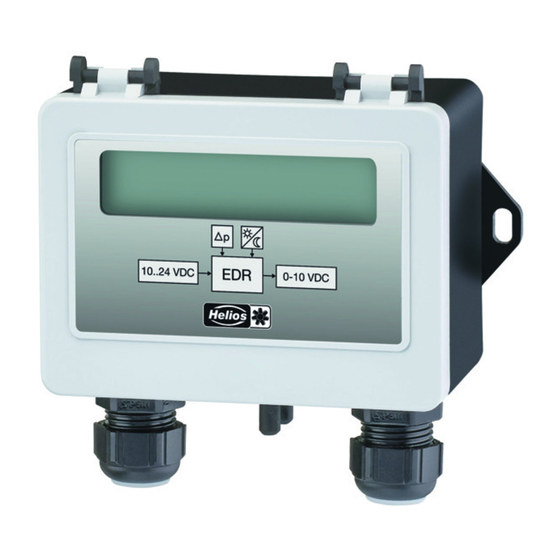
Montage- und Betriebsvorschrift EDR Geräteaufbau Der aktive Sollwert wird im Menü INFO angezeigt, ein aktiver “Sollwert 2” wird durch ein Mondsymbol signalisiert. 6 Geräteaufbau Für den elektrischen Anschluss und für die Programmierung muss der Klappdeckel aufgeschraubt werden. Anschließend wieder sorgfältig verschließen! LC-Display Mondsymbol = Einstellung für Soll-...
  • Seite 11 Montage- und Betriebsvorschrift EDR Menüführung 7 Menüführung 7.1 Menüstruktur Anzeige im Display nach Einschalten der 100 Pa INFO Δp Versorgungsspannung. Umschaltung zwischen Istwertanzeige und “INFO” mit der Tastenkombination für Escape (ESC = ▼ + ▲). 4.01 Beispiel für Betriebsart (Werkseinstellung) ▼...
  • Seite 12 Montage- und Betriebsvorschrift EDR Menüführung Änderung zu verlassen kann man die “ESC” Tastenkombination wählen, d. h. der ursprünglich eingestellte Wert bleibt erhalten. 4.01 4.00 “BASE SETUP” Umprogrammierung der Betriebsart 4.01 4.00 «4.01» «4.00» ▲ Mode Mode Mode Mode 7.2 Menüs der Betriebsarten 4.00...
  • Seite 13 Montage- und Betriebsvorschrift EDR Inbetriebnahme User Set- Parameter Werkseinstellung Funktion ting Offset Sensorabgleich 0 Pa 0 Pa - Parameter bei gewählter Betriebsart nicht vorhanden 8 Inbetriebnahme 8.1 Vorgehensweise 1. Das Gerät muss entsprechend der Betriebsanleitung montiert und angeschlossen sein. 2. Alle Anschlüsse sind nochmals auf Richtigkeit zu prüfen.
  • Seite 14 Montage- und Betriebsvorschrift EDR Programmierung Messbereiche und Genauigkeitsangaben ( 4.00 Ausgang 0 - 10 V) MB [Pa] +/-0,5 +/-0,5 +/-0,25 MB1: 0...1000 +/-0,7 +/-0,7 +/-0,5 MB2: 0...500 +/-0,9 +/-0,9 +/-0,9 MB3: 0...300 +/-1,0 +/-1,0 +/-1,25 MB4: 0...200 Temperaturdrift (bezogen auf die jeweils höchste Messspanne) Nullpunkt: +/-...
  • Seite 15 Montage- und Betriebsvorschrift EDR Programmierung 9.2 Drucksensor / Druckregler 4.00 4.01 9.2.1 Grundeinstellung 4.00 4.01 BASE SETUP BASE SETUP Mode 4.01 Mode Einstellung der Betriebsart z. B. 4.01 Measuring Range 0...1000 Pa Einstellung des gewünschten Druck-Messbereiches Measuring Range Einstellbereich: 0 - 200 Pa, 0 - 300 Pa, 0 - 500 Pa, 0 - 1000 Pa Werkseinstellung: max.
  • Seite 16 Montage- und Betriebsvorschrift EDR Sensorfunktion prüfen Max. Uout 10.0 V Max. Uout Einstellbereich maximale Ausgangsspannung (Drehzahlbe- grenzung): 10.0 V...0.0 V Werkseinstellung: 10.0 V 10 Sensorfunktion prüfen 1. Betriebsart für Drucksensor programmieren. 4.00 2. Spannungsversorgung (+Ub und GND) anlegen, Ausgang 0 - 10 V (A - GND) abklemmen.
  • Seite 17 Montage- und Betriebsvorschrift EDR Anhang 10 V DC 13...24 V DC Max. Belastung Ausgang 0 - 10 V 0,3 mA 10 mA (kurzschlussfest) Max. Stromaufnahme ca. 6 mA 14 mA Druckanschlüsse "+, -": Schlauchtüllen d = 5 / 6 mm Gehäuse...
  • Seite 18 Montage- und Betriebsvorschrift EDR Anhang 11.2 Anschlussplan Ri=4k Versorgung 10 ..24 VDC 10 V: Imax 6 mA 13-24 V: Imax 14 mA Setpoint 1/2 10 ..24 VDC Imax 6 mA Analog- Ausgang Steuerleitungen 0-10V max. 30m, ab 20m +UB/GND 10 V / 0,3 mA...
  • Seite 19 Montage- und Betriebsvorschrift EDR Anhang 11.3 Maßblatt [mm] ø6 ø5 KT00042A 16.06.2011 L-BAL-E192-D 1320 Art.-Nr. 19/20...
  • Seite 20 Montage- und Betriebsvorschrift EDR Anhang 11.4 Service und Information HELIOS Ventilatoren GmbH & Co • Lupfenstraße 8 • 78056 VS-Schwenningen HELIOS Ventilateurs • Le Carré des Aviateurs • 157 av. Charles Floquet • 93150 Le Blanc Mesnil Cedex HELIOS Ventilatoren AG •...
  • Seite 21 Helios fans Electronic pressure controller no. 82938. 001/0113 Installation and Operating Specication L-BAL-E192-GB 1320 Part.-No.
  • Seite 22 Installation and Operating Specification EDR Content General notes ..........
  • Seite 23 Installation and Operating Specification EDR 9.2.1 Basic setting ..... . 4.00 4.01 9.2.2 Settings for operation modes only ....
  • Seite 24 Installation and Operating Specification EDR General notes 1 General notes 1.1 Structure of the operating instructions Before installation and start-up, read this manual carefully to ensure correct use! We emphasize that these operating instructions apply to specific units only, and are in no way valid for the complete system! Use these operating instructions to work safely with and on the device.
  • Seite 25 Installation and Operating Specification EDR Product overview The equipment is to be used solely for the purposes specified and confirmed in • the order. Other uses which do not coincide with, or which exceed those specified will be deemed unauthorised unless contractually agreed. Damages resulting from such unauthorised uses will not be the liability of the manufacturer.
  • Seite 26 Installation and Operating Specification EDR Mounting 3.3 Storage The device must be stored in its original packaging in a dry and weather-proof • room. Avoid exposure to extreme heat and cold. • Avoid over-long storage periods (we recommend a maximum of one year).
  • Seite 27 Installation and Operating Specification EDR Electrical installation 5 Electrical installation 5.1 Safety precautions Danger due to electric current Work on electric components may only be carried out by trained electricians or by • persons instructed in electricity under the supervision of an electrician in accord- ance with electrical engineering regulations.
  • Seite 28 Installation and Operating Specification EDR Device construction The active Setpoint is indicated in the menu INFO, an active “Setpoint 2” is signalized by the moon symbol. 6 Device construction Screw off the hinged cover to proceed with electrical connection and programming.
  • Seite 29 Installation and Operating Specification EDR Menu operation 7 Menu operation 7.1 Menu structure Display after turning on the voltage supply. 100 Pa Switch over between actual value display and “INFO” with INFO Δp the key shortcut for Escape (ESC = ▼ + ▲).
  • Seite 30 Installation and Operating Specification EDR Menu operation 7.2 Menus of Modes 4.00 4.01 Parameter Factory setting User Setting Function INFO Display actual value for differential pres- 0 Pa 0 Pa Δp sure Setpoint 1 500 Pa Display active Setpoint Uout 0.0 V...
  • Seite 31 Installation and Operating Specification EDR Start-up 8 Start-up 8.1 Procedure 1. You must mount and connect the device in accordance with the operating instruc- tions. 2. Double check that all connections are correct. 3. The supply voltage must match the information on the rating plate.
  • Seite 32 Installation and Operating Specification EDR Programming 9 Programming 9.1 Select operation mode Information Simple installation is possible through the selection of the preprogrammed mode of operation. This determines the basic function of the device, factory set 4.01 Mode Function Pressure sensor output 0...10 V proportional to measuring range 4.00...
  • Seite 33 Installation and Operating Specification EDR Check sensor function 4.01 9.2.2 Settings for operation modes only SETTING SETTING Setpoint 1 500 Pa Setting range: Setpoint 1: 0...100 % sensor measuring range Setpoint 1 Factory setting: 50 % sensor measuring range Setpoint 2 500 Pa Setting “Setpoint 2”...
  • Seite 34 Installation and Operating Specification EDR Enclosure 11 Enclosure 11.1 Technical data Type Part-No. 01437 Pressure measuring range 1 0...1000 Pa Pressure measuring range 2 0...500 Pa Pressure measuring range 3 0...300 Pa Pressure measuring range 4 0...200 Pa Voltage supply 10 V...24 V DC...
  • Seite 35 Installation and Operating Specification EDR Enclosure 11.2 Connection diagram Ri=4k Versorgung 10 ..24 VDC 10 V: Imax 6 mA 13-24 V: Imax 14 mA Setpoint 1/2 10 ..24 VDC Imax 6 mA Analog- Ausgang Steuerleitungen 0-10V max. 30m, ab 20m...
  • Seite 36 Installation and Operating Specification EDR Enclosure 11.3 Dimensions [mm] ø6 ø5 KT00042A 16.06.2011 L-BAL-E192-GB 1320 Part.-No. 16/17...
  • Seite 37 Installation and Operating Specification EDR Enclosure 11.4 Service and Information HELIOS Ventilatoren GmbH & Co • Lupfenstraße 8 • 78056 VS-Schwenningen HELIOS Ventilateurs • Le Carré des Aviateurs • 157 av. Charles Floquet • 93150 Le Blanc Mesnil Cedex HELIOS Ventilatoren AG •...
  • Seite 38 Ventilateurs Helios Régulateur de pression électronique N° 82938. 001/0113 Prescription de montage et d’utilisation L-BAL-E192-F 1320 Art.N°.
  • Seite 39 Prescription de montage et d’utilisation EDR Sommaire Instructions générales ........
  • Seite 40 Prescription de montage et d’utilisation EDR 9.2.1 Réglage de base ....4.00 4.01 9.2.2 Réglages pour le fonctionnement, uniquement ..
  • Seite 41 Prescription de montage et d’utilisation EDR 1 Instructions générales 1.1 Importance de la notice d’utilisation Avant l’installation et la mise en service, veuillez lire cette notice d’utilisation attentive- ment afin de garantir une utilisation correcte ! Nous attirons votre attention sur le fait que cette notice d’utilisation ne concerne que l'appareil et n'est absolument pas applicable à...
  • Seite 42 Prescription de montage et d’utilisation EDR accidents et des prescriptions nationales ainsi que locales correspondantes et être en possession des instructions internes à l’entreprise. L'appareil ne peut être utilisé que pour la fonction pour laquelle il à été conçu, et •...
  • Seite 43 Prescription de montage et d’utilisation EDR 3.3 Stockage L'appareil doit être stocké au sec et à l’abri des intempéries dans son emballage • d’origine. Evitez des températures extrêmes vers le haut ou vers le bas. • Evitez de l’entreposer trop longtemps (nous recommandons un an au maximum).
  • Seite 44 Prescription de montage et d’utilisation EDR 5 Installation électrique 5.1 Mesures de sécurité Danger présenté par l'électricité Les travaux sur les pièces électriques doivent être effectués uniquement par un • électricien ou des personnes ayant reçu une formation dans ce domaine sous la surveillance d’un électricien conformément aux règles de la technique.
  • Seite 45 Prescription de montage et d’utilisation EDR 5.5 Entrée pour commutation Consigne 1 / Consigne 2 Par le biais d'une tension aux bornes “1” et “2” (10... 24 V DC) il est possible de commuter entre la valeur consigne 1 et la valeur consigne 2 (faire attention à la polarité...
  • Seite 46 Prescription de montage et d’utilisation EDR Ecran LC multifonctions et clavier interne Lignes de texte 1 avec 16 caractères pour afficher les valeurs actuelles et de 100 Pa consigne Δp Lignes de texte 2 avec 16 caractères pour afficher le texte du menu ▼...
  • Seite 47 Prescription de montage et d’utilisation EDR Sélection du groupe de menus (par ex. BASE SETUP) avec les touches fléchées vers la droite avec la touche ▼ vers la gauche avec la touche ▲. L’accès aux points de menu des groupes de menus (par ex. mode) est obtenu avec la touche P.
  • Seite 48 Prescription de montage et d’utilisation EDR Paramètres Réglages d'usine User Setting Fonction BASE SETUP Mode Réglage pour le mode de fonctionne- 4.00 4.01 ment Measuring Range Réglage en usine = plage maxi 1: 0...1000 Pa 2: 0...500 Pa 3: 0...300 Pa 4: 0...200 Pa...
  • Seite 49 Prescription de montage et d’utilisation EDR 8.2 Plages de mesure et précision du capteur de pression Les appareils sont réglés en usine sur la plage de mesure maximale (= MB1). Sélection- ner une plage de mesure la plus petite possible afin d'obtenir une précision maximale du capteur pour une résolution maximale du signal de sortie (...
  • Seite 50 Prescription de montage et d’utilisation EDR 9.2 Capteur de pression 4.00 / régulateur de pression 4.01 4.00 4.01 9.2.1 Réglage de base BASE SETUP BASE SETUP Mode 4.01 Réglage du mode de fonctionnement, par ex. 4.01 Mode Measuring Range 0...1000 Pa Réglage de la plage de mesure de pression souhaitée...
  • Seite 51 Prescription de montage et d’utilisation EDR 10 Contrôler le fonctionnement du capteur 1. Programmer le mode de fonctionnement pour le capteur de pression. 4.00 2. Appliquer la tension d'alimentation (+Ub et GND), déconnecter la sortie 0 - 10 V (A - GND).
  • Seite 52 Prescription de montage et d’utilisation EDR 11 Annexe 11.1 Caractéristiques techniques Type Réf. 01437 Plage de mesure de pression 1 0...1000 Pa Plage de mesure de pression 2 0...500 Pa Plage de mesure de pression 3 0...300 Pa Plage de mesure de pression 4 0...200 Pa...
  • Seite 53 Prescription de montage et d’utilisation EDR 11.2 Schémas des raccordements Ri=4k Versorgung 10 ..24 VDC 10 V: Imax 6 mA 13-24 V: Imax 14 mA Setpoint 1/2 10 ..24 VDC Imax 6 mA Analog- Ausgang Steuerleitungen 0-10V max. 30m, ab 20m...
  • Seite 54 Prescription de montage et d’utilisation EDR 11.3 Dimensions [mm] ø6 ø5 KT00042A 16.06.2011 L-BAL-E192-F 1320 Art.N°. 17/18...
  • Seite 55 Prescription de montage et d’utilisation EDR 11.4 Service et information HELIOS Ventilatoren GmbH & Co • Lupfenstraße 8 • 78056 VS-Schwenningen HELIOS Ventilateurs • Le Carré des Aviateurs • 157 av. Charles Floquet • 93150 Le Blanc Mesnil Cedex HELIOS Ventilatoren AG •...

Diese Anleitung auch für:

10831259