GEZE E 1500 S 24 V DC Anschlussplan
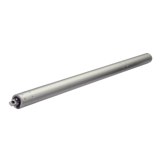
Spindelantrieb
Quicklinks
Achtung: Quetsch- und Klemmgefahr! Das Fenster schließt automatisch!
Vor Montage beiliegende Sicherheitshinweise lesen und bei Montage und Betrieb des Antriebs beachten! Gewährleistungsansprüche
setzen eine fachgerechte Montage, Installation und Wartung nach den Angaben des Herstellers voraus.
Attention: Danger of Crushing and Clamping! The Window Closes Automatically!
Before assembly read enclosed safety instruction and carry out during assembly and drive operation! Warranty claims presuppose profes-
sional assembly, installation and maintenance according to the guidelines of the manufacturer.
Zugehörige Montageanleitung ID 162882 beachten! / Observe associated installation instructions ID 162882!
X X
Anschlussplan ist gültig für Antriebe mit ID 162381 bis 162396. / Wiring diagram is valid for drives with ID 162381 to 162396.
X X
Zur Information des Elektrikers Schaltplan am Antrieb befestigen. / Attach circuit diagram to drive with adhesive tape for electrician.
X X
Der Antrieb ist vor Bauschmutz und Strahlwasser zu schützen. / Protect the drive from construction dirt and water spray.
X X
Technische Daten je Antrieb / Technical data per drive
Allgemeine Daten
Parameter
Zugkraft / Pull force [N]
Druckkraft / Push force [N]
Zuhaltekraft (befestigungsabhängig) / Holding force (dependent on the type of fixing) [N]
Hubgeschwindigkeit bei 2/3 Last / Stroke speed at 2/3 load [mm/s]
Hublänge / stroke length [mm]
Schubrohr / Slide tube
Gesamtlänge / Overall length [mm]
Umgebungstemperatur / ambient temperature [°C]
Schutzart / protection type
Schutzklasse / protection class
Anschlusskabel, Silikon, grau / Power supply cable, silicon, grey
Anwendungsbereich / Application area
Elektrische Daten - SELV / Electrical data - SELV
Parameter
Spannung / Voltage [V DC]
Max. Restwelligkeit U_ss [%] / max. ripple [%_Vss]
Einschaltdauer / Duty cycle [%]
Leistungsaufnahme / Input [W]
Stromaufnahme bei 2/3 Last / Power consumption at 2/3 load [A]
Abschaltstrom / Breaking current [A]
Endlagenabschaltung / end position cut-off
Technische Änderungen vorbehalten / Subject to technical change
Bei 24 V DC und langer Zuleitung muss das Kabel einen genügend großen Querschnitt haben, um einem Spannungsabfall
vorzubeugen. Querschnitt berechnen (siehe Kabelplan für RWA-Zentralen)!
Abzweigdosen müssen zugänglich sein. Flexible Leitungen nicht einputzen!
At 24 V DC and with long supply cable the cable must have a sufficiently large cross-section to prevent voltage drop.
Calculate cross-section (see cable plan for RWA control units)!
Junction boxes must be accessible. Do not recess flexible cables in wall!
E 1500 S 24 V DC
E 3000 24V DC
DE Spindelantrieb
EN Spindle drive
162884-00
E 1500 S 24V DC
Wert / Value
1500
1500
(bis Hub 1000 mm/ up to
stroke of 1000 mm)
25000
16
300-1000 (+/-5%)
Edelstahl / stainless steel
Hub / stroke +465
-5 / +75
IP 54
III
3 x 1.0 mm², 3 m
Trockene Räume / dry rooms
Wert / Value
24 V DC +/-25%
20
30 (ON: 3 Min. / OFF: 7 Min.)
72
3,0
4,0
Integrierte intelligente Lastabschaltelektronik /
Integrated intelligent electronic power cut-off unit
DE Anschlussplan
EN Wiring Diagram
E 3000 24V DC
3000
3000 (bis Hub 900 mm/ up to
stroke of 900 mm)
2400 (bis Hub 1000 mm/ up to
stroke of 1000 mm)
7,8
91
3,8
5,0

Verwandte Anleitungen für GEZE E 1500 S 24 V DC


Inhaltszusammenfassung für GEZE E 1500 S 24 V DC
- Seite 1 E 1500 S 24 V DC DE Anschlussplan EN Wiring Diagram E 3000 24V DC DE Spindelantrieb EN Spindle drive 162884-00 Achtung: Quetsch- und Klemmgefahr! Das Fenster schließt automatisch! Vor Montage beiliegende Sicherheitshinweise lesen und bei Montage und Betrieb des Antriebs beachten! Gewährleistungsansprüche setzen eine fachgerechte Montage, Installation und Wartung nach den Angaben des Herstellers voraus.
- Seite 2 WH cable is for communication when 2 drives are operated synchronously. Anschlussdose bauseitig / This requires pre-programmed synchro sets. on-site junction box Anschluss an GEZE-Notstromsteuerzentralen / Connection on GEZE Emergency power control unit 1. Motor / Letzter Motor / Zentralenauslegung / 24V DC 24V DC 1.