GEZE E740 Montageanleitung
Vorschau ausblenden
Andere Handbücher für E740:
- System- und montageanleitung (36 Seiten) ,
- Bedienungsanleitung (2 Seiten)

Verwandte Anleitungen für GEZE E740


Inhaltszusammenfassung für GEZE E740
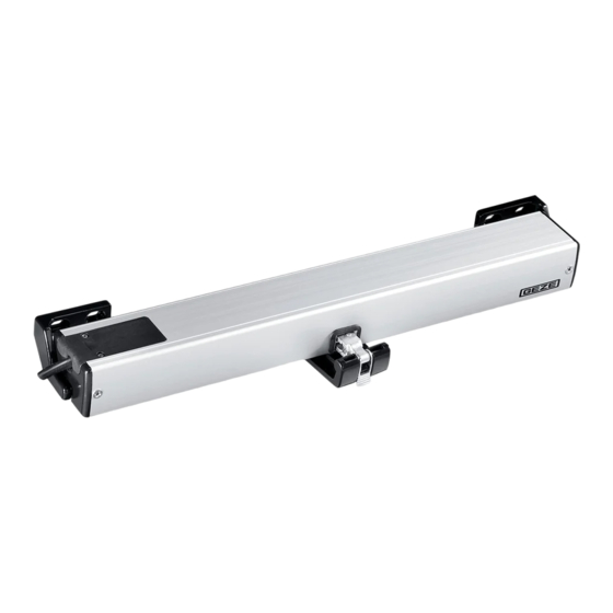
- Seite 1 Kettenantrieb E740 Chain Drive E740 24 V DC / 230 V AC Hub 100, 200, 300 oder 400 mm Stroke 100, 200, 300 or 400 mm System- und Montageanleitung Installation and Service Instructions Seite 2 Page 17 DE / GB - Mat. Nr. / Ident. no. 112408 - Zeichn. Nr. / Draw. no. 45140-9-0950 - Vers. 02...
-
Seite 2: Inhaltsverzeichnis
Montagemöglichkeiten allgemein Anwendungsbereich für Kippfenster einwärts und Klappfenster auswärts Anwendungsbereich für Dachfenster mit Antriebshalterung Dachfenster Verpackungsinhalt und BestelIbedarf Verpackungsinhalt Bestellbedarf Montageanleitung Montageanleitung Kippfenster einwärts Montageanleitung Klappfenster auswärts Montageanleitung Dachfenster Befestigungsmittel Elektrischer Anschluss E740 / 24V Elektrischer Anschluss E740 / 230V Herstellererklärung... -
Seite 3: Hinweise
Für die Sicherheit von Personen ist es wichtig, diesen Anweisungen Folge zu leisten. Diese Anweisungen sind aufzubewahren. Nur Sachkundige, die von GEZE autorisiert sind, dürfen Montage, Inbetriebnah- me und Wartung durchführen. Eigenmächtige Veränderungen an der Anlage schließen jede Haftung von GEZE für daraus resultierende Schäden aus. -
Seite 4: Montagehinweise
Montagehinweise ACHTUNG! WICHTIGE ANWEISUNG FÜR SICHERE MONTAGE! Alle Anweisungen beachten. Falsche Montage kann zu ernsthaften Verletzun- gen führen. Der Antrieb ist ausschließlich für den Einsatz in trockenen Räumen bestimmt. Nur die im Kabelplan angegebenen Kabel verwenden Für Litzenkabel grundsätzlich isolierte Aderendhülsen verwenden ... -
Seite 5: Wartung
Wartung GEZE schreibt mindestens einmal jährlich eine Wartung vor. Diese ist von einem Sachkundigen auszuführen. Dabei muss die Funktion, sowie der Zustand der Mecha- nik und der Stromleitung überprüft werden. Technische Daten Mechanische Daten E740 Schubkraft [N] Zugkraft [N] Schubgeschwindigkeit [mm/s]... -
Seite 6: Anwendungsbereich
Anwendungsbereich für Kippfenster einwärts und Klappfenster auswärts E740 als Solo montierbar, Flügelfläche max. 1,5 m² für vertikale und geneigte Fenster mit Einzelantrieb. Bei größeren Flügelflächen zusätzlich Verriegelungskonsole erforderlich, nur für Kippflügel erhältlich. max. Flügelgewicht: Berechnung siehe Diagramm Seite 7 Ü... - Seite 7 850 100, 200 und 300* ab 1300 100, 200, 300 und 400* * für Hub 300: Flügelhöhe 500-850 und Hub 400: Flügelhöhe 500-1300 E740 Schwenkkonsole einwärts ID-Nr. 122106 verwenden (separat zu bestellen) Klappfenster auswärts Einstellbarer Hub Flügelhöhe b [mm]...
-
Seite 8: Anwendungsbereich Für Dachfenster Mit Antriebshalterung Dachfenster
Anwendungsbereich für Dachfenster mit Antriebshalterung Dachfenster Flügelfläche max. 1,5 m² für Fenster mit Einzelantrieb max. Flügelgewicht: Berechnung siehe unten. Ü = Überschlag von 0 bis 20 mm Flügelhöhe Fh bis Drehbandmitte (Unterlage bauseits möglich) Platzbedarf auf dem Flügel a = Flügelbreite max. 1000 mm Platzbedarf für Antriebseinbau auf Rahmen min. -
Seite 9: Verpackungsinhalt Und Bestelibedarf
112341 weiß 9016 112342 nach RAL 112350 Kettenantrieb E740 EV 1 24 V DC 112351 weiß 9016 j Kettenantrieb E740 k Antriebshalterung rechts 112352 nach RAL l Antriebshalterung links o Abstandshalter (Montageanleitung und Schnellverschluss Bohrschablone in Verpackung) 112355 schwarz... -
Seite 10: Montageanleitung
Montageanleitung Montageanleitung Kippfenster einwärts 6.1.1 Bohrbild Befestigungslöcher für Antriebshalterungen (2), (3) und Kippkonsole (4) bohren, Bohrschablone (Farbe blau) verwenden. Platzbedarf 425 Mitte Fenster Flügelkante 6.1.2 Montage Antriebshalterungen (2) und (3) mit Hilfe von Abstandshalter (6) positionieren. Abstandshalter entfernen und Antriebshalterungen montieren. Kippkonsole (4) montieren. - Seite 11 Flügel öffnen, den Antrieb (1) auf die Antriebshalterungen (2, 3) montieren: Dazu die beiden Langlöcher am Ende des Antriebes (1) auf die zugehörigen Stifte der Antriebshalterungen (2, 3) einführen. Den Antrieb (1) um 90' drehen. einführen schwenken z.B.: Hub einstellen: Hubeinstellschalter drehend auf entsprechenden Hub einstellen: 1 = Hub 100 mm 2 = Hub 200 mm 3 = Hub 300 mm...
-
Seite 12: Montageanleitung Klappfenster Auswärts
Montageanleitung Klappfenster auswärts 6.2.1 Bohrbild Befestigungslöcher für Antriebshalterungen (2), (3) und Klappkonsole (5) bohren, Bohrschablone (Farbe rot) verwenden. Mitte Fenster Flügelkante 6.2.2 Montage Antriebshalterungen (2) und (3) mit Hilfe von Abstandshalter (6) positionieren. Abstandshalter entfernen und Antriebshalterungen montieren. Klappkonsole (5) montieren. Lage der Klappkonsole (5) bis 350 mm Flügelhöhe Lage der Klappkonsole (5) - Seite 13 Den Antrieb (1) auf die Antriebshalterungen (2, 3) montieren: Dazu die beiden Langlöcher am Ende des Antriebes (1) auf die zugehörigen Stifte der Antriebshalterungen (2, 3) einführen. Den Antrieb (1) um 90' drehen. einführen drehen z. B.: Hub einstellen: Hubeinstellschalter drehend auf entsprechenden Hub einstel- len: 1 = Hub 100 mm, 2 = Hub 200 mm, 3= Hub 300 mm und 4 = Hub 400 mm.
-
Seite 14: Montageanleitung Dachfenster
Montageanleitung Dachfenster 6.3.1 Bohrbild Befestigungslöcher für Antriebshalterungen (9), (10) und Klappkonsole (5) bohren. Bohrschablone (Farbe grün) verwenden. Mitte Fenster Flügelkante Platzbedarf min. 450 Stift und Schnellverschluss (7) an den 6.3.2 Montage Antrieb (1) montieren. Klappkonsole (5) montieren Antriebshalterungen für Dachfenster (8, 9) am Antrieb (1) einschieben und positionieren. -
Seite 15: Befestigungsmittel
Das Kettenendstück mit Stift und Schnellverschluss (7) in das Langloch der Klappkonsole (5) einführen. Bei Bedarf Kette ausfahren. Den Schnellanschluss (7) an der Klappkonsole (5) einrasten lassen. einführen einrasten z. B.: Hub einstellen: HubeinstelIschalter drehend auf entsprechenden Hub einstellen. 1 = Hub 100 mm 2 = Hub 200 mm 3 = Hub 300 mm 4 = Hub 400 mm... -
Seite 16: Elektrischer Anschluss E740 / 24V
Elektrischer Anschluss E740 / 24V Allgemeiner Anschluss Bei 24 V DC und langer Zuleitung muss das Kabel einen Ader "3" isolieren genügend großen Querschnitt aufweisen, um einem Spannungsabfall vorzubeugen. Querschnitt berechnen! 2-pol. Umschalter (siehe Kabelplan für RWA-Zentralen) Anschluss an Notstromsteuerzentralen E260N: Ader "3"... - Seite 36 GEZE Finland Free Trade Zone of Tianjin Port GmbH Industrieterrein, Kapelbeemd Tianjin, P.R. China Planken 1 Branch office of GEZE Scandinavia AB Leemkuil 1 Tel. +86 (0)22 26 97 39 95-0 Postbox 20 97944 Boxberg-Schweigern 5626 EA Eindhoven Fax +86 (0)22 26 97 27 02 158 71 Hollola Tel.