Herunterladen Diese Seite drucken

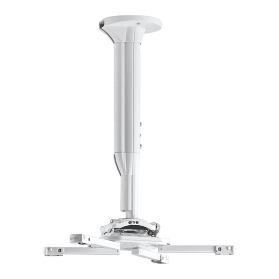
CHIEF KITEC Serie Montageanleitung

Projektorhalterungssets

Werbung

Verfügbare Sprachen

Verfügbare Sprachen

I N S T A L L A T I O N I N S T R U C T I O N S
I N S T R U C T I O N S D ' I N S T A L L A T I O N
M O N T A G E A N L E I T U N G
KITMC SERIES
KITEC SERIES
Projector Mount Kits
Kits de montage pour projecteurs
Projektorhalterungssets
KITEC/KITMC SERIES

Werbung

loading

Inhaltszusammenfassung für CHIEF KITEC Serie

  • Seite 1 I N S T A L L A T I O N I N S T R U C T I O N S I N S T R U C T I O N S D ' I N S T A L L A T I O N M O N T A G E A N L E I T U N G KITMC SERIES KITEC SERIES...
  • Seite 2 Do not use this product outdoors. no responsibility for accuracy, completeness or sufficiency of the information contained in this document. --SAVE THESE INSTRUCTIONS-- Chief® is a registered trademark of Milestone AV Technologies. All rights reserved. IMPORTANT SAFETY INSTRUCTIONS WARNING: A WARNING alerts you to the possibility of serious injury or death if you do not follow the instructions.
  • Seite 3 Installation Instructions KITEC/KITMC SERIES DIMENSIONS 2.95 KITEC 75.0 4.18 106.1 2.95 75.0 0.41 10.3 CABLE MANAGEMENT COVER HEIGHT ADJUSTABLE COLUMN HEIGHT ADJUSTMENT POINTS CABLE NOTES: MANAGEMENT 1. KITECXXXXXX COLUMNS ARE AVAILABLE IN A VARIETY COVER OF ADJUSTABLE LENGTHS. 2. THE PART NUMBER WILL DESIGNATE THE ADJUSTING COLUMN LENGTH RANGE.
  • Seite 4 KITEC/KITMC SERIES Installation Instructions LEGEND Tighten Fastener Pencil Mark Apretar elemento de fijación Marcar con lápiz Befestigungsteil festziehen Stiftmarkierung Apertar fixador Marcar com lápis Serrare il fissaggio Segno a matita Bevestiging vastdraaien Potloodmerkteken Serrez les fixations Marquage au crayon Loosen Fastener Drill Hole Aflojar elemento de fijación Perforar...
  • Seite 5 Installation Instructions KITEC/KITMC SERIES TOOLS REQUIRED FOR INSTALLATION 5/32” (included) M6 (included) (security) 1/2” 7/32” - wood studs 3/8" - concrete (U10) 5/16" - concrete (AF8) PARTS Hardware bag D (2) M6 x 6mm A (1) F (1) B (1) [Ceiling plate cover] [Shield ring] G (1)
  • Seite 6 KITEC/KITMC SERIES Installation Instructions Assembly And Installation Use two M6 x 16mm security screws (H) and washers removed in Step 2 to secure KITEC/KITMC Series mount column to adapter plate. (See Figure 3) Security Screw Installation (Optional) IMPORTANT ! : Washers must be reinstalled in the NOTE: Replacing standard button head cap screws with same order with the lock washers being closest to the...
  • Seite 7 Installation Instructions KITEC/KITMC SERIES Installing to a Wood Framework (Joists) Install two 5/16” x 2-3/4” (minimum) lag screws (not included) through holes on ceiling plate (A) and into holes IMPORTANT ! : KITEC/KITMC Series mounts are designed drilled in wood stud cross bracing. (See Figure 6) to be mounted to double 2"...
  • Seite 8 KITEC/KITMC SERIES Installation Instructions Installing to a Solid Concrete Ceiling Structure WARNING: KITEC/KITMC Series mounts are designed to be mounted to a concrete ceiling with a minimum thickness of 8" and a maximum drywall covering of 5/8” (1.6cm). WARNING: Fischer UX10 or AF8 anchors (not included) must be installed into structurally sound solid concrete.
  • Seite 9 Installation Instructions KITEC/KITMC SERIES Attach ceiling plate and attached extension column to SLMU Installation ceiling following instructions for corresponding ceiling Remove Screw Adapters from SLMU Legs structure. Press locking buttons on SLMU leg (K) firmly and Maneuver shield ring (B) so that it wraps around extension simultaneously push clip cover toward enclosed sliding stud column.
  • Seite 10 KITEC/KITMC SERIES Installation Instructions (N, P, Q, R or S) (T) x 3 or 4 (K) x 3 or 4 (with N or P only) screw adapters with nuts Figure 14 Figure 16 Adjust height-adjustment nuts to desired level. (See Press locking buttons on SLMU leg (K) firmly and Figure 15) simultaneously push clip cover away from enclosed sliding...
  • Seite 11 Installation Instructions KITEC/KITMC SERIES Maneuver legs so that sliding stud mount brackets and Projector Installation screws are towards the middle of the projector. (See Figure 18) and (See Figure 19) Install Projector With Interface Bracket Position sliding stud mount brackets and screws so that SLMU main plate (J) can be evenly mounted to legs.
  • Seite 12 KITEC/KITMC SERIES Installation Instructions ADJUSTMENTS WARNING: IMPROPER INSTALLATION CAN LEAD TO YAW Adjustment PROJECTOR FALLING RESULTING IN SERIOUS Loosen YAW adjustment locking screw using a #2 Phillips PERSONAL INJURY OR DAMAGE TO EQUIPMENT. Make screwdriver. (See Figure 23) certain mounting slots in mount base slide under thumb screws and that screws are seated in the back of slots.
  • Seite 13 Installation Instructions KITEC/KITMC SERIES Roll Adjustment Loosen ROLL adjustment locking screw using a #2 Phillips screwdriver. (See Figure 25) Turn ROLL micro-adjustment screw right or left using a #2 Phillips screwdriver until image is properly aligned on target. (See Figure 25) Tighten ROLL adjustment locking screw using a #2 Phillips height adjustment screwdriver.
  • Seite 14 KITEC/KITMC SERIES Installation Instructions Cable Management NOTE: (KITEC Series shown) If installing more than three cables through cable covers, the transitional cover may not fit well over the cables at the transition point. Follow Step 1 to help avoid this problem. (Optional) Use a utility knife to cut a section of lower cable cover off to create a larger space for the cables to transition into the upper cable cover.
  • Seite 15 Installation Instructions KITEC/KITMC SERIES Installing Transitional Cover Maneuver transitional cover (C) so that it is able to wrap around lower part of extension column. (See Figure 29) Wrap transitional cover (C) around lower part of extension column. (See Figure 29) Press transitional cover (C) into the base of upper part of extension column until the transition cover clicks into position.
  • Seite 16 AVERTISSEMENT : N'utilisez ce système de montage que Chief® est une marque déposée de Milestone AV pour l'usage prévu conformément à ces directives. N'utilisez Technologies. Tous droits réservés. pas d'accessoires non recommandés par le fabricant.
  • Seite 17 Installation Instructions KITEC/KITMC SERIES DIMENSIONS KITEC 2.95 75.0 4.18 106.1 2.95 75.0 0.41 10.3 1.82 46.3 2.95 KITMC 75.0 4.18 2.95 106.1 75.0 0.41 10.3 2.79 70.8...
  • Seite 18 KITEC/KITMC SERIES Installation Instructions OUTILS NÉCESSAIRES À L'INSTALLATION 4,0 mm (5/32") (fourni) M6 (fourni) (sécurité) 5,5 mm (7/32") (Poteaux en bois) 9,5 mm (3/8") (béton) (U10) 4,0 mm (5/32") (béton) (AF8) 12,7 mm (1/2") PIÈCES D (2) F (1) A (1) M6 x 6 mm [Couvercle de la plaque B (1)
  • Seite 19 Installation Instructions KITEC/KITMC SERIES Assemblage et installation IMPORTANT ! : Les rondelles doivent être installées à nouveau dans le même ordre, les rondelles de sécurité Installation de la vis de sécurité (en option) étant plus proches des tête des vis. (Voir la Figure 3) NOTE: Le remplacement des vis à...
  • Seite 20 KITEC/KITMC SERIES Installation Instructions Pose sur un montant en bois (solives) Installez deux vis tire-fond de 8 mm x 7 mm (5/16” x 2-3/4”) (minimum) (non incluses) dans les trous sur la plaque pour IMPORTANT ! : De série KITEC/KITMC est conçu pour être plafond et dans les trous percées dans les contreventements transversaux des montants en bois.
  • Seite 21 Installation Instructions KITEC/KITMC SERIES Installation sur un plafond en béton solide Serrez les quatre boulons pour fixer la plaque au plafond. (Voir la Figure 9) AVERTISSEMENT : Ces supports de série KITEC/KITMC sont conçu pour être monté sur un plafond en béton d'une épaisseur minimale de 203 mm (8") et un revêtement de Rondelles x 2 cloison sèche d'épaisseur maximale de 1,6 cm (5/8").
  • Seite 22 KITEC/KITMC SERIES Installation Instructions Fixez la plaque pour plafond et la colonne d'extension qui y Installation SLMU est attachée au plafond en respectant les instructions Retrait des adaptateurs à vis des pieds d'installation de la plaque pour plafond. SLMU Placez l'anneau (B) de sorte qu'il s'enroule autour de la colonne d'extension.
  • Seite 23 Installation Instructions KITEC/KITMC SERIES Déterminez la taille de vis correcte à insérer dans le projecteur. Placez les pieds SLMU (K) sur les adaptateurs à vis et les Testez les vis Phillips (N, P, Q, R et S) fournies jusqu'à ce que écrous de réglage de la hauteur.
  • Seite 24 KITEC/KITMC SERIES Installation Instructions Manœuvrez les pieds pour que les pattes et les vis de Installez le projecteur avec la patte de fixation fixation des montants coulissants se trouvent vers le milieu d'interface du projecteur. (Voir la Figure 18) et (Voir la Figure 19) Positionnez les pattes et les vis de fixation des montants coulissants de manière à...
  • Seite 25 Installation Instructions KITEC/KITMC SERIES AVERTISSEMENT : UNE INSTALLATION INCORRECTE (Vue arrière) PEUT PROVOQUER LA CHUTE DU PROJECTEUR ET CAUSER DE GRAVES BLESSURES CORPORELLES OU ENDOMMAGER L'ÉQUIPEMENT. Assurez-vous que les fentes de montage dans la base du système de montage glissent sous les vis de serrage et que les vis se bloquent à...
  • Seite 26 KITEC/KITMC SERIES Installation Instructions Réglage de l’inclinaison Réglage de la hauteur Desserrez la vis de blocage du réglage de l'inclinaison à l'aide d'un tournevis Phillips 2. (Voir la Figure 24) AVERTISSEMENT : Le fait de ne pas fournir un soutien Tournez la vis de réglage micrométrique de l'inclinaison adéquat pour ce système de montage pendant le processus vers la droite ou la gauche à...
  • Seite 27 Installation Instructions KITEC/KITMC SERIES Rangement des câbles NOTE: Pour une installation de plus de trois câbles à travers le cache-câble, le revêtement transitoire peut ne pas être correctement adapté aux câbles au niveau du point de transition. Suivez l'étape 1 pour résoudre ce problème. (En option) Utilisez un couteau tout usage pour couper une section du cache-câble inférieur pour créer un plus grand espace afin de permettre aux câbles de passer dans le...
  • Seite 28 KITEC/KITMC SERIES Installation Instructions Installation du revêtement transitoire Placez le revêtement transitoire (C) afin qu'il soit en mesure de s'enrouler autour de la pièce inférieure de la colonne d'extension. (Voir la Figure 29) Enroulez le revêtement transitoire (C) autour de la partie inférieure de la colonne d'extension.
  • Seite 29 Service-Center. Angemessenheit der in diesem Dokument enthaltenen Informationen. WARNUNG: Verwenden Sie das Produkt nie im Freien. Chief® ist eine eingetragene Marke von Milestone AV --BEWAHREN SIE DIESE ANWEISUNGEN AUF-- Technologies. Alle Rechte vorbehalten. WICHTIGE SICHERHEITSHINWEISE WARNUNG: WARNUNG weist darauf hin, dass bei Nichtbefolgung der Anweisungen Verletzungs- oder Lebensgefahr besteht.
  • Seite 30 KITEC/KITMC SERIES Installation Instructions ABMESSUNGEN KITEC 2.95 75.0 4.18 106.1 2.95 75.0 0.41 10.3 1.82 46.3 2.95 KITMC 75.0 4.18 106.1 2.95 75.0 0.41 10.3 2.79 70.8...
  • Seite 31 Installation Instructions KITEC/KITMC SERIES FÜR DIE MONTAGE ERFORDERLICHES WERKZEUG 4,0 mm (5/32") (mitgeliefert) (Sicherheit) (mitgeliefert) 5,5 mm (7/32") (Holzstollen) 9,5 mm (3/8") (Beton) (U10) Nr. 2 12,7 mm (1/2") 4,0 mm (5/32") (Beton) (AF8) TEILE Materialtasche D (2) F (1) M6 x6 mm A (1) B (1)
  • Seite 32 KITEC/KITMC SERIES Installation Instructions Montage und Installation Verwenden Sie zwei M6 x 16-mm (5/8")- Sicherheitsschrauben (H) und die in Schritt 2 entfernten Unterlegscheiben, um die Säule der KITEC-KITMC Serien- Montage der Sicherheitsschraube (Optional) Halterung an der Adapterplatte zu fixieren. (siehe Abb. 3) HINWEIS: Das Ersetzen der Standard- WICHTIG!: Die Unterlegscheiben müssen in der...
  • Seite 33 Installation Instructions KITEC/KITMC SERIES Montage an einem Holzrahmen (Deckenträger) WICHTIG!: Der KITEC-KITMC-Serien-Halterung eignet sich für die Montage an einer doppelten Querverstrebung aus 5 cm x 10 cm (2" x 4")-Holzbalken (12,7 cm (5") im Zentrum) zwischen zwei Deckenbalken mit einer Gipskartonbeschichtung von maximal 1,6 cm (5/8").
  • Seite 34 KITEC/KITMC SERIES Installation Instructions Montage an einer abgehängten Decke Montage an einer Massivbetondecke HINWEIS: Die CPA-Halterung kann an vier Gewindestangen mit einem Durchmesser von 9,5 mm (3/8") (nicht mitgeliefert) aufgehängt werden, die mittels (nicht WARNUNG: Der KITEC-KITMC Serien-Halterung eignen mitgelieferter) 9,5 mm (3/8")-Kanalmuttern an einer sich zur Montage an einer Betondecke mit einer 3,2–16 mm x 3,2–16 mm (1-5/8"...
  • Seite 35 Installation Instructions KITEC/KITMC SERIES Befestigen Sie gemäß den Anweisungen zur Montage der Deckenplatte diese und die angefügte Ausziehsäule an der Decke. Unterlegscheiben Bewegen Sie den Ring (A) so, dass er die Ausziehsäule umschließt. (Siehe Abb. 11) Hüllen Sie den Ring (A) um die Ausziehsäule. (Siehe Abb.
  • Seite 36 KITEC/KITMC SERIES Installation Instructions SLMU Installation Führen Sie die Schrauben durch die Schraubadapter mit den Höheneinstellmuttern in die Projektorlöcher ein. (Siehe Entfernen der Schraubadapter von den Abb. 14) SLBU/SLMU-Beinen HINWEIS: Verwenden Sie die Unterlegscheiben (T) nur, Drücken Sie fest auf die Feststellknöpfe am SLMU-Bein (K) wenn Sie M- oder N-Schrauben zur Befestigung der und schieben Sie gleichzeitig die Clip-Abdeckung in Richtung Schraubadapter am Projektor benutzen.
  • Seite 37 Installation Instructions KITEC/KITMC SERIES Platzieren Sie die SLMU-Beine (B) über den Richten Sie die Beine so aus, dass die Schraubadaptern mit den Höheneinstellmuttern. Schiebebalkenhalterplatten mit den Schrauben zur Mitte (Siehe Abb. 16) des Projektors zeigen. (Siehe Abb. 18) und (Siehe Abb. 19) Positionieren Sie die Schiebebalkenhalterplatten mit den HINWEIS: Achten Sie darauf, dass die Armverschlussclips...
  • Seite 38 KITEC/KITMC SERIES Installation Instructions Montage eines Projektors mit Anschlussplatte Nur ein Beispiel (Anschlussplatte je nach Projektor- WARNUNG: EINE UNSACHGEMÄSSE MONTAGE modell verschieden) KANN ZUM HERUNTERFALLEN DES PROJEKTORS FÜHREN UND SCHWERE VERLETZUNGEN ODER GERÄTESCHÄDEN VERURSACHEN. Verwenden Sie KEINE Ersatz-Befestigungsmaterialien. Verwenden Sie nur die vom Hersteller mitgelieferten Befestigungsmaterialien.
  • Seite 39 Installation Instructions KITEC/KITMC SERIES EINSTELLUNGEN (KITEC Gezeigt) Einstellung der Drehung um die HÖHENACHSE Lösen Sie die Feststellschraube für die Einstellung der Drehung um die HÖHENACHSE mit einem Nr. 2- Kreuzschlitzschraubendreher. (Siehe Abb. 23) Drehen Sie die Mikro-Justierschraube zur Einstellung der Drehung um die HÖHENACHSE mit einem Nr.
  • Seite 40 KITEC/KITMC SERIES Installation Instructions Höheneinstellung Kabelführung HINWEIS: Falls Sie mehr als drei Kabel durch Kabelabdeckungen montieren, ist es möglich, dass WARNUNG: Wenn diese Halterung während der die Überleitungsabdeckung am Überleitungspunkt Höheneinstellung nicht ordnungsgemäß festgehalten wird, nicht problemlos über die Kabel passt. Befolgen kann dies zu schweren Verletzungen oder Geräteschäden Sie Schritt 1, um dieses Problem zu vermeiden.
  • Seite 41 Installation Instructions KITEC/KITMC SERIES Führen Sie die Kabel durch die untere Kabelabdeckung. Montage der Überleitungsabdeckung (Siehe Abb. 28) Bewegen Sie die Überleitungsabdeckung (C) so, dass sie Führen Sie die Kabel durch die obere Kabelabdeckung. den unteren Teil der Ausziehsäule umschließen kann. (Siehe Abb.
  • Seite 42 KITEC/KITMC SERIES Installation Instructions...
  • Seite 43 Installation Instructions KITEC/KITMC SERIES...
  • Seite 44 Europe A Franklinstraat 14, 6003 DK Weert, Netherlands P +31 (0) 495 580 852 F +31 (0) 495 580 845 Chief, a products division of Asia Pacific A Office No. 918 on 9/F, Shatin Galleria Milestone AV Technologies 18-24 Shan Mei Street...